Kramer TP-576 User manual

KRAMER ELECTRONICS LTD.
USER MANUAL
MODEL:
TP-576
HDMI/CAT 5 Line Driver
P/N: 2900-000760 Rev 4
im Vertrieb von
CAMBOARD Electronics
www.camboard.de
Tel. 07131 911201
Fax 07131 911203

im Vertrieb von
CAMBOARD Electronics
www.camboard.de
Tel. 07131 911201
Fax 07131 911203

TP-576 – Contents
i
Contents
1Introduction 1
2Getting Started 2
2.1 Achieving the Best Performance 2
2.2 Safety Instructions 3
2.3 Recycling Kramer Products 3
3Overview 4
3.1 Using Twisted Pair Cable 5
3.2 About the Power Connect™ Feature 5
3.3 Defining the TP-576 HDMI/CAT 5 Line Driver 6
4Connecting the TP-576 7
4.1 Connecting to the TP-576 via RS-232 10
4.2 Connecting an IR Emitter/Sensor 10
5Operating the TP-576 11
5.1 Controlling via RS-232 11
5.2 Controlling via Infrared 12
5.3 Wiring the TP LINE IN / LINE OUT RJ-45 Connectors 15
5.4 Acquiring the EDID 16
5.5 Disabling/Enabling Deep Color Support 17
6Default EDID 18
7Technical Specifications 19
8Default Communication Parameters 20
9Kramer Protocol 2000 21
Figures
Figure 1: TP-576 HDMI/CAT 5 Line Driver 6
Figure 2: Connecting the TP-576 HDMI/CAT 5 Line Driver 9
Figure 3: TP-576 RS-232 Signals 11
Figure 4: TP-576 IR Control –Example I 12
Figure 5: TP-576 IR Control –Example II 13
Figure 6: TP-576 IR Control –Example III 14
Figure 7: TP PINOUT 15
im Vertrieb von
CAMBOARD Electronics
www.camboard.de
Tel. 07131 911201
Fax 07131 911203

TP-576 - Introduction
1
1 Introduction
Welcome to Kramer Electronics! Since 1981, Kramer Electronics has been
providing a world of unique, creative, and affordable solutions to the vast range of
problems that confront video, audio, presentation, and broadcasting professionals
on a daily basis. In recent years, we have redesigned and upgraded most of our
line, making the best even better!
Our 1,000-plus different models now appear in 11 groups that are clearly defined
by function: GROUP 1: Distribution Amplifiers; GROUP 2: Switchers and Routers;
GROUP 3: Control Systems; GROUP 4: Format/Standards Converters; GROUP 5:
Range Extenders and Repeaters; GROUP 6: Specialty AV Products; GROUP 7:
Scan Converters and Scalers; GROUP 8: Cables and Connectors; GROUP 9:
Room Connectivity; GROUP 10: Accessories and Rack Adapters and GROUP 11:
Sierra Products.
Congratulations on purchasing your Kramer TP-576 HDMI/CAT 5 Line Driver,
which is ideal for the following typical applications:
Home theater, presentation and multimedia applications
Rental and staging
im Vertrieb von
CAMBOARD Electronics
www.camboard.de
Tel. 07131 911201
Fax 07131 911203

2
TP-576 - Getting Started
2 Getting Started
We recommend that you:
Unpack the equipment carefully and save the original box and packaging
materials for possible future shipment
Review the contents of this user manual
Go to http://www.kramerelectronics.com/support/product_downloads.asp
to check for up-to-date user manuals, application programs, and to check if
firmware upgrades are available (where appropriate).
2.1 Achieving the Best Performance
To achieve the best performance:
Use only good quality connection cables (we recommend Kramer high-
performance, high-resolution cables) to avoid interference, deterioration in
signal quality due to poor matching, and elevated noise levels (often
associated with low quality cables)
Do not secure the cables in tight bundles or roll the slack into tight coils
Avoid interference from neighboring electrical appliances that may adversely
influence signal quality
Position your Kramer TP-576 away from moisture, excessive sunlight and
dust
This equipment is to be used only inside a building. It may only be
connected to other equipment that is installed inside a building.
You must use shielded twisted pair (STP) cabling with the TP-576,
(refer to Section 3.1 for further details).
i
!
!
im Vertrieb von
CAMBOARD Electronics
www.camboard.de
Tel. 07131 911201
Fax 07131 911203

TP-576 - Getting Started
3
2.2 Safety Instructions
Caution:
There are no operator serviceable parts inside the unit
Warning:
Use only the Kramer Electronics input power wall
adapter that is provided with the unit
Warning:
Disconnect the power and unplug the unit from the wall
before installing
2.3 Recycling Kramer Products
The Waste Electrical and Electronic Equipment (WEEE) Directive 2002/96/EC
aims to reduce the amount of WEEE sent for disposal to landfill or incineration by
requiring it to be collected and recycled. To comply with the WEEE Directive,
Kramer Electronics has made arrangements with the European Advanced
Recycling Network (EARN) and will cover any costs of treatment, recycling and
recovery of waste Kramer Electronics branded equipment on arrival at the EARN
facility. For details of Kramer’s recycling arrangements in your particular country
go to our recycling pages at http://www.kramerelectronics.com/support/recycling/.
!
im Vertrieb von
CAMBOARD Electronics
www.camboard.de
Tel. 07131 911201
Fax 07131 911203

4
TP-576 - Overview
3 Overview
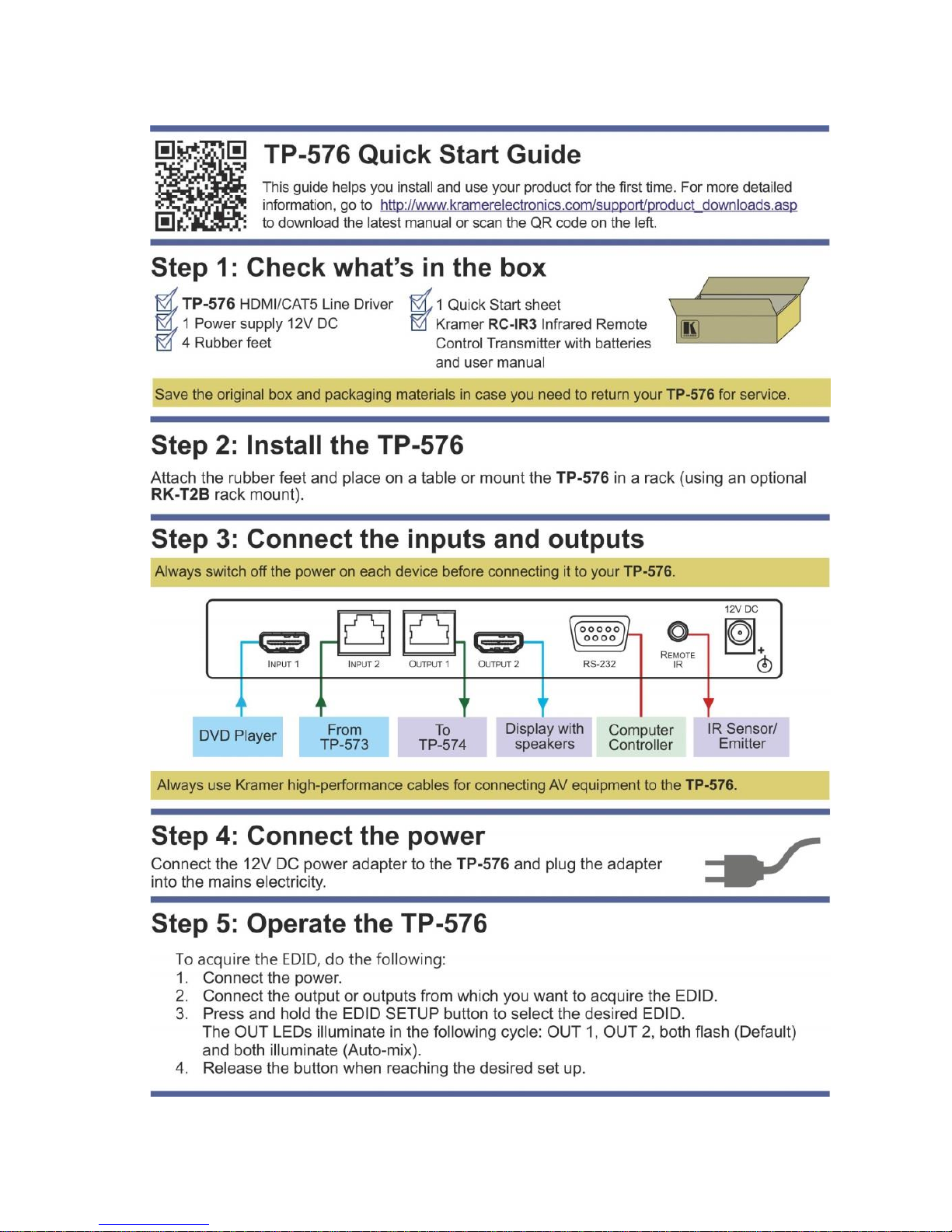
The TP-576 is a twisted pair line driver for HDMI, bidirectional RS-232 and infrared
signals. The TP-576 receives an HDMI signal either from a local HDMI source or
from a transmitter (for example, the Kramer TP-573) via the LINE IN RJ-45
connector. The TP-576 decodes these input signals to the local outputs and
simultaneously transmits them to a TP receiver (for example, the TP-574) which
converts them back to HDMI, RS-232 and infrared signals.
Using the TP-576, you can pass via the twisted pair cable:
EDID (Extended Display Information Data) and HDCP signals between the
TP-573 and TP-574
HPD (Hot Plug Detect) signals from the display device to the source
The TP-576 features:
6.75Gbps (2.25Gbps per graphic channel, HDMI); 4.95Gbps (1.65Gbps per
graphic channel, twisted pair inputs and outputs)
Suitable for resolutions up to UXGA at 60Hz, and for all HD resolutions.
An RS-232 baud rate of up to 38.4kbps
HDTV compatibility and HDCP compliance
Bidirectional RS-232 and IR interfaces. The IR input/output transmits and
receives IR commands over CAT 5 cable between the transmitter and
receiver
Compatible with a Kramer transmitter and via a Kramer external remote receiver:
C-A35M/IRR or C-A35M/IRE or C A35M/2IRE
A system range of up to 90m (295ft) at 1080i, or up to 30m (98ft) at 1080p on
shielded BC-DGKat524 cable; 90m (295ft) at 1080i, or up to 70m (230ft) at
1080p on shielded BC-DGKat623 cable; 100m (330ft) at 1080i or up to 90m
(295ft) at 1080p on shielded BC-DGKat7a23 cable
Note that the transmission range depends on the signal resolution, graphics card and
display used. The distance using non-Kramer CAT 5, CAT 6 and CAT 7a cables may
not reach these ranges
Use only shielded cables with the TP-576 in which the cable
Ground shielding must be connected/soldered to the shield of both
RJ-45 connectors
!
im Vertrieb von
CAMBOARD Electronics
www.camboard.de
Tel. 07131 911201
Fax 07131 911203

TP-576 - Overview
5
HDMI support for Deep Color (on the HDMI input), x.v.Color™, HDMI
Uncompressed Audio Channels, Dolby TrueHD, DTS-HD
3D pass-through
The Power Connect System™ where a single connection to the TP-576
powers the transmitter, receiver and line driver units
The ability to read and store, in non-volatile memory, the default EDID, or the
EDID block from either or both of the output display devices, so it can then
provide the EDID information to the HDMI sources even if the display device
is not connected
LEDs indicating the selected input and active output LED indicators
The TP-576 is 12V DC fed and is housed in a MegaTOOLS® enclosure where two
units can be rack mounted side-by-side in a 1U rack space with the optional
RK-T2B rack adapter.
3.1 Using Twisted Pair Cable
Kramer engineers have developed special twisted pair cables to best match our
digital twisted pair products; the Kramer: BC-DGKat524 (CAT 5 24 AWG), the
Kramer: BC-DGKat623 (CAT 6 23 AWG cable), and the Kramer: BC-DGKat7a23
(CAT 7a 23 AWG cable). These specially built cables significantly outperform
regular CAT 5/CAT 6/CAT 7a cables.
The TP-573 / TP-574 cannot work with unshielded cables.
3.2 About the Power Connect™ Feature
The Power Connect™ feature here means that the TP-576 unit can power both
the transmitter and receiver when they are within 270 feet (90 meters) from the
TP-576. The Power Connect™ feature applies as long as the cable can carry
power. The distance does not exceed 90 meters on standard CAT 5 cable, for
longer distances, heavy gauge cable should be used.
CAT 5 cable is still suitable for the video/audio transmission, but not for feedingthe power at
these distances.
!
im Vertrieb von
CAMBOARD Electronics
www.camboard.de
Tel. 07131 911201
Fax 07131 911203

6
TP-576 - Overview
3.3 Defining the TP-576 HDMI/CAT 5 Line Driver
This section defines the TP-576.
Figure 1: TP-576 HDMI/CAT 5 Line Driver
#
Feature
Function
1
IR Receiver
The yellow LED lights when receiving signals from the
infrared remote control transmitter
2
EDID SETUP Button
Press briefly to determine the type of EDID stored in the
non-volatile memory
Press and hold to select the desired EDID setup and then
release to acquire EDID (see Section 5.4)
3
INPUT SELECT Button
Press to select the input. The relevant IN LED illuminates
4
IN 1 LED
Illuminates when input 1 is selected
5
IN 2 LED
Illuminates when input 2 is selected
6
OUT 1 LED
Illuminates when output 1 is connected and active
Flashes when the monitor does not support HDCP
This LED also illuminates or flashes during EDID setup
(see Section 5.4)
7
OUT 2 LED
Illuminates when output 2 is connected and active
Flashes when the monitor does not support HDCP
8
ON LED
Illuminates when receiving power
9
INPUT 1 HDMI Connector
Connects to the HDMI source
10
INPUT 2 RJ-45 Connector
Connects to the CAT 5 IN RJ-45 connector on the TP-573
or TP-571
11
OUTPUT 1 RJ-45 Connector
Connects to the CAT 5 IN RJ-45 connector on the TP-574
or TP-572+
12
OUTPUT 2 HDMI Connector
Connects to the HDMI acceptor
13
RS-232 9-pin D-sub Connector
Connects to a PC or other controller
14
REMOTE IR 3.5mm Mini Jack
Connects to an infrared receiver/emitter
Compatible with a Kramer transmitter and via a Kramer
external remote IR receiver: C-A35M/IRR or
C-A35M/IRE or C A35M/2IRE
15
12V DC
+12V DC connector for powering the unit
im Vertrieb von
CAMBOARD Electronics
www.camboard.de
Tel. 07131 911201
Fax 07131 911203

TP-576 - Connecting the TP-576
7
4 Connecting the TP-576
Always switch off the power to each device before connecting it to your
TP-576. After connecting your TP-576, connect its power and then
switch on the power to each device.
To connect the TP-576 together with the TP-573 HDMI/RS-232/IR Line
Transmitter and the TP-574 HDMI/RS-232/IR Line Receiver, as illustrated in the
example in Figure 2, connect the following:
On the TP-573 connect:
1. An HDMI source (for example, a DVD player) to the HDMI IN connector.
2. An IR sensor or emitter to the IR 3.5mm mini jack connector (see
Section 4.2).
3. A PC to the RS-232 9-pin D-sub connector.
Alternatively, you can connect an RS-232 controllable device to the RS-232
port of the TP-573 and a PC to the RS-232 port of the TP-574.
4. A CAT 5 or CAT 6 cable to the LINE OUT RJ-45 twisted pair connector.
On the TP-576 connect:
1. An HDMI source (for example, a DVD player) to the HDMI INPUT 1
connector.
2. The CAT 5 or CAT 6 cable from the TP-573 to the INPUT 2 RJ-45 twisted
pair connector (to power the TP-576 as well as the TP-573 and TP-574).
3. An IR sensor or emitter to the REMOTE IR 3.5mm mini jack connector (see
Section 4.2).
4. The 12V DC power supply to the TP-576 (not shown in Figure 2) (to power
the TP-576 as well as the TP-573 and TP-574)
i
im Vertrieb von
CAMBOARD Electronics
www.camboard.de
Tel. 07131 911201
Fax 07131 911203

8
TP-576 - Connecting the TP-576
On the TP-574 connect:
1. The HDMI OUT connector to an HDMI acceptor (for example, an LCD
display with speakers).
2. An IR emitter or sensor to the IR 3.5mm mini jack connector (see
Section 4.2).
3. The RS-232 9-pin D-sub connector to an RS-232 acceptor (for example, an
RS-232 controllable device).
Alternatively, you can connect an RS-232 controllable device to the RS-232
port of the TP-573 and a PC to the RS-232 port of the TP-574.
4. The CAT 5 or CAT 6 cable from the TP-576 to the LINE IN RJ-45 twisted
pair connector.
5. The 12V DC power supply to the TP-576 (not shown in Figure 2).
im Vertrieb von
CAMBOARD Electronics
www.camboard.de
Tel. 07131 911201
Fax 07131 911203

TP-576 - Connecting the TP-576
9
Figure 2: Connecting the TP-576 HDMI/CAT 5 Line Driver
im Vertrieb von
CAMBOARD Electronics
www.camboard.de
Tel. 07131 911201
Fax 07131 911203

10
TP-576 - Connecting the TP-576
4.1 Connecting to the TP-576 via RS-232
You can connect to the TP-576 via an RS-232 connection using, for example, a
PC. Note that a null-modem adapter/connection is not required.
To connect to the TP-576 via RS-232, connect the RS-232 9-pin D-sub rear panel
port on the TP-576 unit via a 9-wire straight cable (only pin 2 to pin 2, pin 3 to pin 3,
and pin 5 to pin 5 need to be connected) to the RS-232 9-pin D-sub port on your PC.
4.2 Connecting an IR Emitter/Sensor
The TP-576 consists of an IR receiver and a REMOTE IR 3.5mm mini jack
connector that can connect to either an emitter or receiver.
In a transmitter-receiver configuration that includes, for example, the TP-573 and
TP-574, IR control behavior is determined by the IR items (emitter or receiver) that
are connected to the REMOTE IR or IR (for the TP-573 and TP-574) 3.5mm mini
jack connectors.
To control any device in this configuration, use the appropriate IR remote control
transmitter. For example, the Kramer remote controller will be able to control
Kramer devices. For controlling an LCD display you will need to use the LCD
remote controller unit, and so on.
im Vertrieb von
CAMBOARD Electronics
www.camboard.de
Tel. 07131 911201
Fax 07131 911203

TP-576 - Operating the TP-576
11
5 Operating the TP-576
This section explains how to:
Control the TP-576 via RS-232 or infrared signals
Wire the TP cable
Acquire the EDID
5.1 Controlling via RS-232
The TP-576 passes bidirectional RS-232 signals between the TP-573 and the
TP-574. For example, a PC connected to the RS-232 port on the TP-573 can
control an RS-232 controllable device on the TP-574.
You can connect a PC to the RS-232 port on the TP-576 via a straight connection
(see Section 5.1) to control the TP-576 only.
Figure 3: TP-576 RS-232 Signals
im Vertrieb von
CAMBOARD Electronics
www.camboard.de
Tel. 07131 911201
Fax 07131 911203

12
TP-576 - Operating the TP-576
5.2 Controlling via Infrared
Many IR control configurations are available; this section shows several
possibilities.
5.2.1 Controlling the System via IR - Example I
In the example illustrated in Figure 4, IR emitters are attached to the DVD player
connected to the TP-573 and the LCD display connected to the TP-574.
Point the appropriate IR remote control transmitters to the TP-576 IR receiver
window (or IR sensor that is connected to the REMOTE IR 3.5mm mini jack
connector) to control the TP-576, the DVD player and the LCD display.
Figure 4: TP-576 IR Control –Example I
5.2.2 Controlling the System via IR –Example II
In the example illustrated in Figure 5, an IR sensor is connected to the IR 3.5mm
mini jack connector of the TP-573 and an IR emitter is attached to the LCD display
connected to the TP-574.
Point the LCD display remote controller either to the IR sensor of the TP-573 or the
IR receiver window of the TP-576 to control the LCD display. Point the Kramer
remote controller to IR receiver window of the TP-576to control the TP-576.
im Vertrieb von
CAMBOARD Electronics
www.camboard.de
Tel. 07131 911201
Fax 07131 911203

TP-576 - Operating the TP-576
13
Figure 5: TP-576 IR Control –Example II
5.2.3 Controlling the System via IR –Example III
In the example illustrated in Figure 6, an IR sensor is connected to the IR 3.5mm
mini jack connector of the TP-574 and an IR emitter is attached to the DVD 1
player connected to the TP-573.
Point the DVD 1 player remote controller to the IR sensor of the TP-574 to control the
DVD 1 player, and also the DVD 2 player remote controller to control the DVD 2
player (that is connected to the TP-576).
In addition, an IR emitter is attached to the DVD 2 player that is connected to the
TP-576. Once an IR emitter is connected to the IR REMOTE 3.5mm mini jack
connector, IR control on the TP-576 becomes local.
Point the Kramer remote controller to the IR receiver window of the TP-576 to control
the TP-576.
im Vertrieb von
CAMBOARD Electronics
www.camboard.de
Tel. 07131 911201
Fax 07131 911203

14
TP-576 - Operating the TP-576
Figure 6: TP-576 IR Control –Example III
im Vertrieb von
CAMBOARD Electronics
www.camboard.de
Tel. 07131 911201
Fax 07131 911203

TP-576 - Operating the TP-576
15
5.3 Wiring the TP LINE IN / LINE OUT RJ-45 Connectors
This section defines the TP pinout, using a straight pin-to-pin cable with RJ-45
connectors.
Note, that the cable Ground shielding must be connected / soldered to
the connector shield.
EIA /TIA 568B
Figure 7: TP PINOUT
PIN
Wire Color
1
Orange / White
2
Orange
3
Green / White
4
Blue
5
Blue / White
6
Green
7
Brown / White
8
Brown
i
im Vertrieb von
CAMBOARD Electronics
www.camboard.de
Tel. 07131 911201
Fax 07131 911203

16
TP-576 - Operating the TP-576
5.4 Acquiring the EDID
Acquiring the EDID is usually done only once, when the machine is being set up in
an installation. Once acquired, the EDID is saved in non-volatile memory and
further acquisition is not necessary.
Initially, the TP-576 operates with the factory default EDID. This lets you connect
the power before connecting one of the acceptors or sources.
You can acquire the EDID from:
One output (the local output and the output on the transmitter). The relevant
output illuminates
Two connected outputs, the auto-mix mode (both output LEDs illuminate)
The EDID acquired is a weighted average of all the connected outputs. For example, if
several displays with different resolutions are connected to the outputs, the acquired
EDID supports all the resolutions, as well as other parameters included in the EDID.
The default EDID (both output LEDs flash)
To acquire the EDID, do the following:
1. Connect the power.
2. Connect the output or outputs from which you want to acquire the EDID.
3. Press and hold the EDID SETUP button to select the desired EDID.
The OUT LEDs illuminate in the following cycle: OUT 1, OUT 2, both flash
(default) and both illuminate (auto-mix).
4. Release the button when reaching the desired set up.
The EDID is now acquired.
If you set the machine to acquire the EDID from an output that is not connected, the
Default EDID is acquired.
im Vertrieb von
CAMBOARD Electronics
www.camboard.de
Tel. 07131 911201
Fax 07131 911203

TP-576 - Operating the TP-576
17
5.5 Disabling/Enabling Deep Color Support
You can disable EDID deep color support to prevent signal deterioration when
using long twisted pair cables on INPUT 2.
To disable deep color and acquire EDID:
1. Disconnect the power.
2. Connect the output or outputs from which you want to acquire the EDID.
3. Connect the power while pressing the EDID SETUP button.
4. Perform steps 3 and 4 in Section 5.4.
To enable deep color and acquire EDID:
1. Disconnect the power.
2. Connect the output or outputs from which you want to acquire the EDID.
3. Connect the power while pressing the INPUT SELECT button.
4. Perform steps 3 and 4 in Section 5.4.
im Vertrieb von
CAMBOARD Electronics
www.camboard.de
Tel. 07131 911201
Fax 07131 911203
Other manuals for TP-576
1
Table of contents
Other Kramer Recording Equipment manuals

Kramer
Kramer PT-102VN User manual

Kramer
Kramer PS-1FW User manual

Kramer
Kramer RC-3TBU User manual

Kramer
Kramer VS-12DPIR User manual

Kramer
Kramer VS-21TS User manual

Kramer
Kramer VA-256 User manual

Kramer
Kramer DSP-1 User manual

Kramer
Kramer DSP-1 User manual

Kramer
Kramer SP-4D User manual

Kramer
Kramer SP-1G User manual

Kramer
Kramer WAS-3 User manual

Kramer
Kramer VS-12DPIR User manual

Kramer
Kramer DSP-1 User manual

Kramer
Kramer DSP-62-UC User manual

Kramer
Kramer KT-2010 User manual

Kramer
Kramer DigiTOOLS 6809HD User manual

Kramer
Kramer 401DXL User manual

Kramer
Kramer FC-202NET User manual

Kramer
Kramer DSP-62-AEC User manual

Kramer
Kramer DigiTOOLS 6808 User manual