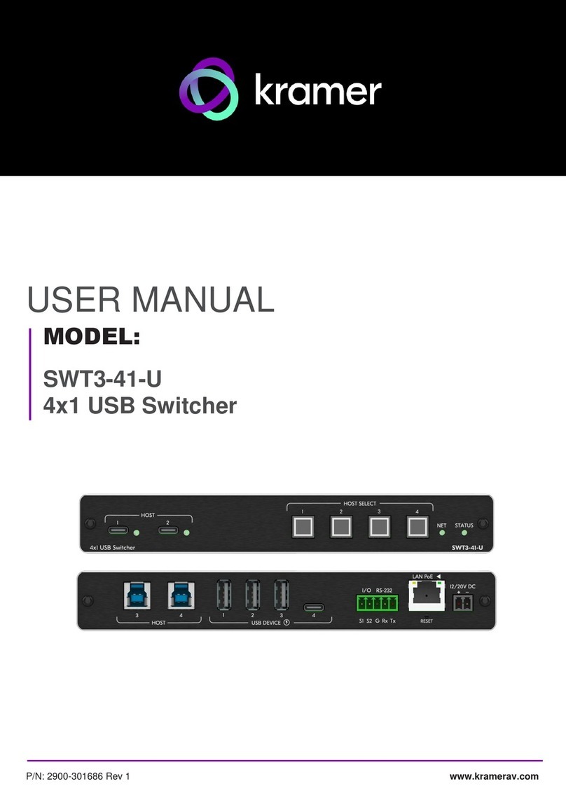
HOST USB B 3.1 Connectors (3 to 4)
Connect to a USB host (for example, a room PC) to communicate with the USB
devices (for example, a PTZ camera) connected to USB device ports on this device
and connect to the LAN.
Connect to a compatible CAT receiver (for example an EXT3-UE-R) or a compatible
CAT splitter (for example an ACC3-12-SP).
Connect to a compatible CAT receiver (for example an EXT3-UE-R).
Connect to the USB local devices (for example, a USB camera, a soundbar,
microphone and so on).
Connect to the USB local devices (for example, a USB camera, a soundbar,
microphone and so on).
Note that this port does not provide Power delivery 2.0.
I/O 2-pin Terminal Block
(S1, S2, G)
Connect to:
•Input-triggering devices (for example, remote buttons or sensors), OR
•Output-triggered devices (for example, remote alarm LED indication).
These GPIO ports may be configured as a digital input, digital output, or analog
input ports.
RS-232 3-pin Terminal Block
Connector
(G, Rx, Tx)
Connect to:
•RS-232 controlled device (for example, a PTZ USB camera) for its remote IP
control by a controller (for example, an SL-240C), OR
•RS-232 control port of a controller (for example, an SL-240C) for extension via
a CAT port, OR
•PC RS-232 port for controlling the device.
Connect to LAN. The device accepts power from the LAN port (PoE).
A LAN-enabled connection on the selected USB-C port is LAN-switched via this
LAN port.
12/20V DC Power Connector
Use the included +12V 2A connector for powering the unit, or a +20V DC 6A power
adapter (purchased separately) for also powering and charging the source device
connected to the USB-C HOST ports on the front panel.
For restoring factory default settings, press the RESET button and connect power to
device (keep pressing longer than 6sec after power connection)
AUDIO IN 5-pin Terminal Block
Connector
Connect to a balanced, stereo audio source (for example, from the server) for
extension via the CAT ports.
Step 3: Mount SWT3-41-U-T
Install SWT3-41-U-T using one of the following methods:
•Attach the rubber feet and place the unit on a flat surface.
•Fasten a bracket (included) on each side of the unit and attach it to a flat surface
(see www.kramerav.com/downloads/SWT3-41-U-T).
•Mount the unit in a rack using the recommended rack adapter
(see www.kramerav.com/product/SWT3-41-U-T).
•Ensure that the environment (e.g., maximum ambient temperature &
air flow) is compatible for the device.
•Avoid uneven mechanical loading.
•Appropriate consideration of equipment nameplate ratings should
be used for avoiding overloading of the circuits.
•Reliable earthing of rack-mounted equipment should be maintained.
•Maximum mounting height for the device is 2 meters.
