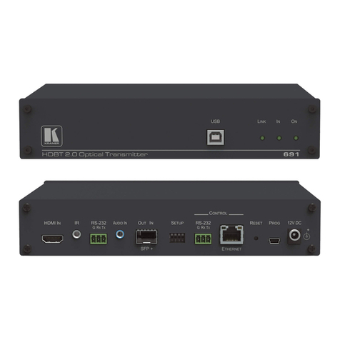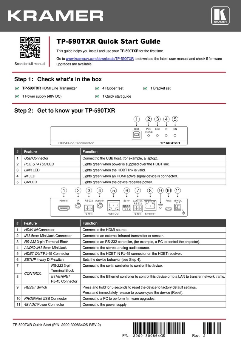
Lights blue to indicate gateway activity ofany RS-232, IRor CEC signals sent, as selected
in the embedded web pages.
Lights blue to indicate gateway activity ofany RS-232, IRor CEC signals received, as
selected in the embedded web pages.
Lights green when power is received over the TP connection.
Lights greenwhen the HDBT link is valid.
Lights green whenthe device receives power.
Connect to anHDMI acceptor.
IR 3.5mm Mini Jack Connector
Connect to an external IR emitter to control a local device from the transmitter (TP-594Txr)
side.
Connect to an IR sensor to control a remote device connected to the TP-594Txr
transmitter.
RS-232 3-pin Terminal Block
Connector
Connect to an RS-232 deviceto be controlled, for example, a projector.
AUDIO 5-pin Terminal Block
Connector
Connect to astereo balanced audio source or anacceptor (the connection type is defined
via the embedded web pages):
Connect an audio acceptor to output theaudio signal received from the audio source on
the transmitter side via the HDBT line.
Connect an audio sourcetoextend an audio signal from TP-594Rxr tothe audio acceptor
on theTP-594Txr via the HDBT line.
1 digital audio on a TOSLINK optical female connector for digitalaudio input and extension
to thetransmitter.
Connect to the RJ-45 HDBT OUT connector on atransmitter (for example,
TP-594Txr or TP-590Txr) to extend the signals between TP-594Rxr and thetransmitter.
Set the operation DIP-switches(see Step 4:Connect the inputsand outputs).
CONTROL RS-232 3-pin Terminal
Block Connector
Connect to a PC tocontrol the device.
CONTROL ETHERNET RJ-45
Connector
Connect to a PC tocontrol the device or for LAN extension.
Press and hold toreset settings to factory default values.
Connect to aUSB memory device to upgrade the firmware.
12V DC connector for powering the unitwhen unit is notpowered via the HDBT link by the
transmitter.
Step 3: Mount TP-594Txr/TP-594Rxr
Install TP-594Txr/TP-594Rxr using oneof the following methods:
•Attach the rubber feet and place the unit on a flat surface.
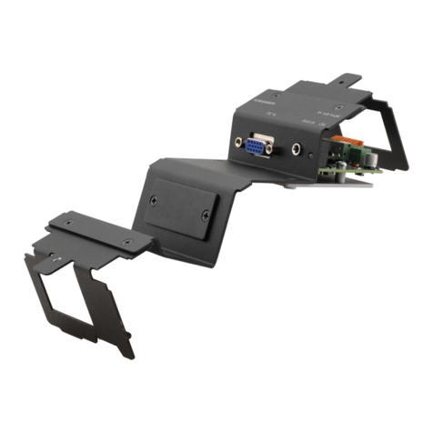
•Fasten a bracket (included) on each side of the unit and attach it to a flat
surface (see www.kramerav.com/downloads/TP-594Txr.).
•Mount the unit in a rack using the recommended
rack adapter
(see www.kramerav.com/product/TP-594Txr).
•Ensure that the environment (e.g., maximum ambient temperature &
air flow) is compatible for the device.
•Avoid uneven mechanical loading.
•Appropriate consideration of equipment nameplate ratings should be
used for avoiding overloading of the circuits.
•Reliable earthing of rack-mounted equipment should be maintained.
