Kramer TP-121EDID User manual
Other Kramer Transmitter manuals
Kramer
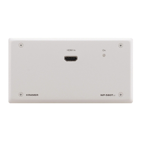
Kramer WP-580Txr User manual

Kramer
Kramer TP-112HD User manual

Kramer
Kramer RC-116 User manual
Kramer
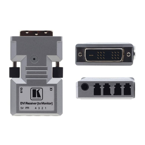
Kramer 610R User manual

Kramer
Kramer TP-580CT User manual
Kramer
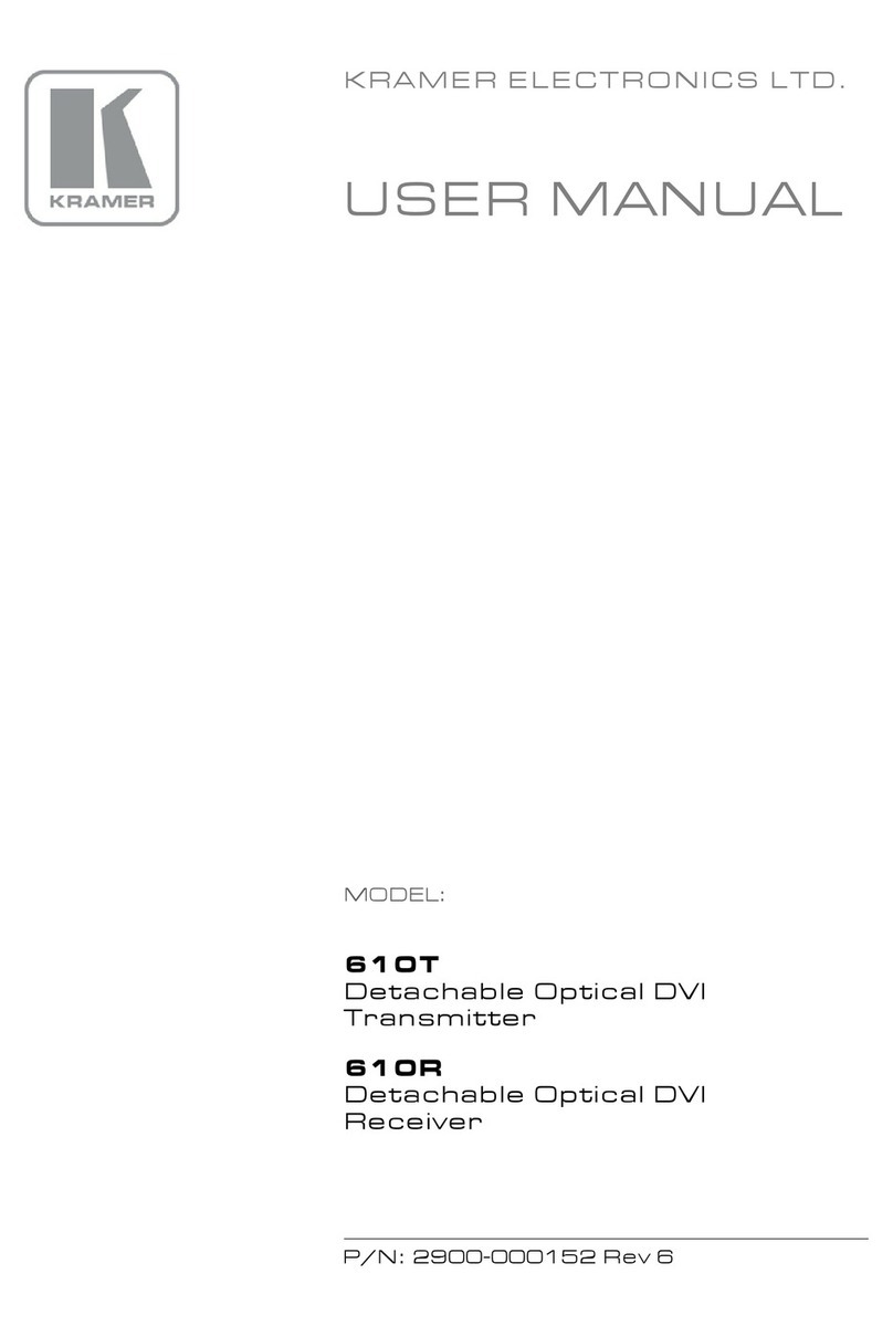
Kramer TP-205A User manual
Kramer
Kramer 610T User manual

Kramer
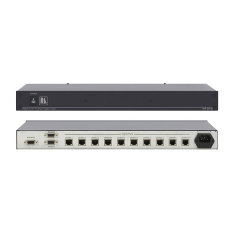
Kramer TP-45EDID User manual
Kramer
Kramer TP-210 User manual

Kramer
Kramer 691 User manual
Kramer
Kramer F-121 User manual

Kramer
Kramer TP-583Txr User manual
Kramer
Kramer Cobra T2 User manual
Kramer
Kramer 650T User manual
Kramer
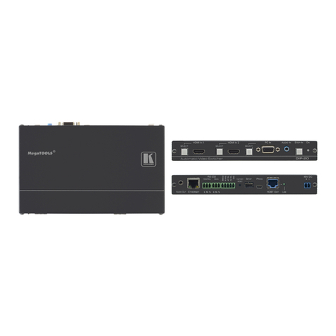
Kramer DIP-20 User manual
Kramer
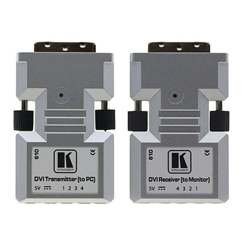
Kramer 610T User manual

Kramer
Kramer TP-145 User manual

Kramer
Kramer TP-125 User manual
Kramer
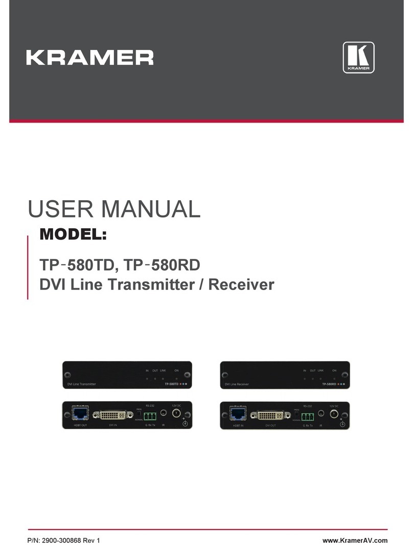
Kramer TP-580TD User manual

Kramer
Kramer 617T User manual
Popular Transmitter manuals by other brands

Dejero
Dejero EnGo 3x manual

Rosemount
Rosemount 4600 Reference manual

Speaka Professional
Speaka Professional 2342740 operating instructions

trubomat
trubomat GAB 1000 instruction manual

Teledyne Analytical Instruments
Teledyne Analytical Instruments LXT-380 instructions

Rondish
Rondish UT-11 quick start guide


