manuals.online logo
Brands
  1. Home
  2. •
  3. Brands
  4. •
  5. KROHNE
  6. •
  7. Measuring Instrument
  8. •
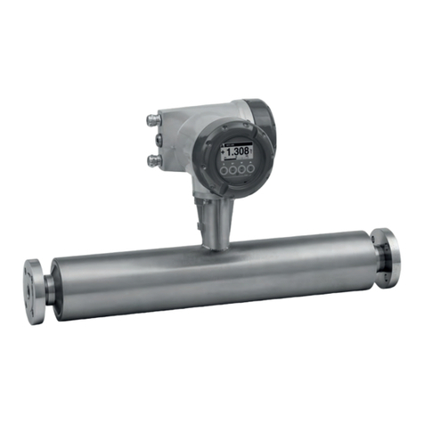
  9. KROHNE OPTISONIC 3400 F User manual

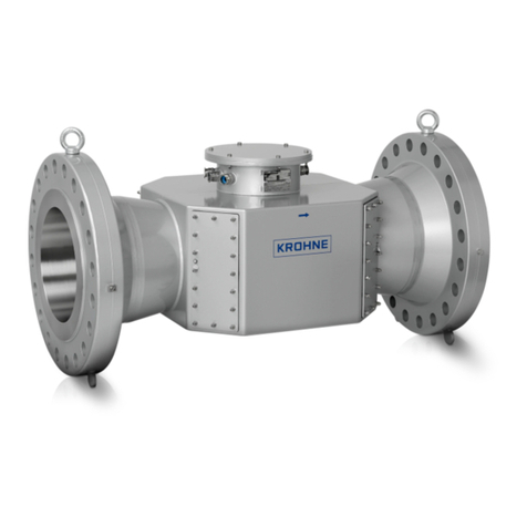
KROHNE OPTISONIC 3400 F User manual

For initial set up, we strongly recommend that you also refer to the relevant manual!
Device version(s)
Installation position
G see below "2D and 3D bends"
04/2023 - 4009785401 - OPTISONIC 3400 F R06 en 1

Quick Start
Installation, assembly, start-up and maintenance may only be performed by appropriately trained personnel. Check
the nameplate for correct operating conditions.
XYZ (3D bends upstream) :

● Avoid the risk of ignition as a result of electrostatic charging. Do not use the device in areas, with processes
that generate high charges, with mechanical friction and cutting process, near electrostatic painting systems
(spraying of electrons), with exposure of airborne powder or dust particles (pressurized systems).
Ex ► Type Examination Certificate: KIWA 15 ATEX 0007 X / IECEx KIWA 15.0033X
UKCA : CSAE 22UKEX1056X / CSAE 22UKEX1058X
OPTISONIC 3400 F 1 Installation The actual installation depends on the version ordered. The illustrations
show installation of a separate (remote) version
Inlet, outlet and T-section
Multi purpose, all-round, ultrasonic flowmeter for liquids in all industrial
processes
This instrument complies with requirements of Low Voltage Directive. Instruments must not be connected to power
supply before reading instructions described in the manual.
G
The responsibility as to the suitability, intended use and corrosion resistance of the used materials against the
measured fluid of this device rests solely with the operator.
This instrument complies with the requirements of Pressure Equipment Directive. Please refer to the nameplate for
operating condition limits. Instruments must not be pressurised before reading instructions described in the manual.
XY (2D bends upstream) : 
For use in hazardous areas, special codes and regulations are applicable. Instruments must not be connected
to power supply before reading instructions described in the supplementary manual.
● The instructions provided with the product shall be followed in detail to assure safe operation.
Installation: Depends on 2D/3D bends
upstream
Special conditions to be observed
● For ambient and process temperatures, specific product and electrical data, see Ex manual or certificate.
● For dimensions and details of the flameproof joints, the manufacturer shall be contacted.
● The tensile strength of the special fasteners is at least 700 N/mm² (property class A2-70 / A4-70).
General Device nameplate
Check the manual for more details on installation
options.

Maximum ambient and process temperatures are
depending on version (e.g liner material, size),
temperature and protection class
and maximum surface temperature of sensor.

Consult the manual for XT / Cryogenic version
(high/low temperature) Check the device nameplate to ensure that the device is delivered
according to your order.
Wall mounting
3100...230 VAC (-15% / +10%), 22VA
24VDC (-55% / +30%), 12W
1Sensor cable connections
12I/O connections
3Mains supply connection
4Insert cable(s) into terminal compartment
5Marking on cable
6Tool for releasing connectors
7Grounding clamps
6
4
5 7
04/2023 - 4009785401 - OPTISONIC 3400 F R06 en 2
2 Electrical connection
All work on the electrical connections may only be carried out with the power disconnected. Take note
of the voltage data on the nameplate! Observe the national regulations for electrical installations!
Observe without fail the local occupational health and safety regulations. Any work done on the
electrical components of the measuring device may only be carried out by properly trained specialists.
Power supply - grounding
The device must be grounded in accordance with
regulations in order to protect personnel against
electric shocks.
Electrical connections signal converter
Pipe mounting
Thermal insulation
Avoid vibration
24VAC/DC (AC: -15% / +10%; DC: -25% / +30%),
22VA or 12W
2
Check the manual for more details on installation options.
Connect the cable on connector with similar
numeral marking
Connection diagram
Current output active Ia (basic I/O) Pulse/frequency output passive Pp (modular I/O)
Current output passive Ip (basic I/O) Pulse/ frequency output passive PN, NAMUR (modular I/O)
Status output/limit switch passive Sp (basic I/O) Status output/limit switch passive Sp, (modular I/O)
Pulse/frequency output active Pa (modular I/O) Control input active CN to NAMUR, (modular I/O)
04/2023 - 4009785401 - OPTISONIC 3400 F R06 en 3
Control input active Ca, (modular I/O)
Connect the cable on connector with similar numeral marking
Signal cable to flow sensor
Cryogenic and XXT version Standard version
For devices used in hazardous areas, additional safety notes apply; please refer to the Ex documentation.
Refer to the manual for connection of Ex (/i ) acc. to NAMUR
2 Electrical connection Observe connection polarity
Pulse/frequency output passive Pp (basic I/O) Status output/limit switch active Sa, (modular I/O)
Control input passive Cp (basic I/O) Status output/limit switch SN, NAMUR, (modular I/O)
Current output active Ia (modular/Ex i I/O)
Measuring mode
Select menu Select Submenu Functions
Press > 2.5 s   
A
   
www.krohne.com
04/2023 - 4009785401 - OPTISONIC 3400 F R06 en 4
Status message
Tag number
Measured variable
Signal strength
Operating keys (operation with
open housing)
3 Quick Setup
A1 language
A2 tag
A3.1 reset errors
A3.2 totalizer 1
A3.3 totalizer 2
A3.4 totalizer 3
A3 reset
Contact
Scan the code on the nameplate or scan the following code
and enter the serial number.
A5.4 low flow cutoff
Select your country from the region / language selector
to view your local KROHNE contact details on:
A6 GDC IR interface
A4.5 time constant
A5 Digital Outputs
A5.1 measurement
A5.2 pulse value unit
A5.3 value p. pulse
Download documents/software
A4 analog Outputs
A4.1 measurement
A4.2 unit
A4.3 range
A4.4 low flow cutoff








Other KROHNE Measuring Instrument manuals

KROHNE VFM 5090 I User manual

KROHNE

KROHNE VFM 5090 I User manual

KROHNE Optisonic 6300 P User manual

KROHNE

KROHNE Optisonic 6300 P User manual

KROHNE BM 700 User manual

KROHNE

KROHNE BM 700 User manual

KROHNE OPTISYS CL 1100 User manual

KROHNE

KROHNE OPTISYS CL 1100 User manual

KROHNE ALTOSONIC UFM 610 P User manual

KROHNE

KROHNE ALTOSONIC UFM 610 P User manual

KROHNE WATERFLUX 3070 User manual

KROHNE

KROHNE WATERFLUX 3070 User manual

KROHNE IFC100 User manual

KROHNE

KROHNE IFC100 User manual

KROHNE OPTIWAVE 5200 C Wiring diagram

KROHNE

KROHNE OPTIWAVE 5200 C Wiring diagram

KROHNE OPTIWAVE 5200 C Wiring diagram

KROHNE

KROHNE OPTIWAVE 5200 C Wiring diagram

KROHNE OPTIFLEX 1100 C User manual

KROHNE

KROHNE OPTIFLEX 1100 C User manual

KROHNE OPTIFLUX 5000 User manual

KROHNE

KROHNE OPTIFLUX 5000 User manual

KROHNE OPTIMASS 2400 User manual

KROHNE

KROHNE OPTIMASS 2400 User manual

KROHNE OPTIWAVE 6300 C User manual

KROHNE

KROHNE OPTIWAVE 6300 C User manual

KROHNE ALTOSONIC V User manual

KROHNE

KROHNE ALTOSONIC V User manual

KROHNE BM 70 A User manual

KROHNE

KROHNE BM 70 A User manual

KROHNE OPTIMASS Series User manual

KROHNE

KROHNE OPTIMASS Series User manual

KROHNE H250 M9 Wiring diagram

KROHNE

KROHNE H250 M9 Wiring diagram

KROHNE SDA User manual

KROHNE

KROHNE SDA User manual

KROHNE OPTISONIC 6300 User manual

KROHNE

KROHNE OPTISONIC 6300 User manual

KROHNE OPTIWAVE 7500 C User manual

KROHNE

KROHNE OPTIWAVE 7500 C User manual

KROHNE OPTISONIC 7300 Wiring diagram

KROHNE

KROHNE OPTISONIC 7300 Wiring diagram

KROHNE OPTIWAVE 8300 User manual

KROHNE

KROHNE OPTIWAVE 8300 User manual

KROHNE OPTIFLEX 2200 Wiring diagram

KROHNE

KROHNE OPTIFLEX 2200 Wiring diagram

KROHNE DWM 2000 D User manual

KROHNE

KROHNE DWM 2000 D User manual

Popular Measuring Instrument manuals by other brands

Chauvin Arnox C.A 6543 user manual

Chauvin Arnox

Chauvin Arnox C.A 6543 user manual

BRIGHT BlueEye Ex-D operating manual

BRIGHT

BRIGHT BlueEye Ex-D operating manual

Dosy Test Center TC-4001-P instruction manual

Dosy

Dosy Test Center TC-4001-P instruction manual

Eurotron MicroCal 20 Series instruction manual

Eurotron

Eurotron MicroCal 20 Series instruction manual

Trotec BQ30 operating manual

Trotec

Trotec BQ30 operating manual

Burkert 8071 operating instructions

Burkert

Burkert 8071 operating instructions

Flin Energy GPRS user manual

Flin Energy

Flin Energy GPRS user manual

MIJA Critical Alert Universal user manual

MIJA

MIJA Critical Alert Universal user manual

Gigahertz Solutions HFW59D manual

Gigahertz Solutions

Gigahertz Solutions HFW59D manual

Textron Greenlee CM-600 instruction manual

Textron

Textron Greenlee CM-600 instruction manual

LEWA ecosmart LCA Operating	 instruction

LEWA

LEWA ecosmart LCA Operating instruction

Connected Inventions Connected AirWits IAQ user manual

Connected Inventions

Connected Inventions Connected AirWits IAQ user manual

Milwaukee 48-22-9802 Operator's manual

Milwaukee

Milwaukee 48-22-9802 Operator's manual

493K K-METRON User instructions

493K

493K K-METRON User instructions

ENDA EPA141 manual

ENDA

ENDA EPA141 manual

Murata 4284A manual

Murata

Murata 4284A manual

Satel K-1 quick start guide

Satel

Satel K-1 quick start guide

Badger Meter MN Series Instruction and operation manual

Badger Meter

Badger Meter MN Series Instruction and operation manual

manuals.online logo
manuals.online logoBrands
  • About & Mission
  • Contact us
  • Privacy Policy
  • Terms and Conditions

Copyright 2025 Manuals.Online. All Rights Reserved.