Kroll LH Series Manual

TECHNICAL INFORMATION ASSEMBLY, USE AND
MAINTENANCE INSTRUCTIONS
Water-Fed Fan Heaters
SERIES LH / LH-X

Dear Customer,
Thank you for choosing a Series LH / LH-X water-fed fan heater, an innovative, modern, high quality, high
efficiency product that will provide you with long-lasting comfort, silent running and safety; we recommend
that your fan heater be serviced by a Kroll Technical Service only so as to ensure optimum performance at
all times, low running costs and immediate availability of original spare parts.
Thank you
Kroll GmbH
CONFORMITY
LH / LH-X water-fed fan heaters comply with:
• EEC Machinery Directives 98/37
• EEC Low Voltage Directive 73/23
RANGE
Type Commercial name Product code for equipments
with case pre-painted – EDV
Number
Product code for equipments
with case in stainless steel –
EDV Number
1 LH120 038972-01 038988-01
2 LH130 038973-01 038989-01
3 LH220 038974-01 038990-01
4 LH230 038975-01 038991-01
7 LH320 038976-01 038992-01
8 LH330 038977-01 038993-01
9 LH420 038978-01 038994-01
10 LH430 038979-01 038995-01
11 LH520 038980-01 038996-01
12 LH530 038981-01 038997-01
13 LH620 038982-01 038998-01
14 LH630 038983-01 038999-01
15 LH720 038984-01 039000-01
16 LH730 038985-01 039001-01
17 LH920 038986-01 039002-01
18 LH930 038987-01 039003-01
WARRANTY
The LH / LH-x fan heater has a specific warranty that begins on the date of purchase. The customer must retain
documents as proof of purchase. If the customer is unable to provide such proof, the Warranty period shall begin as from
the date of production of the unit.
The terms of the Warranty are set out in detail on the WARRANTY CERTIFICATE supplied with the unit. Please read
this certificate carefully.
2

INDEX
CONFORMITY Page. 2
RANGE 2
WARRANTY 2
INDEX 3
GENERAL INFORMATION Page. 4
IMPORTANT SAFETY REGULATIONS “ 5
DESCRIPTION OF UNIT “ 5
PRODUCT RECEPTION Page. 5
HANDLING AND TRANSPORT “ 6
REMOVING THE PACKAGING “ 6
IDENTIFICATION “ 7
OVERALL DIMENSIONS AND WEIGHT “ 7
STRUCTURE “ 8
TECHNICAL DATA “ 9
PERFORMANCES WITH WATER AT 90-70°C 10
PERFORMANCES WITH WATER AT 85-70°C 18
PERFORMANCES WITH WATER AT 50-40°C 26
ACCESSORIES “ 34
POSITIONING “ 34
SHELF MOUNTING “ 36
INSTALLING THE VERTICAL FIN KIT “ 37
CEILING MOUNTING KIT “ 38
WATER COUPLING DIMENSIONS “ 38
WATER CIRCUIT DIAGRAM 38
INVERTING THE WATER CONNECTIONS “ 39
WATER CONNECTIONS “ 39
ELECTRICAL CONNECTIONS “ 40
ELECTRICAL CONNECTIONS PLAN FOR TYPE 1 - 12 41
ELECTRICAL CONNECTIONS PLAN FOR TYPE 13 - 18 41
ELECTRICAL CONNECTIONS PLAN FOR TYPE 13 - 18 42
ELECTRICAL PLAN FOR MOTOR WINDINGS 42
ELECTRICAL CONNECTIONS PLAN FOR TYPE 15 - 18 43
ELECTRICAL CONNECTIONS PLAN FOR TYPE 15 - 18 44
ELECTRICAL CONNECTIONS PLAN FOR
ACCESSORIES
45
FILLING – EMPTYNG THE UNIT 45
PREPARING FOR START-UP “ 46
FIN ADJUSTMENT 46
FIRST-TIME START-UP “ 46
CHECKS DURING AND AFTER FIRST-TIME START-UP “ 47
SWITCHING OFF FOR LONG PERIODS 47
MANTEINANCE 47
TROUBLESHOOTING “ 47
The following symbols are used in some parts of this handbook:
WARNING = tasks requiring special caution and
adequate training
FORBIDDEN = actions that MUST NOT be performed.
This manual has 52 pages.

GENERAL INFORMATION
This manual is an integral part of the product. Always
make sure the unit is accompanied by this manual so
that it can be consulted by the user, installer or any
specialised Assistance Service personnel, even in
the event of sale. If it is damaged or lost, a copy can
be requested from your authorised dealer.
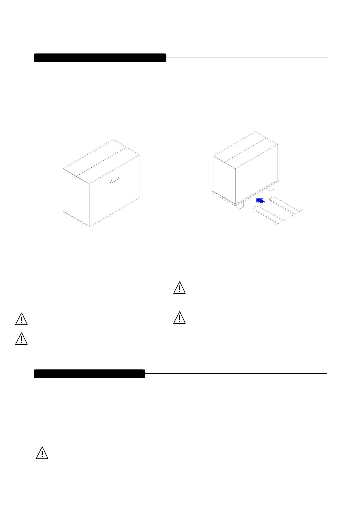
After removing the unit from its packaging make sure
it has not been damaged during transport and that no
parts are missing; if in doubt contact your dealer.
Installation of the water-fed fan heaters must be
carried out by a qualified company. On completion of
installation such company must issue a Declaration
of Conformity stating that installation has been
effected as per the standards in force and in
compliance with the instructions contained in this
manual.
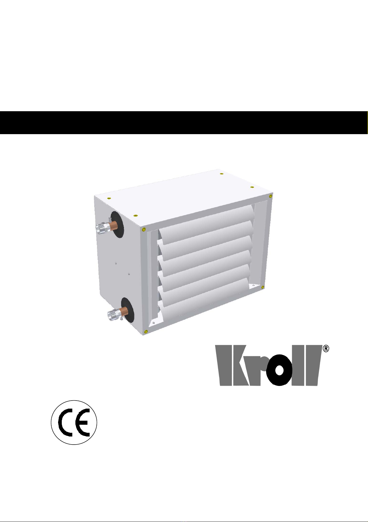
This unit has been designed for indoor heating
purposes only and must only be used for such
purposes in situations compatible with their
performance.
The manufacturer is exonerated from any contractual
or extra-contractual liability regarding damages
caused by incorrect installation, adjustment,
maintenance or improper use.
A too high indoor temperature is both unhealthy and
constitutes a wasteful use of energy. Do not keep
rooms/buildings closed for long periods: periodically
open a window to air the room/building.
If you do not intend to use the unit for a long period
of time you MUST at least do the following:
• Turn the main unit switch and the mains socket
switch to OFF.
• If there is a risk of sub-zero temperatures, drain
the water from the unit.
If the unit has remained idle for a long period, it is
advisable to have it restarted by an authorised
Technical Assistance Service or, in any case, by
professionally qualified personnel.
Use original spare parts only. The Manufacturer cannot
be held liable for any damages caused by improper
use of the unit or the use of non-original parts.
References to laws, directives and regulations are
indicative only and are valid at the time of going to
press. The coming into force of new laws, or
amendments to existing ones does not constitute any
obligation towards third parties on the part of the
Manufacturer.
Repair and/or maintenance work must be carried out
by an Authorised Service Technician or personnel
qualified as described in this manual. Do not modify or
tamper with the heater as dangerous situations may
result The Manufacturer cannot be held liable for any
damages resulting from failure to observe the above.
All connected systems (water supply, electrical
connections etc.) must be secured safely and must not
constitute obstacles or cause personnel to trip up.
The Manufacturer is responsible for ensuring that the
unit complies with the rules, regulations, directives and
standards concerning construction in force at the time
the unit is put on sale. Awareness of, understanding
and observance of legislation and standards regarding
systems design, installation, use and maintenance are,
instead, the exclusive responsibility of the planner,
installer and user.
The Manufacturer cannot be held liable for failure to
observe the instructions contained in this manual, for
the consequences of actions not specifically described
in this manual or for erroneous translations which may
lead to incorrect interpretation.
3

IMPORTANT SAFETY REGULATIONS
It is forbidden for children or unassisted
disabled persons to use this unit.
Never touch the unit if you are barefoot or if any
part of your body is wet.
Before carrying out any cleaning and/or
maintenance work on the unit always disconnect
the unit from the mains power supply by turning the
main switch to OFF.
Any modification to safety or regulation systems is
strictly forbidden without the Manufacturer’s
permission and guidance.
Never tug or detach any wires protruding from the
unit even when the latter is disconnected from the
power supply.
Do not dump packaging (plastic bags, expanded
polystyrene etc.) improperly. Keep such packaging
away from children as it is dangerous. For proper
disposal consult your local authorities.
Do not install the unit in areas with a damp or
“aggressive” atmosphere.
Do not place any objects on the unit or insert any
objects through the cover grating.
Do not touch the heat exchanger battery with naked
hands
Do not use adapters, multiple sockets or extension
leads to connect the unit to the electricity supply.
It is forbidden to install the unit outdoors or where it is
exposed to adverse weather conditions.
DESCRIPTION OF UNIT
Water-fed fan heaters are designed to provide heating
in winter and ventilation in summer. They are ideal for
indoor areas such as shops, workshops and factories.
Hot water produced by a boiler (not supplied with this
unit) flows inside a water-air heat exchanger; an air flow
generated by an electrically powered helical fan flows
through the exchanger. As the air flows through the
exchanger it absorbs the heat contained in the coil and
the air temperature increases. Thus cold air flows into
the exchanger and hot air flows out.
During the summer the fan can be run on its own to
provide ventilation.
GENERAL CONSTRUCTION CHARACTERISTICS
Water-air exchanger
Made of a high-efficiency copper battery with aluminium
fins. Water connection couplings have a manual bleed
valve.
Cover
Made of galvanised, pre-painted sheet metal; attractive,
modern design. Highly compact and versatile.
Helical fan
Made up of a safety grating and a high performance,
silent-running fan unit.
PRODUCT RECEPTION
The unit is sent in a single case and includes:
WATER-FED FAN HEATER
PLASTIC BAG (A) containing:
• Instruction Manual;
• Warranty Certificate;
• Spare Parts catalogne.
A
4

HANDLING AND TRANSPORT
Handling must be done by properly equipped personnel.
All equipment must be suitable to handle the weight of
the unit.
Unit types 1-2-3-4-5-6 are packaged in a cardboard
case with handles to aid transport.
Unit’s types 7-8-9 are packaged in a cardboard case
with a wooden base. Raise the case with a fork-lift truck
by inserting the forks in the special guides hollowed out
in the support beams.
Manual handling (types 1-14)
Handling with a fork-lift truck (types 15-18)
WARNING!
Handling and transport must be carried out with the
utmost care so as to prevent damage to the heater unit
and ensure the safety of the personnel carrying out the
work.
Do not stand near the heater during transport and
handling.
If it is necessary to stack several units always observe
the stacking index: this is shown on the case. Always
align the cases carefully to prevent stack instability.
If the unit has to be handled manually make sure that
the weight of the unit can be lifted and manoeuvred
along the route to be taken by available personnel
without difficulty.
Use of personal safety items (work gloves, hard hat,
work shoes etc.) is recommended.
REMOVING THE PACKAGING
To remove the packaging, proceed as follows:
• Cut the strap (types 7-9 only);
• Open the upper part of the case;
• Remove the inner spacers;
• Pull the unit upwards out of the case.
WARNING!
Do not dump packaging improperly as it is a potential
source of danger. For proper disposal contact your local
authorities.
5

IDENTIFICATION
The water-fed fan heaters can be identified by:
• The TECHNICAL DATA plaque (positioned on the
rear of the unit) which shows the main
technical/performance data.
If the plaque is damaged or lost request a
duplicate from an Authorised Technical Service.
MANUFACTURER IDENTIFICATION
WATER-FED FAN HEATER
Model
Code
Serial n°
Year of construction
Heating cap. output(1) kW
Max air flow rate m3/h
Electrical power supply V – 50 Hz
Max electrical power W
Max electrical current A
Protection rating IP
Max working pressure bar
(1) Water 85-70°C, Air 15°C, U.R. 50%
OVERALL DIMENSIONS AND WEIGHT
6
Technical
data label

Type 1 2 3 4 5 6 7 8 9 10 11 12 13 14 15 16 17 18
A 550 600 650 700 750 800 850 1200 1400 mm
B 400 450 500 550 600 650 700 700 700 mm
C 331 331 331 331 331 331 331 331 331 mm
D 95 115 130 110 120 150 170 170 170 mm
E 79 79 79 79 79 79 79 79 79 mm
F 72 72 72 72 72 72 72 72 72 mm
P 489 539 589 639 689 739 789 1139 1339 mm
∅M6 M6 M6 M6 M6 M6 M6 M6 M6 F
Weight
17.0 18.2 19.2 20.6 22.2 24.8 25.6 27.0 30.5 32.0 32.0 35.7 41.0 44.4 58.7 63.8 70.6 76.3
Kg
Structure of Heater Types 1 - 14
Structure of Heater Types 15 - 18
1. Water-air heat exchanger
2. Side panel, left
3. Side panel, right
4. Upper-lower panel
5. Internal part
6. Fixing part
7. Fixing part
8. Fan(s)
9. Outflow grating
8
9
1
3
2
4
4
5
5
6
6
7
8
8
7
3
6
4 5
9
1
2
5
4

TECHNICAL DATA
GENERAL TECHNICAL DATA TABLE
(1) Data refers to following conditions:
- Water temperature 85-70°C
- Air temperature 15°C
- U.R. 50%
- Atmospheric pressure 1013 mbar
- Max fan speed
(2) Data refers to the following conditions:
- Area unobstructed
- Max fan speed
- Unit installed on wall 3 m above ground with sound pressure measured frontally.
(3) RPM variations attained via use of special accessories (available as an optional). RPM figures are
average values as RPM varies from model to model.
FAN
TYPE
HEATING CAPACITY(1)
Kw kcal/h
NUMBER OF
RANGE
N°
NUMBER OF FANS
N°
DIAMETER.
FAN SPEED
rpm
MAX-MED-MIN
V/min’
MAX AIR
DELIVERY
RATE
m3/h
AIR
OUTFLOW
RANGE
m
AIR OUTFLOW
TEMP (1)
°C
WATER
SIDE
HEAD
LOSS
kPa
WATER
FLOW
RATE
litres/h
ELECTRICAL
POWER SUPPLY
PROTECTION
DEGREE
ELECTRICAL
POWER
W
MAX
ELECTRIC
A
L CURREN
T
A
NOISE LEVEL2)
dB(A)
(2)
KW kcal/h Nr. Nr mm V/min’ m3/h m °C kPa Lit./h
IP W A MAX MED MIN
1 13,3 11450 2 300 1750 22 38 26 785
54 80 0,40 50 47 41
2 17,3 14900 3 300 1550 17 47 20 1020
54 80 0,40 50 47 41
3 17,7 15250 2 315 2450 25 36 17 1044
54 95 0,40 51 47 45
4 23,8 20450 3 315 2300 19 45 20 1401
54 95 0,40 51 47 45
5 22 18950 2 330 2800 31 38 30 1296
230V~ 54 130 0,58 52 50 43
6 28,5 24550 3 1 330 2550 25 47 17 1680
50 H z 54 130 0,58 52 50 43
7 27,4 23550 2 350 3600 31 37 24 1612
54 140 0,70 53 49 43
8 35,4 31300 3 350 3400 25 46 19 2141
54 140 0,70 53 49 43
9 31,9 27400 2 400 3950 32 39 20 1876
54 180 0,80 53 49 43
10 42,7 36750 3 400 3900 24 47 13 2514
54 180 0,80 53 49 43
11 39,1 33600 2 420 5200 33 37 13 2300
44 150 1,40 53 49 47
12 52,4 45100 3 420
1400 - 900 - 700 (3)
4900 26 46 16 3086
44 150 1,40 53 49 47
13 47,4 40800 2 600 6700 39 36 14 2793
54 245 1,04 52 - 46
14 63 54150 3 600 6200 37 45 12 3707
400 V~ 54 245 1,04 52 - 46
15 67,7 58200 2 450 8500 38 38 11 3985
50Hz3N 54 260 1,40 54 - 49
16 87,8 75550 3 2 450 7700 32 48 9 5173
54 260 1,40 54 - 49
17 88,8 76400 2 600 12550 40 36 21 5229
54 490 2,08 53 - 48
18 115 98800 3
600
900 - 700 (3)
10900 38 46 17 6764 54 490 2
,
08 53 - 48
UNOBSTRUCTED AREA SOUND PRESSURE MEASUREMENT DIAGRA
M
9

TYPES 1 AND 2, ELECTRICAL POWER SUPPLY SINGLE-PHASE 230 V – 50 Hz, WATER TEMP. DROP 90-70°C
Fan heater type 1 at maximum fan speed with water 90 – 70°C
Air intake temperature 15 20 25 °C
Thermal output 13,7 12,5 11,3
kW
11.750 10.750 9.750
Kcal/h
Air flow rate 1.750 m3/h
Sound pressure level(1) 50 dB(A)
Air outlet temperature 38 42 45
°C
Water side head loss 16 14 12
kPa
Water flow rate 605 533 502
l/h
Fan heater type 1 at medium fan speed with water 90 – 70°C
Air intake temperature 15 20 25 °C
Thermal output 12,0 10,9 9,9
kW
10.300 9.400 8.500
Kcal/h
Air flow rate 1.250 m3/h
Sound pressure level(1) 47 dB(A)
Air outlet temperature 43 46 49
°C
Water side head loss 13 11 9
kPa
Water flow rate 530 485 440
l/h
Fan heater type 1 at minimum fan speed with water 90 – 70°C
Air intake temperature 15 20 25 °C
Thermal output 10,5 9,6 8,7
kW
9.000 8.250 7.500
Kcal/h
Air flow rate 900 m3/h
Sound pressure level(1) 41 dB(A)
Air outlet temperature 49 51 54
°C
Water side head loss 10 9 7
kPa
Water flow rate 463 424 385
l/h
Fan heater type 2 at maximum fan speed with water 90 – 70°C
Air intake temperature 15 20 25 °C
Thermal output 17,8 16,3 14,8
kW
15.350 14.050 12.750
Kcal/h
Air flow rate 1.550 m3/h
Sound pressure level(1) 50 DB(A)
Air outlet temperature 48 51 54
°C
Water side head loss 13 11 9
kPa
Water flow rate 790 722 656
l/h
Fan heater type 2 at medium fan speed with water 90 – 70°C
Air intake temperature 15 20 25 °C
Thermal output 15,3 14,1 12,7
kW
13.200 12.100 10.950
Kcal/h
Air flow rate 1.150 M3/h
Sound pressure level(1) 47 dB(A)
Air outlet temperature 54 57 59
°C
Water side head loss 10 8 7
kPa
Water flow rate 680 621 564
l/h
Fan heater type 2 at minimum fan speed with water 90 – 70°C
Air intake temperature 15 20 25 °C
Thermal output 13,0 11,9 10,8
kW
11.200 10.250 9.300
Kcal/h
Air flow rate 850 m3/h
Sound pressure level(1) 41 Db(A)
Air outlet temperature 60 62 64
°C
Water side head loss 7 6 5
kPa
Water flow rate 577 527 478
l/h
(1) Data refers to the following conditions:
- Area unobstructed
- Unit installed on wall 3 m above ground with sound pressure measured frontally.
10

TYPES 3 AND 4, ELECTRICAL POWER SUPPLY SINGLE-PHASE 230 V – 50 Hz, WATER TEMP. DROP 90-70°C
Fan heater type 3 at maximum fan speed with water 90 – 70°C
Air intake temperature 15 20 25 °C
Thermal output 18,1 16,6 15,1
kW
15.600 14.300 12.950
Kcal/h
Air flow rate 2.450 m3/h
Sound pressure level(1) 51 dB(A)
Air outlet temperature 37 40 44
°C
Water side head loss 11 9 8
kPa
Water flow rate 804 735 667
l/h
Fan heater type 3 at medium fan speed with water 90 – 70°C
Air intake temperature 15 20 25 °C
Thermal output 17,1 15,6 14,2
kW
14.700 13.450 12.200
Kcal/h
Air flow rate 2.050 m3/h
Sound pressure level(1) 47 dB(A)
Air outlet temperature 39 43 46
°C
Water side head loss 10 8 7
kPa
Water flow rate 756 692 627
l/h
Fan heater type 3 at minimum fan speed with water 90 – 70°C
Air intake temperature 15 20 25 °C
Thermal output 16,6 15,2 13,8
kW
14.300 13.050 11.850
Kcal/h
Air flow rate 1.900 m3/h
Sound pressure level(1) 45 dB(A)
Air outlet temperature 40 44 47
°C
Water side head loss 9 8 7
kPa
Water flow rate 735 672 609
l/h
Fan heater type 4 at maximum fan speed with water 90 – 70°C
Air intake temperature 15 20 25 °C
Thermal output 24,5 22,4 20,3
kW
21.050 19.250 17.500
Kcal/h
Air flow rate 2.300 m3/h
Sound pressure level(1) 51 dB(A)
Air outlet temperature 46 49 52
°C
Water side head loss 12 11 9
kPa
Water flow rate 1.084 991 899
l/h
Fan heater type 4 at medium fan speed with water 90 – 70°C
Air intake temperature 15 20 25 °C
Thermal output 22,3 20,3 18,5
kW
19.150 17.500 15.900
Kcal/h
Air flow rate 1.850 m3/h
Sound pressure level(1) 47 dB(A)
Air outlet temperature 50 53 55
°C
Water side head loss 10 9 8
kPa
Water flow rate 985 901 817
l/h
Fan heater type 4 at minimum fan speed with water 90 – 70°C
Air intake temperature 15 20 25 °C
Thermal output 20,5 18,7 17,0
kW
17.600 16.100 14.600
Kcal/h
Air flow rate 1550 m3/h
Sound pressure level(1) 45 dB(A)
Air outlet temperature 53 56 58
°C
Water side head loss 9 8 6
kPa
Water flow rate 906 828 752
l/h
(1) Data refers to the following conditions:
- Area unobstructed
- Unit installed on wall 3 m above ground with sound pressure measured frontally..
11

TYPES 5 AND 6, ELECTRICAL POWER SUPPLY SINGLE-PHASE 230 V – 50 Hz, WATER TEMP. DROP 90-70°C
Fan heater type 5 at maximum fan speed with water 90 – 70°C
Air intake temperature 15 20 25 °C
Thermal output 22,6 20,8 18,8
kW
19.450 17.850 16.200
Kcal/h
Air flow rate 2.800 m3/h
Sound pressure level(1) 52 dB(A)
Air outlet temperature 38 42 45
°C
Water side head loss 19 16 14
kPa
Water flow rate 1.002 917 833
l/h
Fan heater type 5 at medium fan speed with water 90 – 70°C
Air intake temperature 15 20 25 °C
Thermal output 20,0 18,3 16,6
kW
17.200 15.750 14.300
Kcal/h
Air flow rate 2.050 m3/h
Sound pressure level(1) 50 dB(A)
Air outlet temperature 43 46 49
°C
Water side head loss 15 13 11
kPa
Water flow rate 884 809 735
l/h
Fan heater type 5 at minimum fan speed with water 90 – 70°C
Air intake temperature 15 20 25 °C
Thermal output 18,1 16,5 15,0
kW
15.550 14.200 12.900
Kcal/h
Air flow rate 1.650 m3/h
Sound pressure level(1) 43 dB(A)
Air outlet temperature 47 50 53
°C
Water side head loss 13 11 9
kPa
Water flow rate 799 732 664
l/h
Fan heater type 6 at maximum fan speed with water 90 – 70°C
Air intake temperature 15 20 25 °C
Thermal output 29,4 26,9 24,4
kW
25.300 23.150 21.000
Kcal/h
Air flow rate 2.550 m3/h
Sound pressure level(1) 52 dB(A)
Air outlet temperature 48 51 54
°C
Water side head loss 11 9 8
kPa
Water flow rate 1.301 1.190 1.080
l/h
Fan heater type 6 at medium fan speed with water 90 – 70°C
Air intake temperature 15 20 25 °C
Thermal output 25,3 23,2 21,0
kW
21.800 19.950 18.100
Kcal/h
Air flow rate 1.900 m3/h
Sound pressure level(1) 50 dB(A)
Air outlet temperature 54 57 59
°C
Water side head loss 9 7 6
kPa
Water flow rate 1.122 1.026 931
l/h
Fan heater type 6 at minimum fan speed with water 90 – 70°C
Air intake temperature 15 20 25 °C
Thermal output 22,1 20,2 18,3
kW
19.000 17.350 15.750
Kcal/h
Air flow rate 1.450 m3/h
Sound pressure level(1) 43 dB(A)
Air outlet temperature 60 61 63
°C
Water side head loss 7 6 5
kPa
Water flow rate 977 893 810
l/h
(1) Data refers to the following conditions:
- Area unobstructed
- Unit installed on wall 3 m above ground with sound pressure measured frontally.
12

TYPES 7 AND 8, ELECTRICAL POWER SUPPLY SINGLE-PHASE 230 V – 50 Hz, WATER TEMP. DROP 90-70°C
Fan heater type 7 at maximum fan speed with water 90 – 70°C
Air intake temperature 15 20 25 °C
Thermal output 28,1 25,8 23,4
kW
24.200 22.150 20.100
Kcal/h
Air flow rate 3.600 m3/h
Sound pressure level(1) 53 dB(A)
Air outlet temperature 38 41 45
°C
Water side head loss 15 13 11
kPa
Water flow rate 1.244 1.139 1.034
l/h
Fan heater type 7 at medium fan speed with water 90 – 70°C
Air intake temperature 15 20 25 °C
Thermal output 23,7 21,7 19,7
kW
20.400 18.650 16.950
Kcal/h
Air flow rate 2.350 m3/h
Sound pressure level(1) 49 dB(A)
Air outlet temperature 45 48 51
°C
Water side head loss 11 9 8
kPa
Water flow rate 1.048 959 871
l/h
Fan heater type 7 at minimum fan speed with water 90 – 70°C
Air intake temperature 15 20 25 °C
Thermal output 20,3 18,6 16,9
kW
17.500 16.000 14.550
Kcal/h
Air flow rate 1650 m3/h
Sound pressure level(1) 43 dB(A)
Air outlet temperature 51 53 56
°C
Water side head loss 8 7 6
kPa
Water flow rate 900 824 748
l/h
Fan heater type 8 at maximum fan speed with water 90 – 70°C
Air intake temperature 15 20 25 °C
Thermal output 37,4 34,3 31,1
kW
32.200 29.500 26.750
Kcal/h
Air flow rate 3400 m3/h
Sound pressure level(1) 53 dB(A)
Air outlet temperature 47 50 53
°C
Water side head loss 12 10 9
kPa
Water flow rate 1.658 1.516 1.376
l/h
Fan heater type 8 at medium fan speed with water 90 – 70°C
Air intake temperature 15 20 25 °C
Thermal output 28,9 26,5 24,0
kW
24.850 22.750 20.650
Kcal/h
Air flow rate 2000 m3/h
Sound pressure level(1) 49 dB(A)
Air outlet temperature 58 60 62
°C
Water side head loss 8 7 6
kPa
Water flow rate 1.279 1.169 1.061
l/h
Fan heater type 8 at minimum fan speed with water 90 – 70°C
Air intake temperature 15 20 25 °C
Thermal output 23,3 21,3 19,4
kW
20.050 18.350 16.650
Kcal/h
Air flow rate 1.350 m3/h
Sound pressure level(1) 43 dB(A)
Air outlet temperature 65 67 68
°C
Water side head loss 5 5 4
kPa
Water flow rate 1.032 943 856
l/h
(1) Data refers to following conditions:
- Area unobstructed
- Unit installed on wall 3 m above ground with sound pressure measured frontally.
13

TYPES 9 AND 10, ELECTRICAL POWER SUPPLY SINGLE-PHASE 230 V – 50 Hz, WATER TEMP. DROP 90-70°C
Fan heater type 9 at maximum fan speed with water 90 – 70°C
Air intake temperature 15 20 25 °C
Thermal output 32,7 29,9 27,2
kW
28.150 25.750 23.400
Kcal/h
Air flow rate 3.950 m3/h
Sound pressure level(1) 53 dB(A)
Air outlet temperature 39 43 46
°C
Water side head loss 12 11 9
kPa
Water flow rate 1.448 1.325 1.203
l/h
Fan heater type 9 at medium fan speed with water 90 – 70°C
Air intake temperature 15 20 25 °C
Thermal output 28,5 26,1 23,7
kW
24.550 22.450 20.400
Kcal/h
Air flow rate 2.800 m3/h
Sound pressure level(1) 49 dB(A)
Air outlet temperature 45 48 51
°C
Water side head loss 10 8 7
kPa
Water flow rate 1.262 1.154 1.048
l/h
Fan heater type 9 at minimum fan speed with water 90 – 70°C
Air intake temperature 15 20 25 °C
Thermal output 24,1 22,0 19,9
kW
20.700 18.900 17.150
Kcal/h
Air flow rate 1900 m3/h
Sound pressure level(1) 43 dB(A)
Air outlet temperature 52 54 56
°C
Water side head loss 7 6 5
kPa
Water flow rate 1.064 973 883
l/h
Fan heater type 10 at maximum fan speed with water 90 – 70°C
Air intake temperature 15 20 25 °C
Thermal output 44,0 40,2 36,5
kW
37.800 34.600 31.350
Kcal/h
Air flow rate 3.900 m3/h
Sound pressure level(1) 53 dB(A)
Air outlet temperature 48 51 53
°C
Water side head loss 9 7 6
kPa
Water flow rate 1.945 1.778 1.613
l/h
Fan heater type 10 at medium fan speed with water 90 – 70°C
Air intake temperature 15 20 25 °C
Thermal output 36,6 33,4 30,3
kW
31.450 28.750 26.100
Kcal/h
Air flow rate 2.650 m3/h
Sound pressure level(1) 49 dB(A)
Air outlet temperature 55 58 60
°C
Water side head loss 6 5 4
kPa
Water flow rate 1.617 1.478 1.341
l/h
Fan heater type 10 at minimum fan speed with water 90 – 70°C
Air intake temperature 15 20 25 °C
Thermal output 30,3 27,7 25,1
kW
26.050 23.800 21.600
Kcal/h
Air flow rate 1850 m3/h
Sound pressure level(1) 43 dB(A)
Air outlet temperature 62 64 66
°C
Water side head loss 4 4 3
kPa
Water flow rate 1.339 1.224 1.110
l/h
(1) Data refers to the following conditions:
- Area unobstructed
- Unit installed on wall 3 m above ground with sound pressure measured frontally.
14

TYPES 11 AND 12, ELECTRICAL POWER SUPPLY SINGLE-PHASE 230 V – 50 Hz, WATER TEMP. DROP 90-70°C
Fan heater type 11 at maximum fan speed with water 90 – 70°C
Air intake temperature 15 20 25 °C
Thermal output 40,1 36,6 33,2
kW
34.450 31.500 28.550
Kcal/h
Air flow rate 5.200 m3/h
Sound pressure level(1) 53 dB(A)
Air outlet temperature 37 41 44
°C
Water side head loss 8 7 6
kPa
Water flow rate 1.771 1.619 1.468
l/h
Fan heater type 11 at medium fan speed with water 90 – 70°C
Air intake temperature 15 20 25 °C
Thermal output 33,5 30,6 27,8
kW
28.800 26.350 23.900
Kcal/h
Air flow rate 3.300 m3/h
Sound pressure level(1) 49 dB(A)
Air outlet temperature 44 47 50
°C
Water side head loss 6 5 4
kPa
Water flow rate 1.482 1.355 1.228
l/h
Fan heater type 11 at minimum fan speed with water 90 – 70°C
Air intake temperature 15 20 25 °C
Thermal output 29,2 26,7 24,2
kW
25.100 22.950 20.800
Kcal/h
Air flow rate 2.450 m3/h
Sound pressure level(1) 47 dB(A)
Air outlet temperature 50 53 55
°C
Water side head loss 5 4 3
kPa
Water flow rate 1.291 1.179 1.070
l/h
Fan heater type 12 at maximum fan speed with water 90 – 70°C
Air intake temperature 15 20 25 °C
Thermal output 54,0 49,4 44,8
kW
46.450 42.450 38.550
Kcal/h
Air flow rate 4.900 m3/h
Sound pressure level(1) 53 dB(A)
Air outlet temperature 47 50 53
°C
Water side head loss 10 9 7
kPa
Water flow rate 2.388 2.184 1.982
l/h
Fan heater type 12 at medium fan speed with water 90 – 70°C
Air intake temperature 15 20 25 °C
Thermal output 43,5 39,8 36,2
kW
37.450 34.250 31.100
Kcal/h
Air flow rate 3.150 m3/h
Sound pressure level(1) 49 dB(A)
Air outlet temperature 56 58 60
°C
Water side head loss 7 6 5
kPa
Water flow rate 1.926 1.761 1.598
l/h
Fan heater type 12 at minimum fan speed with water 90 – 70°C
Air intake temperature 15 20 25 °C
Thermal output 36,0 32,9 29,9
kW
31.000 28.300 25.700
Kcal/h
Air flow rate 2.200 m3/h
Sound pressure level(1) 47 dB(A)
Air outlet temperature 63 64 66
°C
Water side head loss 5 4 4
kPa
Water flow rate 1.593 1.456 1.321
l/h
(1) Data refers to the following conditions:
- Area unobstructed
- Unit installed on wall 3 m above ground with sound pressure measured frontally.
15

TYPES 13 14 15, ELECTRICAL POWER SUPPLY TRI-PHASE 400 V – 50 Hz, WATER TEMP. DROP 90-70°C
Fan heater type 13 at maximum fan speed with water 90 – 70°C
Air intake temperature 15 20 25 °C
Thermal output 48,6 44,5 40,3
kW
41.800 38.250 34.700
Kcal/h
Air flow rate 6.700 m3/h
Sound pressure level(1) 52 dB(A)
Air outlet temperature 36 40 43
°C
Water side head loss 9 8 6
kPa
Water flow rate 2.151 1.967 1.784
l/h
Fan heater type 13 at minimum fan speed with water 90 – 70°C
Air intake temperature 15 20 25 °C
Thermal output 42,1 38,5 34,9
kW
36.200 33.100 30.000
Kcal/h
Air flow rate 4.550 m3/h
Sound pressure level(1) 46 dB(A)
Air outlet temperature 42 45 48
°C
Water side head loss 7 6 5
kPa
Water flow rate 1.861 1.701 1.543
l/h
Fan heater type 14 at maximum fan speed with water 90 – 70°C
Air intake temperature 15 20 25 °C
Thermal output 64,7 59,2 53,7
kW
55.650 50.900 46.150
Kcal/h
Air flow rate 6.200 m3/h
Sound pressure level(1) 52 dB(A)
Air outlet temperature 46 48 51
°C
Water side head loss 7 6 5
kPa
Water flow rate 2.863 2.617 2.373
l/h
Fan heater type 14 at minimum fan speed with water 90 – 70°C
Air intake temperature 15 20 25 °C
Thermal output 54,4 49,7 45,1
kW
46.750 42.750 38.750
Kcal/h
Air flow rate 4.250 m3/h
Sound pressure level(1) 46 dB(A)
Air outlet temperature 53 55 57
°C
Water side head loss 5 5 4
kPa
Water flow rate 2.405 2.198 1.993
l/h
Fan heater type 15 at maximum fan speed with water 90 – 70°C
Air intake temperature 15 20 25 °C
Thermal output 69,4 63,4 57,5
kW
59.700 54.550 49.450
Kcal/h
Air flow rate 8.500 m3/h
Sound pressure level(1) 54 dB(A)
Air outlet temperature 39 42 46
°C
Water side head loss 7 6 5
kPa
Water flow rate 3.069 2.805 2.543
l/h
Fan heater type 15 at minimum fan speed with water 90 – 70°C
Air intake temperature 15 20 25 °C
Thermal output 62,7 57,3 51,9
kW
53.900 49.250 44.650
Kcal/h
Air flow rate 6.550 m3/h
Sound pressure level(1) 49 dB(A)
Air outlet temperature 43 46 49
°C
Water side head loss 6 5 4
kPa
Water flow rate 2.771 2.533 2.296
l/h
(1) Data refers to the following conditions:
- Area unobstructed
- Unit installed on wall 3 m above ground with sound pressure measured frontally..
16

TYPES 16 17 18, ELECTRICAL POWER SUPPLY TRI-PHASE 400 V – 50 Hz, WATER TEMP. DROP 90-70°C
Fan heater type 16 at maximum fan speed with water 90 – 70°C
Air intake temperature 15 20 25 °C
Thermal output 90,4 82,6 74,9
kW
77.750 71.050 64.400
Kcal/h
Air flow rate 7.700 m3/h
Sound pressure level(1) 54 dB(A)
Air outlet temperature 49 52 54
°C
Water side head loss 6 5 4
kPa
Water flow rate 3.999 3.654 3.313
l/h
Fan heater type 16 at minimum fan speed with water 90 – 70°C
Air intake temperature 15 20 25 °C
Thermal output 80,7 73,7 66,9
kW
69.400 63.400 57.550
Kcal/h
Air flow rate 6.100 m3/h
Sound pressure level(1) 49 dB(A)
Air outlet temperature 54 56 58
°C
Water side head loss 5 4 3
kPa
Water flow rate 3.569 3.260 2.956
l/h
Fan heater type 17 at maximum fan speed with water 90 – 70°C
Air intake temperature 15 20 25 °C
Thermal output 91,2 83,4 75,7
kW
78.400 71.750 65.100
Kcal/h
Air flow rate 12.550 m3/h
Sound pressure level(1) 53 dB(A)
Air outlet temperature 36 40 43
°C
Water side head loss 13 11 9
kPa
Water flow rate 4.033 3.690 3.349
l/h
Fan heater type 17 at minimum fan speed with water 90 – 70°C
Air intake temperature 15 20 25 °C
Thermal output 80,2 73,4 66,6
kW
68.950 63.100 57.250
Kcal/h
Air flow rate 8.950 m3/h
Sound pressure level(1) 48 dB(A)
Air outlet temperature 41 44 48
°C
Water side head loss 10 9 8
kPa
Water flow rate 3.547 3.245 2.945
l/h
Fan heater type 18 at maximum fan speed with water 90 – 70°C
Air intake temperature 15 20 25 °C
Thermal output 118,4 108,3 98,3
kW
101.800 93.100 84.500
Kcal/h
Air flow rate 10.900 m3/h
Sound pressure level(1) 53 dB(A)
Air outlet temperature 47 50 52
°C
Water side head loss 11 9 8
kPa
Water flow rate 5.235 4.788 4.346
l/h
Fan heater type 18 at minimum fan speed with water 90 – 70°C
Air intake temperature 15 20 25 °C
Thermal output 105,1 96,1 87,2
kW
90.350 82.650 75.000
Kcal/h
Air flow rate 8.400 m3/h
Sound pressure level(1) 48 dB(A)
Air outlet temperature 52 54 56
°C
Water side head loss 9 8 6
kPa
Water flow rate 4.648 4.250 3.857
l/h
(1) Data refers to the following conditions:
- Area unobstructed
- Unit installed on wall 3 m above ground with sound pressure measured frontally.
17

TYPES 1 AND 2, ELECTRICAL POWER SUPPLY SINGLE-PHASE 230 V – 50 Hz, WATER TEMP. DROP 85-70°C
Fan heater type 1 at maximum fan speed with water 85 – 70°C
Air intake temperature 15 20 25 °C
Thermal output 13,3 12,2 11
kW
11.450 10.450 9.450
Kcal/h
Air flow rate 1.750 m3/h
Sound pressure level(1) 50 DB(A)
Air outlet temperature 38 41 44
°C
Water side head loss 26 22 18
kPa
Water flow rate 785 715 647
l/h
Fan heater type 1 at medium fan speed with water 85 – 70°C
Air intake temperature 15 20 25 °C
Thermal output 11,6 10,6 9,6
kW
10.000 9.150 8.250
Kcal/h
Air flow rate 1.250 m3/h
Sound pressure level(1) 47 DB(A)
Air outlet temperature 43 46 49
°C
Water side head loss 20 17 15
kPa
Water flow rate 685 625 566
l/h
Fan heater type 1 at minimum fan speed with water 85 – 70°C
Air intake temperature 15 20 25 °C
Thermal output 10,2 9,3 8,4
kW
8.750 8.000 7.200
Kcal/h
Air flow rate 900 m3/h
Sound pressure level(1) 41 DB(A)
Air outlet temperature 48 50 53
°C
Water side head loss 16 14 11
kPa
Water flow rate 598 546 494
l/h
Fan heater type 2 at maximum fan speed with water 85 – 70°C
Air intake temperature 15 20 25 °C
Thermal output 17,3 15,8 14,3
kW
14.900 13.600 12.300
Kcal/h
Air flow rate 1.550 m3/h
Sound pressure level(1) 50 DB(A)
Air outlet temperature 47 50 53
°C
Water side head loss 20 17 14
kPa
Water flow rate 1020 931 842
l/h
Fan heater type 2 at medium fan speed with water 85 – 70°C
Air intake temperature 15 20 25 °C
Thermal output 14,9 13,5 12,3
kW
12.800 11.650 10.550
Kcal/h
Air flow rate 1.150 M3/h
Sound pressure level(1) 47 DB(A)
Air outlet temperature 53 55 58
°C
Water side head loss 15 13 11
kPa
Water flow rate 875 798 722
l/h
Fan heater type 2 at minimum fan speed with water 85 – 70°C
Air intake temperature 15 20 25 °C
Thermal output 12,6 11,5 10,3
kW
10.800 9.850 8.900
Kcal/h
Air flow rate 850 m3/h
Sound pressure level(1) 41 Db(A)
Air outlet temperature 59 61 62
°C
Water side head loss 11 10 8
kPa
Water flow rate 741 675 611
l/h
(1) Data refers to following conditions:
- Area unobstructed
- Unit installed on wall 3 m above ground with sound pressure measured frontally.
18

TYPES 3 AND 4, ELECTRICAL POWER SUPPLY SINGLE-PHASE 230 V – 50 Hz, WATER TEMP. DROP 85-70°C
Fan heater type 3 at maximum fan speed with water 85 – 70°C
Air intake temperature 15 20 25 °C
Thermal output 17,7 16,2 14,7
kW
15.250 13.900 12.600
Kcal/h
Air flow rate 2.450 m3/h
Sound pressure level(1) 51 dB(A)
Air outlet temperature 36 40 43
°C
Water side head loss 17 15 12
kPa
Water flow rate 1.044 952 861
l/h
Fan heater type 3 at medium fan speed with water 85 – 70°C
Air intake temperature 15 20 25 °C
Thermal output 16,7 15,2 13,7
kW
14.350 13.100 11.800
Kcal/h
Air flow rate 2.050 m3/h
Sound pressure level(1) 47 dB(A)
Air outlet temperature 39 42 45
°C
Water side head loss 15 13 11
kPa
Water flow rate 981 895 810
l/h
Fan heater type 3 at minimum fan speed with water 85 – 70°C
Air intake temperature 15 20 25 °C
Thermal output 16,2 14,8 13,4
kW
13.900 12.700 11.500
Kcal/h
Air flow rate 1.900 m3/h
Sound pressure level(1) 45 dB(A)
Air outlet temperature 40 43 46
°C
Water side head loss 15 12 10
kPa
Water flow rate 953 869 786
l/h
Fan heater type 4 at maximum fan speed with water 85 – 70°C
Air intake temperature 15 20 25 °C
Thermal output 23,8 21,7 19,7
kW
20.450 18.650 16.900
Kcal/h
Air flow rate 2.300 m3/h
Sound pressure level(1) 51 dB(A)
Air outlet temperature 45 48 51
°C
Water side head loss 20 17 14
kPa
Water flow rate 1.401 1.278 1.156
l/h
Fan heater type 4 at medium fan speed with water 85 – 70°C
Air intake temperature 15 20 25 °C
Thermal output 21,6 19,7 17,8
kW
18.600 16.950 15.350
Kcal/h
Air flow rate 1.850 m3/h
Sound pressure level(1) 47 dB(A)
Air outlet temperature 49 52 54
°C
Water side head loss 16 14 12
kPa
Water flow rate 1.271 1.159 1.049
l/h
Fan heater type 4 at minimum fan speed with water 85 – 70°C
Air intake temperature 15 20 25 °C
Thermal output 19,8 18,1 16,3
kW
17.050 15.550 14.050
Kcal/h
Air flow rate 1.550 m3/h
Sound pressure level(1) 45 dB(A)
Air outlet temperature 52 55 57
°C
Water side head loss 14 12 10
kPa
Water flow rate 1.168 1.065 963
l/h
(1) Data refers to following conditions:
- Area unobstructed
- Unit installed on wall 3 m above ground with sound pressure measured frontally.
19

TYPES 5 AND 6, ELECTRICAL POWER SUPPLY SINGLE-PHASE 230 V – 50 Hz, WATER TEMP. DROP 85-70°C
Fan heater type 5 at maximum fan speed with water 85 – 70°C
Air intake temperature 15 20 25 °C
Thermal output 22,0 20,1 18,2
kW
18.950 17.300 15.650
Kcal/h
Air flow rate 2.800 m3/h
Sound pressure level(1) 52 dB(A)
Air outlet temperature 38 41 45
°C
Water side head loss 30 26 22
kPa
Water flow rate 1.296 1.184 1.072
l/h
Fan heater type 5 at medium fan speed with water 85 – 70°C
Air intake temperature 15 20 25 °C
Thermal output 19,4 17,7 16,0
kW
16.700 15.250 13.750
Kcal/h
Air flow rate 2.050 m3/h
Sound pressure level(1) 50 dB(A)
Air outlet temperature 43 46 49
°C
Water side head loss 24 21 17
kPa
Water flow rate 1.142 1.043 944
l/h
Fan heater type 5 at minimum fan speed with water 85 – 70°C
Air intake temperature 15 20 25 °C
Thermal output 17,5 16,0 14,5
kW
15.050 13.750 12.450
Kcal/h
Air flow rate 1.650 m3/h
Sound pressure level(1) 43 dB(A)
Air outlet temperature 46 49 52
°C
Water side head loss 20 17 14
kPa
Water flow rate 1.031 941 852
l/h
Fan heater type 6 at maximum fan speed with water 85 – 70°C
Air intake temperature 15 20 25 °C
Thermal output 28,5 26,0 23,5
kW
24.550 22.400 20.250
Kcal/h
Air flow rate 2.550 m3/h
Sound pressure level(1) 52 dB(A)
Air outlet temperature 47 50 53
°C
Water side head loss 17 15 13
kPa
Water flow rate 1.680 1.532 1.386
l/h
Fan heater type 6 at medium fan speed with water 85 – 70°C
Air intake temperature 15 20 25 °C
Thermal output 24,5 22,4 20,2
kW
21.100 19.250 17.400
Kcal/h
Air flow rate 1.900 m3/h
Sound pressure level(1) 50 dB(A)
Air outlet temperature 53 55 58
°C
Water side head loss 13 11 10
kPa
Water flow rate 1.446 1.318 1.192
l/h
Fan heater type 6 at minimum fan speed with water 85 – 70°C
Air intake temperature 15 20 25 °C
Thermal output 21,3 19,4 17,6
kW
18.350 16.700 15.100
Kcal/h
Air flow rate 1.450 m3/h
Sound pressure level(1) 43 dB(A)
Air outlet temperature 58 60 62
°C
Water side head loss 11 9 7
kPa
Water flow rate 1.255 1.144 1.035
l/h
(1) Data refers to following conditions:
- Area unobstructed
- Unit installed on wall 3 m above ground with sound pressure measured frontally.
20
Other manuals for LH Series
1
This manual suits for next models
17
Table of contents
Other Kroll Heater manuals