DE
3
WICHTIG
Vor Benutzung des Warmlufterzeugers ist die Bedienungsanleitung durchzulesen. Die Benutzungsanweisungen sind
streng zu beachten.
Der Hersteller haftet nicht für Sach- und Personenschäden infolge unsachgemäßen Gebrauchs des Gerätes.
Diese Betriebsanleitung ist fester Bestandteil des Gerätes. Sie ist daher sorgfältig aufzubewahren und muss das Gerät im
Fall eines Eigentumswechsels begleiten.
BESCHREIBUNG
Die Warmlufterzeuger sind für die Beheizung von mittelgroßen bis
großen belüfteten Räumen bestimmt, für die ein ortsfestes oder
mobiles Heizsystem erforderlich ist.
Die Warmlufterzeuger können mit Erdgas (G20, G25) oder mit
Flüssiggas (Butan G30 und Propan G31) unter Verwendung der
jeweiligen von den Landesgesetzen der EU-Staaten
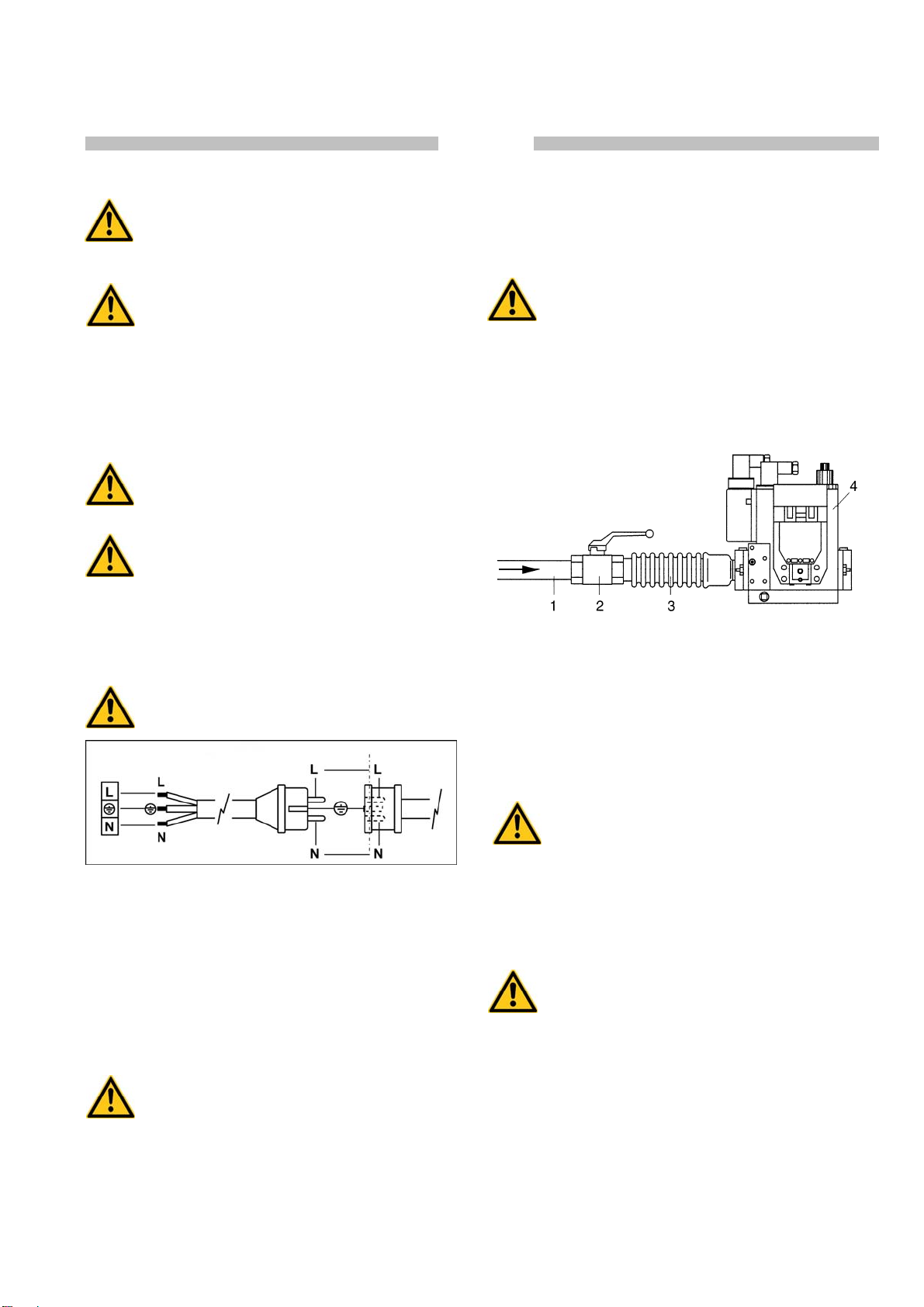
vorgeschriebenen Gasversorgungsdrücke betrieben werden. In Tab.
I sind für jedes EU-Land die verwendbaren Gase und die
Druckwerte, die entsprechende Klasse (Angabe der beiden
vorausgegangenen Informationen, und zwar Gassorte und
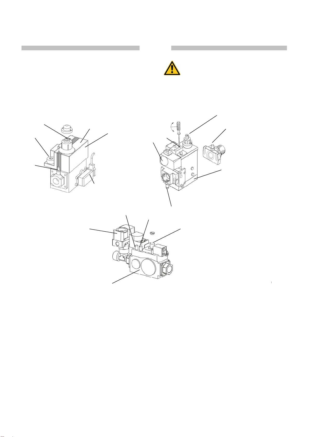
Versorgungsdruck), die Einstellung der Gasventileinheit und die
Voreinstellung des Düsenrings (3) angegeben.
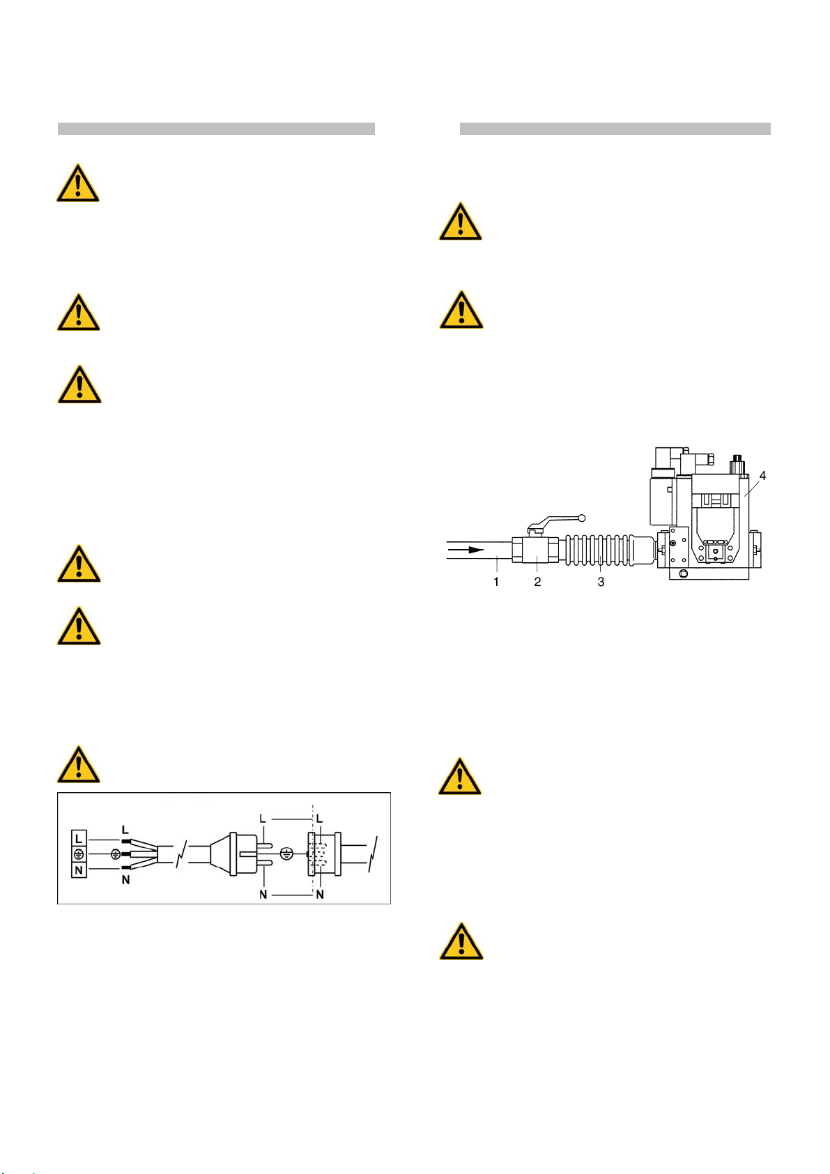
Der Warmlufterzeuger ist für eine Betriebsklasse aus Tab. I
voreingestellt. Diese Betriebsklasse wird vom Klebeetikett auf der
Gasventileinheit (4) angegeben.
Für die Umstellung auf eine andere Klasse und folglich auf eine
andere Gassorte sind spezifische Maßnahmen erforderlich, die im
Abschnitt „UMSTELLUNG AUF EINE ANDERE GASSORTE“
angegeben sind.
Die Warmlufterzeuger arbeiten mit direkter Verbrennung. Die Luft
wird unter Ausnutzung der während der Verbrennung erzeugten
Wärmeenergie erhitzt und anschließend, gemeinsam mit den
Verbrennungsgasen, in den zu beheizenden Raum geleitet. Der
Raum muss stets belüftet sein, um einen ausreichenden
Luftaustausch zu gewährleisten.
Verschiedene Sicherheitsvorrichtungen (elektronische
Kontrollvorrichtung, Sicherheitsthermostat LI, Luftpressostat und
Gaspressostat) sprechen bei schweren Betriebsstörungen an.
Die elektronische Kontrollvorrichtung des Brenners greift ein, wenn
die Flamme unregelmäßig ist oder erlischt oder die
Versorgungsspannung zu niedrig ist (T < 195 V). Der
Sicherheitsthermostat LI spricht an, wenn die
Brennkammertemperatur den Sicherheitsgrenzwert überschreitet.
Der Luft- und der Gaspressostat sprechen jeweils an, wenn die
Luftfördermenge bzw. der Gasversorgungsdruck zu niedrig ist.
In den genannten Fällen wird der Betrieb des Warmlufterzeugers
ausgesetzt und es schaltet sich die Lampe der Reset-Taste (8) ein
(außer bei zu niedrigem Gasdruck).
Der Betrieb wird im Fall des niedrigen Gasdrucks oder der
niedrigen Versorgungsspannung wieder aufgenommen, wenn die
erforderliche Versorgung wiederhergestellt ist.
In allen anderen Fällen kann der Betrieb erst wieder
aufgenommen werden, nachdem die Reset-Taste (8) oder (4)
gedrückt wurde, siehe Abschnitt „STÖRUNGEN, URSACHEN UND
ABHILFEN”.
Vor erneuter Ingangsetzung des Warmlufterzeugers ist stets die
Ursache für die Auslösung der Sicherheitsvorrichtung zu suchen und
zu beseitigen (vgl. „STÖRUNGEN, URSACHEN UND ABHILFEN“).
Für die Warmlufterzeuger ist das folgende Zubehör erhältlich:
a) Programmieruhr oder Raumthermostat oder eine anderweitige
elektromechanische Vorrichtung für die automatische Start- und
Stoppregelung
b) Set für die Fernbedienung über einen PC
c) Set für die Fernbedienung über ein externes Bedienpaneel
(Entfernung max. 5 m), empfehlenswert bei
behindertem/begrenztem Zugang zur Bedienblende infolge von
Deckenmontage oder beengten Platzverhältnissen
d) Set für die Anlaufverzögerung des Warmlufterzeugers,
empfehlenswert bei Mehrfachinstallationen zur Vermeidung der
Netzüberlastung
e) Set für den Kondensatschutz, unerlässlich in Räumen mit
hohem Feuchtigkeitsgehalt (Treibhäuser, Zuchtbetriebe etc.) zur
Vermeidung von Startausfällen.
ALLGEMEINE HINWEISE
Die Installation, die Einstellung und die Benutzung des
Warmlufterzeugers müssen den geltenden nationalen und örtlichen
Vorschriften und Gesetzen in Hinsicht auf den Gebrauch des
Gerätes entsprechen.
Der Warmlufterzeuger kann, unter Verwendung von Seilen bzw.
Ketten entsprechender Größe und Länge, die an den 4
Aufhängehaken zu befestigen sind, in Hängemontage an der Decke
angebracht werden.
Achtung
Sicherstellen, dass die Seile bzw. Ketten einen
maximalen Winkel von 5° gegen die Deckensenkrechte
bilden.
Der Mindestabstand von Wänden, Fußboden bzw. Decke soll
mindestens 1 m und der Bodenabstand soll mindestens 500 mm
betragen.
Der Mindestabstand von Gegenständen, Personen bzw. Tieren
am Austritt der aufbereiteten Luft soll mindestens 1,5 m betragen. Es
ist eine vorherige Prüfung erforderlich, welche die Verträglichkeit der
maximalen Temperatur ermittelt. Sie entspricht der Raumtemperatur
+ ∆T @ 1,5 m (siehe Klebeetikett am Warmlufterzeuger).
Es ist Folgendes sicherzustellen:
• Die Anweisungen der vorliegenden Anleitung sind streng zu
beachten;
• Der Warmlufterzeuger darf nicht in feuer- oder
explosionsgefährdeten Bereichen aufgestellt werden;
• In Gerätenähe dürfen keine feuergefährlichen Materialien
aufbewahrt werden (Abstand mindestens 3 m);
• Etwaige Wände, Decken und Fußböden aus entflammbarem
Material dürfen sich nicht zu stark erhitzen;
• Es sind die notwendigen Brandschutzmaßnahmen zu ergreifen;
• Die Belüftung des Aufstellungsraumes des Warmlufterzeugers
muss stets gewährleistet sein und dem Bedarf des Brenners
entsprechen: insbesondere sind die Grenzwerte für die
Luftqualität in dem zu beheizenden Raum gemäß der
nationalen oder lokalen Vorschriften oder, in Ermangelung
dieser, gemäß EN 12669:2003 zu beachten.
• Die Luftansaug- bzw. Luftförderkanäle dürfen nicht verdeckt
oder verstellt werden z.B. durch abgelegte Planen oder
Abdeckungen auf dem Gerät, Wände oder Gegenstände;
• Der Warmlufterzeuger soll in der Nähe einer Schaltanlage
aufgestellt werden, deren Stromwerte den deklarierten
Anschlusswerten entsprechen;
• Für das Gerät soll ein fester Aufstellungsplatz vorgesehen sein;
• Das Gerät soll während des Betriebs regelmäßig überwacht und
vor der Inbetriebsetzung kontrolliert werden;
• Bei Beginn jedes Gebrauchs ist vor Anschluss des Netzsteckers
zu überprüfen, dass der Ventilator ungehindert dreht;
• Nach dem Betrieb müssen stets der Trennschalter abgeschaltet
und der Gasabsperrhahn geschlossen werden.