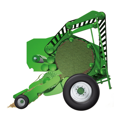
Krone Comprima CF 155 XC User manual

Original operating instructions
Round baler
Comprima CF 155 XC
Comprima CV 150 XC
Comprima CV 210 XC
(from serial no.: 911 106)
Order no.: 150 000 046 11 en
13.01.2015

Foreword
2
Pos: 1 /BA/Konfor mitätserklärungen/ Rundballenpressen/Co mprima CF/CV XC @ 199\mod_1384 866461792_78.doc x @ 1674414 @ @ 1
CV0
EC Declaration of Conformity
We Maschinenfabrik Bernard Krone GmbH
Heinrich-Krone-Str. 10, D-48480 Spelle
hereby declare as manufacturer of the product named below, on our sole responsibility,
that the
Machine: Krone Round Baler
Type / types: Comprima CF 155 XC
Comprima CV 150 XC
Comprima CV 210 XC
to which this declaration refers is in compliance with the relevant provisions of
EG-directive 2006/42/EG (machines) and EG directive 2004/108/EG (EMV).
The signing Managing Director is authorised to compile the technical documents.
Spelle, 01.10.2013
Dr.-Ing. Josef Horstmann
(Managing Director, Design and Development)
Year of manufacture: Machine No.:
Pos:2 /LayoutModule /---------------Seitenumbruch---------------- @ 0\mod_1196175311226_0.doc x@ 4165 @ @ 1

Foreword
3
Pos: 3.1 /Überschri ften/Überschri ften 1/U-Z/Vorwort @ 0\mod_ 1195627720123_78.doc x @ 982 @ 11 @ 1
1 Foreword
Pos: 3.2 /BA/Vor wort/Rundballenpressen/ Verehrter Kunde Rund ballenpresse @ 27\mod_12 46526159413_78.doc x @ 267781 @ @ 1
Dear Customer!
By purchasing the round baler, you have acquired a quality product from KRONE.
We are grateful for the confidence you have invested in us in buying this machine.
It is important to read the operating instructions very carefully before you start operating the
machine to allow you to use the round baler to its full capacity.
The contents of this manual are laid out in such a way that you should be able to perform any
task by following the instructions step by step. It contains extensive notes and information about
maintenance, how to use the machine safely, secure working methods, special precautionary
measures and available accessories. This information and these instructions are essential,
important and useful for the operational safety, reliability and durability of the round baler.
Pos: 3.3 /BA/Vor wort/Rundballenpressen/ Weiterer Verlauf Rundballenpresse @ 27\mod_1 246526537241_78.doc x@ 2678 06 @ @ 1
Note
In the operating instructions which follow, the round baler will also be referred to as the
"machine".
Pos: 3.4 /BA/Vor wort/Beachten Sie für Maschi ne @ 0\mod_1195626904076_7 8.docx @ 944 @ @ 1
Please note:
The operating instructions are part of your machine.
Only operate this machine after you have been trained to do so and according to these
instructions.
It is essential to observe the safety instructions!
It is also necessary to observe the relevant accident prevention regulations and other generally
recognised regulations concerning safety, occupational health and road traffic.
All information, illustrations and technical data in these operating instructions correspond to the
latest state at the time of publication.
We reserve the right to make design changes at any time and without notification of reasons.
Should you for any reason not be able to use these operating instructions either wholly or
partially, you can receive a replacement set of operating instructions for your machine by
quoting the number supplied overleaf.
We hope that you will be satisfied with your KRONE machine.
Maschinenfabrik Bernard Krone GmbH
Spelle
Pos:4 /LayoutModule /---------------Seitenumbruch---------------- @ 0\mod_1196175311226_0.doc x@ 4165 @ @ 1

Table of Contents
4
Pos: 5 /Überschrif ten/Überschrif ten1/ F-J/Inhaltsverzeic hnis @ 31\mod_12519699 52727_78.docx @ 302165 @ 11 @ 1
2 Table of Contents
Pos: 6 /BA/Inhaltsver zeichnis Sprachenne utral @ 10\mod_1221574899 104_0.docx @ 135495 @ @ 1
1Foreword.................................................................................................................................................3
2Table of Contents...................................................................................................................................4
3To this Document.................................................................................................................................11
3.1Validity..............................................................................................................................................11
3.2Target group of this document.........................................................................................................11
3.3How to use this document................................................................................................................11
3.4Identifying Symbols in the Operating Instructions............................................................................12
3.5Identification of the hazard warnings................................................................................................12
4Safety.....................................................................................................................................................13
4.1Purpose of Use.................................................................................................................................13
4.2Intended use.....................................................................................................................................13
4.3Basic safety instructions...................................................................................................................14
4.3.1Importance of the operating instructions...................................................................................14
4.3.2Personnel qualification..............................................................................................................14
4.3.3Children in danger.....................................................................................................................15
4.3.4Connect the machine to the tractor...........................................................................................15
4.3.5Structural changes to the machine ...........................................................................................15
4.3.6Additional equipment and spare parts ......................................................................................15
4.3.7Workstations and passengers...................................................................................................15
4.3.8Operational safety: Technically perfect condition.....................................................................16
4.3.9Danger zones............................................................................................................................17
4.3.10Keeping safety devices functional.............................................................................................19
4.3.11Personal protective equipment .................................................................................................19
4.3.12Safety signs on the machine.....................................................................................................20
4.3.13Traffic safety..............................................................................................................................20
4.3.14Parking the machine safely.......................................................................................................21
4.3.15Consumables............................................................................................................................21
4.3.16Dangers associated with the operational environment.............................................................21
4.3.17Sources of danger on the machine...........................................................................................22
4.3.18Dangers associated with certain activities: Climbing up and down..........................................23
4.3.19Dangers associated with certain activities: Work on the machine............................................23
4.3.20Dangers associated with certain activities: Working on wheels and tyres................................24
4.3.21Behaviour in hazardous situations and when accidents occur.................................................24
4.4Safety routines .................................................................................................................................25
4.4.1Stopping and securing the machine..........................................................................................25
4.4.2Supporting lifted machine and machine parts securely............................................................25
4.4.3Coupling the machine safely.....................................................................................................26
4.4.4Uncoupling the machine safely.................................................................................................26
4.4.5Preparing the machine for repair, maintenance and adjustment work.....................................27
4.4.6Starting the machine safely.......................................................................................................27
4.5Position of the Adhesive Safety Stickers on the Machine................................................................28
4.6Introduction.......................................................................................................................................28
4.6.1Re-Ordering the Adhesive Safety and Information Labels .......................................................42
4.6.2Affixing the Adhesive Safety and Information Labels ...............................................................42
4.6.3Contact......................................................................................................................................42
4.7Safety Equipment.............................................................................................................................43

Table of Contents
5
4.7.1Parking brake............................................................................................................................44
4.7.2Attaching the safety cable.........................................................................................................45
4.7.3Wheel chocks............................................................................................................................45
4.7.4Secure the machine against the possibility of rolling back. ......................................................46
4.7.5Stop Points................................................................................................................................46
4.7.6Lifting Eyes................................................................................................................................46
4.7.7Raise.........................................................................................................................................46
4.7.8Parking Support ........................................................................................................................47
4.7.9Lowering the Parking Support...................................................................................................47
4.7.10Shut-off valve for tailgate..........................................................................................................48
4.7.11Step for working on the linkage.................................................................................................49
4.7.12Rollers on the Wrapping Table .................................................................................................50
4.7.13Platform on the Wrapping Table...............................................................................................51
4.8Identification Plate............................................................................................................................52
4.9Information Required for Questions and Orders..............................................................................52
4.10Technical data..................................................................................................................................53
5Commissioning.....................................................................................................................................56
5.1Before initial start-up ........................................................................................................................57
5.2Removing the transport holding down tensioning device.................................................................60
5.3Changing the Drawbar Height and Adjusting the Hitch....................................................................62
5.4PTO shaft.........................................................................................................................................65
5.4.1Length adjustment.....................................................................................................................65
5.4.2Mounting the PTO shaft on the machine side...........................................................................66
5.5Hose holder assembly......................................................................................................................69
6Start-up..................................................................................................................................................70
6.1Mounting onto the Tractor................................................................................................................71
6.2Hydraulics.........................................................................................................................................72
6.2.1Special Safety Instructions........................................................................................................72
6.2.2Connecting the hydraulic lines..................................................................................................73
6.3Hydraulic brake (Export) ..................................................................................................................76
6.4Install the PTO shaft.........................................................................................................................77
6.5Compressed Air Connections for the Compressed Air Brake..........................................................79
6.6Electrical connections ......................................................................................................................80
6.6.1Connecting the terminal (on tractors without ISOBUS system)................................................81
6.6.2Connecting the Terminal (on tractors with integrated ISOBUS system)...................................82
6.7Using the safety chain......................................................................................................................83
6.8Net Brake .........................................................................................................................................85
6.9Running-in Period.............................................................................................................................85
6.9.1.1Cam-type Clutch Engaging................................................................................................85
6.10Wrapping table.................................................................................................................................86
6.11Using the bale cloth..........................................................................................................................87
6.12Start-up Bale Turner.........................................................................................................................88
6.13Mounting the Stop / Holding Tube....................................................................................................89
6.14Positioning the Bale Turner..............................................................................................................90
6.15Moving the Bale Turner into Working Position.................................................................................91
6.15.1Adjusting the Baffle Plate..........................................................................................................91
6.16Adjusting the parking jack ................................................................................................................92
6.17Moving the Bale Turner into Transport Position...............................................................................93
6.18Mounting the bale cloth on the bale turner.......................................................................................94

Table of Contents
6
6.19Removing the bale turner.................................................................................................................94
7Driving and Transport..........................................................................................................................95
7.1Preparations for road travel..............................................................................................................96
7.1.1Lifting the Pick-up......................................................................................................................96
7.1.2Checking Parking Support ........................................................................................................97
7.1.3Checking the lighting system....................................................................................................97
7.1.4Attaching the bale cloth.............................................................................................................98
7.2Parking.............................................................................................................................................99
7.2.1Securing the Machine Against the Possibility of Rolling Back..................................................99
7.2.2Lowering the Parking Support.................................................................................................100
7.2.3Disconnecting the PTO shaft from the tractor.........................................................................100
7.2.4Disconnecting the Supply Lines..............................................................................................101
8KRONE ISOBUS Terminal..................................................................................................................102
8.1Installing the terminal into cabin.....................................................................................................103
8.2ISOBUS Short Cut Button..............................................................................................................104
8.2.1Connecting the Multi-Function Lever to the CCI Terminal (on Tractors with an Integrated
ISOBUS System).....................................................................................................................................106
8.2.2Connecting the Multi-Function Lever to the CCI Terminal (on tractors without ISOBUS system)107
8.2.3Switching the terminal on / off when the machine is not connected.......................................108
8.2.4Switching the terminal on / off when the machine is connected.............................................109
8.3Basic Screen..................................................................................................................................111
8.3.1Adjustment of bale firmness (display for Comprima CF 155 XC)...........................................118
8.3.2Adjustment of target bale diameter (display for Comprima CV150XC)..................................119
8.3.3Adjusting the Target Bale Diameter (Display for Comprima CV 210 XC)...............................119
8.4Messages.......................................................................................................................................120
8.5Menu level......................................................................................................................................122
8.5.1Short overview ........................................................................................................................122
8.5.2Calling up the menu level........................................................................................................125
8.6Main menu 1 Settings ....................................................................................................................126
8.7Menu 1-2 Adjustment baler............................................................................................................127
8.7.1Menu 1-2-2 Bale diameter (Only for Comprima CF155XC)....................................................128
8.7.2Menu 1-2-3 Number net winds................................................................................................129
8.7.3Menu 1-2-4 Sensitivity of the Direction Display (Only Comprima CF155)..............................130
8.7.4Menu 1-2-5 Pre-signalling.......................................................................................................131
8.7.5Menu 1-2-6 Filling Correction..................................................................................................132
8.7.6Menu 1-2-9 Tying start delay..................................................................................................133
8.8Menu 1-3 Adjustment wrapper.......................................................................................................134
8.8.1Menu 1-3-1 Number of layers.................................................................................................135
8.8.2Menu 1-3-2 Number slide wrappings......................................................................................136
8.8.3Menu 1-3-3 Type of operation wrapper...................................................................................137
8.8.4Menu 1-3-4 Type of operation swivel table.............................................................................138
8.8.5Menu 1-3-5 Sheet width..........................................................................................................139
8.8.6Menu 1-3-6 Torn sheet control................................................................................................140
8.9Main menu 2 Counters...................................................................................................................142
8.9.1Menu 2-1 Customer counter...................................................................................................143
8.9.2Menu 2-2 Total bale counter...................................................................................................145
8.10Main menu 3 Manual operation......................................................................................................146
8.10.1Menu 3-1 „Manual operation baler" ........................................................................................147
8.10.2Status messages.....................................................................................................................148

Table of Contents
7
8.10.3Move manually to tying position..............................................................................................150
8.10.4Activating the wrapping table manually (only for Comprima CV150XC) ................................150
8.10.5Drive lifter manually upward/ downward (Comprima CF155XC/CV210XC)...........................151
8.10.6Opening/closing the bale chamber .........................................................................................151
8.10.7Move swivel table by hand......................................................................................................152
8.11Menu 3-2 Manual operation wrapper.............................................................................................152
8.11.1Opening/closing the holding arms...........................................................................................153
8.11.2Switching on/off wrapping arm................................................................................................154
8.11.3Move the wrapping arm to zero position.................................................................................154
8.12Menu 3-2 „Manual Operation Wrapping Arm" CV 210...................................................................155
8.12.1Move the Height of the Wrapping Arms..................................................................................156
8.12.2Drive Height Wrapping Arm Into Parking Position..................................................................157
8.12.3Error messages Manual operation..........................................................................................159
8.13Main menu 4 Service .....................................................................................................................160
8.13.1Menu 4-2 Manual sensor test .................................................................................................161
8.13.2Actuator test............................................................................................................................171
8.13.3Menu 4-4 Manual actuator test...............................................................................................171
8.13.4Menu 4-8 Diagnostics .............................................................................................................176
8.13.5Menu 4-9 Manual operation without confirmation prompt.......................................................177
8.14Main Menu 5 Information ...............................................................................................................179
8.15Main Menu 6 Technician................................................................................................................179
8.16Main Menu 7 ISOBUS....................................................................................................................180
8.16.1Menu 7-1 Virtual Terminal (VT)...............................................................................................181
8.16.2Menu 7-1-1 Select day/night display lighting..........................................................................182
8.16.3Menu 7-1-3 „Softkeys ISO Terminal“......................................................................................183
8.16.4Menu 7-1-4 Switch to different terminal..................................................................................185
8.17Menu 7-4 ISOBUS Diagnostics......................................................................................................186
8.17.1Menu 7-4-2 Diagnostics Auxiliary Functions (AUX)................................................................187
8.18Messages.......................................................................................................................................188
8.18.1Query message for bale chamber...........................................................................................188
8.18.2Query message manual operation.........................................................................................188
8.18.3Prompt message Repeat wrapping.........................................................................................189
8.18.4Alarm messages .....................................................................................................................190
8.18.5Acoustic warnings...................................................................................................................190
8.18.6Note and messages................................................................................................................191
8.18.7Prompts...................................................................................................................................193
8.18.8Physical messages .................................................................................................................194
8.18.9General Messages..................................................................................................................196
9ISOBUS operation ..............................................................................................................................197
9.1Mounting ISOBUS Terminal...........................................................................................................198
9.1.1Connection Terminal to Tractor ..............................................................................................198
9.1.2Connection Tractor to Machine...............................................................................................198
9.2Differing functions to KRONE ISOBUS terminal CCI.....................................................................199
9.3ISOBUS „Auxiliary“-function (AUX)................................................................................................200
9.3.1Example of joystick assignment for Fendt (default setting) ....................................................201
9.3.2Recommended settings for a WTK multi-function lever (default setting)................................202
10Operation of the Hydraulic Zero Setting of Blades (Optional).......................................................203
10.1KRONE ISOBUS Terminal.............................................................................................................204
10.1.1Basic screen in case of a connected zero setting of blades (option)......................................204

Table of Contents
8
10.1.1.1Sensor test / actuator test................................................................................................206
10.1.1.2Alarm messages for blade comfort selection...................................................................207
10.2Hydraulic System Circuit Diagrams................................................................................................208
11Operation.............................................................................................................................................209
11.1Adjustments Before Starting Work.................................................................................................210
11.2Travelling speed.............................................................................................................................212
11.3Filling the bale chamber.................................................................................................................213
11.3.1Reducing the Pressure on the Side Walls of the Bale Chamber............................................215
11.3.1.1Assembly of Additional Tappet Strips on the Starter Roller.............................................215
11.3.1.2Assembly of Additional Ejector Plates in the Tailgate .....................................................216
11.4Tying and depositing bales ............................................................................................................219
11.5Before Baling..................................................................................................................................219
11.5.1Detaching the bale cloth .........................................................................................................219
11.5.2Tensioning the floor conveyor.................................................................................................220
11.6After Baling.....................................................................................................................................221
11.6.1Releasing tension on the floor conveyor.................................................................................221
11.7Overload protection........................................................................................................................222
11.7.1Drive Chain for Pick-up with Cam-type Clutch........................................................................222
11.8Pick-up ...........................................................................................................................................223
11.8.1Default Setting (Working Height Setting)................................................................................223
11.8.2Bearing Pressure Relief of the Pick-up...................................................................................224
11.9Roller crop guide............................................................................................................................225
11.10Adjusting the baffle plate................................................................................................................226
11.11Cutting system................................................................................................................................227
11.11.1General Aspects......................................................................................................................227
11.11.2Cutting length..........................................................................................................................228
11.11.3Zero position of the cutter .......................................................................................................231
11.12Setting the Bale Diameter..............................................................................................................235
11.13Setting Baling Pressure..................................................................................................................236
11.14Net Wrapping .................................................................................................................................239
11.14.1Net wrapping parts..................................................................................................................239
11.14.2Function of the Net Tying........................................................................................................239
11.15Inserting Net Roll............................................................................................................................240
11.15.1Insert Net.................................................................................................................................241
11.15.2Setting of the Feed Position....................................................................................................243
11.15.3Setting of the Tying Position...................................................................................................244
11.15.4Selecting the Number of Net Winds........................................................................................244
11.15.5Setting Cut-off Position...........................................................................................................245
11.16Adjusting Soft Core ........................................................................................................................246
11.17Blockage Due to Jammed Crop.....................................................................................................249
11.18Bale Wrapper .................................................................................................................................251
11.18.1Special Safety Instructions......................................................................................................251
11.18.2Components Bale Wrapper.....................................................................................................252
11.18.3Function Bale Wrapper ...........................................................................................................255
11.18.4Store Bale ...............................................................................................................................256
11.18.5Inserting Sheet........................................................................................................................257
11.18.6Adjusting the Sheet Brake ......................................................................................................262
11.18.7Setting the Pre-stretch of the Foil ...........................................................................................263
11.18.8Adjusting the Gearbox on the Swivel table.............................................................................264
Table of Contents
9
11.19Removing the Crop Blockages in the Crop Collection Area ..........................................................265
11.19.1Crop blockage under the cutting rotor.....................................................................................266
11.19.2Crop blockage at pick-up ........................................................................................................268
12Settings ...............................................................................................................................................269
12.1Setting the Net Brake.....................................................................................................................269
12.1.1Releasing the Net Brake.........................................................................................................270
12.2Central chain lubrication system....................................................................................................271
13Maintenance........................................................................................................................................275
13.1Spare Parts ....................................................................................................................................275
13.2Maintenance table..........................................................................................................................276
13.3Setting of the Scraper Rail to the Upper Spiral Roller....................................................................277
13.4Position of the Sensors ..................................................................................................................279
13.4.1Adjusting the Sensors.............................................................................................................283
13.4.1.1Namur sensor d = 12 mm................................................................................................283
13.4.1.2Namur Sensor d = 30 mm................................................................................................283
13.4.1.3Sensor Position Cutter base (B8)....................................................................................284
13.4.2Checking and Setting Axial Play of the Net Brake..................................................................285
13.5Tightening torques..........................................................................................................................286
13.6Tightening torques (countersunk screws)......................................................................................287
13.7Tandem Axle..................................................................................................................................288
13.7.1Setting of the Brakes with Hydraulic Linkage Setter...............................................................290
13.8Tyres ..............................................................................................................................................291
13.8.1Checking and maintaining tyres..............................................................................................292
13.8.2Tyre air pressure.....................................................................................................................293
13.9Drawbar..........................................................................................................................................294
13.9.1Hitches on the Drawbar ..........................................................................................................294
13.10Oil Level Check and Oil Change on the Gearboxes......................................................................295
13.10.1Oil Level Check and Oil Change Intervals (Gearboxes).........................................................295
13.10.2Filling Quantities and Lubrication Designations for Gearboxes..............................................295
13.10.3Main drive................................................................................................................................296
13.10.4Slip-on Gear............................................................................................................................297
13.11Screw connections at the front and rear of the floor conveyors.....................................................298
13.12Novo Grip belt on the floor conveyor..............................................................................................299
13.13Checking the Safety Rollers of Single Blade Locking Device........................................................300
13.14Checks and maintenance on rear floor conveyor ..........................................................................301
13.14.1Adjusting the deflection roller..................................................................................................302
13.15Wrapping table chain......................................................................................................................303
13.16Drive chains....................................................................................................................................304
13.16.1Tensioning the Drive Chains...................................................................................................304
13.16.1.1Front Floor Conveyor Drive .............................................................................................304
13.16.1.2Rear Floor Conveyor Drive..............................................................................................305
13.16.1.3Pick-up.............................................................................................................................306
13.16.1.4Conveyor Auger Drive......................................................................................................308
13.16.1.5Roller Drive......................................................................................................................308
13.17Wrapping Arm Bearing...................................................................................................................309
13.18Hydraulics.......................................................................................................................................311
13.18.1Shut-off valve for tailgate........................................................................................................312
13.18.2On-board Hydraulic System....................................................................................................313
13.18.3Hydraulic Tank........................................................................................................................315

Table of Contents
10
13.18.4Changing the filter on the hydraulic tank ................................................................................318
13.18.5Replacing the Hydraulic Oil Filter............................................................................................321
13.18.6Electromagnetic Valves ..........................................................................................................323
13.19Grinding blades..............................................................................................................................324
13.20Maintenance – brake system (special equipment).........................................................................325
13.20.1Coupling heads (non-interchangeable)...................................................................................326
13.20.2Air filter for pipelines................................................................................................................327
13.20.3Compressed-air reservoir .......................................................................................................328
14Maintenance – lubrication.................................................................................................................329
14.1Lubricants.......................................................................................................................................330
14.2General aspects.............................................................................................................................330
14.3Lubricating the PTO shaft ..............................................................................................................330
14.4WALTERSCHEID cam-type clutch K64/12 to K64/24, EK 64/22 to EK64/24................................331
14.5Lubrication points...........................................................................................................................333
15Placing in Storage..............................................................................................................................337
15.1At the End of the Harvest Season..................................................................................................337
15.2Before the Start of the New Season...............................................................................................338
15.2.1Maintenance work before the beginning of the new season ..................................................339
15.2.2Venting the overload coupling on the PTO shaft....................................................................340
16Malfunctions - Causes and Remedies..............................................................................................341
16.1General malfunctions .....................................................................................................................342
16.2Malfunctions on the central chain lubrication system.....................................................................345
16.3Malfunctions on the Wrapping Mechanism....................................................................................346
16.4Error Messages of KRONE Operation Terminal............................................................................346
17Disposal of the machine....................................................................................................................347
17.1Disposal of the machine.................................................................................................................347
18Appendix.............................................................................................................................................348
18.1Hydraulic System Circuit Diagrams................................................................................................348
18.2Electrical circuit diagram ................................................................................................................354
19Index....................................................................................................................................................355
Pos:7 /LayoutModule /---------------Seitenumbruch---------------- @ 0\mod_1196175311226_0.doc x@ 4165 @ @ 1

To this Document
11
Pos: 8 /Überschrif ten/Überschrif ten1/ U-Z/Zu diesem Dokument @ 107\ mod_1334231929021_78. docx @ 965257 @ 11 @ 1
3 To this Document
Pos: 9 /BA/Einleitun g/Gültigkeit/Rundb allenpressen/ Gültigkeit Comprima F/ V X-treme @ 307\mod_14163814 69758_78.docx @ 2382895 @2 @ 1
3.1 Validity
These operating instructions are valid for round balers of types:
Comprima F 155 XC X-treme Comprima V 150 XC X-treme
Pos: 10 /Überschrif ten/Überschrif ten2/ U-Z/Zielgruppe die ses Dokuments @ 187\mod_1380 113123454_78.doc x@ 160 9723 @ 22 @ 1
3.2 Target group of this document
Pos: 11 /BA/Zu diesem Doku ment/Zielgruppe @ 188\ mod_1380114987653_78. docx @ 1610148 @ @ 1
This document is intended for the farmer and for other users who have no agricultural training
but who have been instructed in the use of the machine.
Pos: 12 /Überschrif ten/Überschrif ten2/ P-T/So benutzen Sie diese s Dokument @ 188\mod_138 0548350021_78.doc x@ 16143 65 @ 22 @ 1
3.3 How to use this document
Pos: 13 /BA/Zu diesem Doku ment/So benutzen Sie diese An leitung @ 188\mod_13 80548527264_78.doc x@ 1614 394 @ @ 1
Table of contents/headers:
The table of contents, as well as the headers in these instructions, are used for quick navigation
in the chapters.
Index:
You can use the index to find specific information on the required subject via keywords which
are in alphabetical order. The index is on the last page of these instructions.
Cross-references:
Cross-references to another place in the operating instructions or to another document are in
the text and specify the chapter and subchapter or section. The name of the subchapter or
section is in quotation marks.
Example:
Check that all screws on the machine are tight, see chapter Maintenance, "Tightening torques
for hexagonal head screws".
The subchapter or the section can be found via an entry in the table of contents and in the
index.
Pos: 15 /BA/Zu diesem Doku ment/Richtungs- und Ori entierungsangaben @ 188\ mod_1380609039179_ 78.docx @ 1615134 @ @ 1
Directional information in these operating instructions, such as front, rear, right and left, applies
in the direction of travel of the machine.
Orientation information concerning a diagram of a machine detail refers to the diagram itself and
is not relative to the direction of travel.
Pos:16 /LayoutModule /---------------Seitenumbruch----------------@ 0\mod_1196175311226_0. docx @ 4165 @ @ 1

To this Document
12
Pos: 17 /BA/Sic herheit/6. Überarbeitete W arnhinweise/Kennzei chnung von Hinweisen i n der Betriebsanleitung Ei nführungstext (2012- 07-27 09:59:06) @ 0\mod_1195 637804826_78.doc x@ 109 8 @ 22 @ 1
3.4 Identifying Symbols in the Operating Instructions
The safety instructions contained in this manual which could result in personal injury if not
followed are identified by the general danger sign:
Pos: 18 /BA/Sic herheit/6. Überarbeitete W arnhinweise/Kennzei chnung der Gefahrenhi nweise (2012-07-26 15: 10:30) @ 28\mod_12502443 70070_78.docx @ 274714 @ 22@ 1
3.5 Identification of the hazard warnings
Danger!
DANGER! - Type and source of the hazard!
Effect: Danger to life or serious injuries.
• Measures for hazard prevention
Warning !
WARNING! - Type and source of the hazard!
Effect: Injuries, serious material damage.
• Measures for hazard prevention
Caution!
CAUTION! - Type and source of the hazard!
Effect: Property damage
• Measures for risk prevention.
Pos: 19 /BA/Sic herheit/6. Überarbeitete W arnhinweise/Allge meine Funktionshinwei se (2012-07-26 15:24:39) @ 0\mod_1196869714452_ 78.docx @ 15185 @ @ 1
General function instructions are indicated as follows:
Note!
Note - Type and source of the note
Effect: Economic advantage of the machine
• Actions to be taken
Instructions which are attached to the machine need to be followed and kept fully legible.
Pos:20 /LayoutModule /---------------Seitenumbruch----------------@ 0\mod_1196175311226_0. docx @ 4165 @ @ 1

Safety
13
Pos: 21 /Überschrif ten/Überschrif ten1/ P-T/Sicherheit @ 0\ mod_1195566748646_78. docx @ 635 @ 11 @ 1
4 Safety
Pos: 22 /Überschrif ten/Überschrif ten2/ U-Z/Verwendungsz weck @ 1\mod_1201707246738_ 78.docx @ 54055 @ 22 @ 1
4.1 Purpose of Use
Pos: 23 /BA/Maschinen beschreibung/Maschi nenübersicht/ Rundballenpressen/Ver wendungszweck Compri ma CF155XC, CV150/210XC @ 199\mod_1384871208494_ 78.docx @ 1674872 @ @ 1
The round balers with integrated wrapping machine of type Comprima CF155 XC,
Comprima CV150/210 XC are pick-up balers with a variable bale chamber. These balers cut,
compact and wrap agricultural crop into round bales.
These bales can be wrapped with sheet immediately after the baling process. If necessary, it is
also possible to put them down without sheet wrapping.
Round balers are serially equipped with a net tying and a rotating chopping system.
Pos: 24 /BA/Maschinen beschreibung/Maschi nenübersicht/ Großpackenpressen/ Aufnahme und Pressung nic ht genannter Pressgü ter @ 17\mod_12361705631 05_78.docx @ 201591 @ @ 1
WARNING! – Intake and baling of pressing material not mentioned!
Effect: Damage to the machine
Collecting and baling materials that are not cited here is permitted only in agreement with the
manufacturer. The basic requirements in any case are swath form loading of the crops and
automatic intake by the Pick-up as it passes over them.
Pos: 25.1 /Überschri ften/Überschri ften 2/A-E/Bestimmungs gemäße Verwendung @ 103\mod_1 332169199326_78.d ocx @ 940071 @ 22 @ 1
Ver
4.2 Intended use
Pos: 25.2 /BA/Einlei tung/Bestimmungsge mäßer Gebrauch/Rundba llenpresse/Besti mmungsgemäßer Gebrauch Rundballenpresse @ 32\mod_12 53019678915_78.doc x @ 308291 @ @ 1
The round baler is built exclusively for customary use in agricultural work (intended use).
Pos: 25.3 /BA/Einlei tung/Bestimmungsge mäßer Gebrauch/Nicht b estimmungsgemäß @ 103\ mod_1332171672294_78. docx @ 940272 @ @ 1
Unauthorised modifications to the machine may have a negative effect on the machine
characteristics or safe and reliable use of the machine or may interfere with proper operation.
Unauthorised modifications shall therefore release the manufacturer of any liability for
consequential damage.
Pos:26 /LayoutModule /---------------Seitenumbruch----------------@ 0\mod_1196175311226_0. docx @ 4165 @ @ 1

Safety
14
Pos: 27.1 /Überschri ften/Überschri ften 2/F-J/Grundlegende Si cherheitshin weise@ 186\mod_1380009482364_ 78.docx @ 1606585 @ 22 @ 1
4.3 Basic safety instructions
Pos: 27.2 /BA/Sic herheit/1. Grundlegende Si cherheitshinweise/ Nichtbeachtung der SiHi und WaHi (Einführte xt Grundlegende SiHi) @ 175\ mod_1372834139379_78. docx @ 1504793 @ @ 1
Non-compliance with the safety instructions and warnings
Non-compliance with the safety instructions and warnings may result in injuries and damage to
the environment and property.
Pos: 27.3 /Überschri ften/Überschri ften 3/A-E/B/Bedeutung der Betriebsanleitung @ 186\ mod_1380011391583_7 8.docx @ 1606670 @ 33 @ 1
4.3.1 Importance of the operating instructions
Pos: 27.4 /BA/Sic herheit/1. Grundlegende Si cherheitshinweise/ Bedeutung der Betri ebsanleitung @ 175\mod_1 372834861914_78.d ocx @ 1504822 @ @ 1
The operating instructions are an important document and a part of the machine. They are
intended for the user and contain information relevant to safety.
Only the procedures indicated in the operating instructions are reliable. If the operating
instructions are not followed, people may be seriously injured or killed.
• Before using the machine for the first time, read and follow all the "Basic safety instructions"
in the chapter Safety.
• Before working, also read and observe the respective sections in the operating instructions.
• Retain the operating instructions and ensure that they are always available.
• Hand over the operating instructions to subsequent users.
Pos: 27.5 /Überschri ften/Überschri ften 3/P-T/Personalqua lifikation @ 187\mod _1380011550253_78.doc x @ 1606703 @ 33 @ 1
4.3.2 Personnel qualification
Pos: 27.6 /BA/Sic herheit/1. Grundlegende Si cherheitshinweise/ Personalqualif ikation @ 176\mod_13728 40611484_78.doc x@ 1505 639 @ @ 1
If the machine is not used properly, people may be seriously injured or killed. To avoid
accidents, each person who works with the machine must satisfy the following minimum
requirements:
– He is physically capable of controlling the machine.
– He can work safely with the machine in accordance with these operating instructions.
– He understands the method of operation of the machine within the scope of his work and
can identify and avoid the dangers associated with the work.
– He has read the operating instructions and can implement the information in the operating
instructions accordingly.
– He is familiar with driving vehicles safely.
– For road travel he has adequate knowledge of the highway code and has the stipulated
driving licence.
Pos:27.7 /LayoutModule/---------------Seitenumbruch----------------@ 0\mod_1196175311226_0.doc x@ 4165 @ @ 1

Safety
15
Pos: 27.8 /Überschri ften/Überschri ften 3/K-O/Kinder in Gefahr @187\ mod_1380011650765_78. docx @ 1606732 @ 33 @ 1
4.3.3 Children in danger
Pos: 27.9 /BA/Sic herheit/1. Grundlegende Si cherheitshinweise/ Kinder in Gefahr ( Anhängegerät, Anbaugerä t, Anhänger) @ 176\mod_13 72842540941_78.doc x@ 1505 758 @ @ 1
Children cannot assess danger and behave unpredictably.
As a result, children are especially at risk.
• Keep children away from the machine.
• Keep children away from consumables.
• Especially before starting up and moving the machine, ensure that there are no children in
the danger zone.
Pos: 27.10 /Übersc hriften/Überschri ften 3/K-O/Maschine an de n Traktor ankuppeln @ 279\ mod_1405347497196_78. docx @ 2150065 @ 33 @ 1
4.3.4 Connect the machine to the tractor
Pos: 27.11 /BA/Sic herheit/1. Grundlegend e Sicherheitshinweis e/Ankuppeln der Masc hine an den Traktor (Gerä teu. Anhänger) @ 279\mod_140 5409566743_78.doc x@ 215064 5 @ @ 1
If the tractor and the machine are not correctly connected, there is a risk of causing serious
accidents.
• When connecting front attachments or trailers, follow all operating instructions:
– The operating instructions for the tractor
– The operating instructions for the machine
– The operating instructions for the universal shaft
• Follow the coupling instructions, see chapter on starting up "Connect the machine to the
tractor".
• Note the modified driving behaviour of the combination.
Pos: 27.12 /Übersc hriften/Überschri ften 3/A-E/B/Baulic he Änderungen an der Maschine @ 187\mod_1380011874486_78. docx @ 1606786 @ 33 @ 1
4.3.5 Structural changes to the machine
Pos: 27.13 /BA/Sic herheit/1. Grundlegend e Sicherheitshinweis e/Bauliche Änderunge n an der Maschine @ 176\mod_13 72843690190_78. docx @ 1506085 @ @ 1
Structural changes and enhancements may impair the functionality and operational safety of the
machine. As a result, people may be seriously injured or killed.
• Have structural changes and enhancements performed by an authorised service centre
only.
Pos: 27.14 /Übersc hriften/Überschri ften 3/U-Z/Zusatzausr üstungen und Ersatz teile @ 187\mod_138001200 0801_78.docx @ 1606819 @ 33 @ 1
4.3.6 Additional equipment and spare parts
Pos: 27.15 /BA/Sic herheit/1. Grundlegend e Sicherheitshinweis e/Zusatzausrüstun gen und Ersatzteile @ 176\ mod_1372844184073_7 8.docx @ 1506194 @ @ 1
Additional equipment and spare parts, which do not comply with the requirements of the
manufacturer, may impair the operational safety of the machine and cause accidents.
• To ensure operational safety, use original or standard parts which comply with the
requirements of the manufacturer. If in doubt, have parts verified by the dealer or
manufacturer.
Pos: 27.16 /Übersc hriften/Überschri ften 3/A-E/A/Arbei tsplätze und mitfahrende Per sonen @ 187\mod_13800121 30656_78.docx @ 16068 49 @ 33 @ 1
4.3.7 Workstations and passengers
Pos: 27.17 /BA/Sic herheit/1. Grundlegend e Sicherheitshinweis e/Arbeitsplätz e - Kontrolle über die fahr ende Maschine @ 176\mod_13728 50001832_78.doc x@ 15064 13 @ @ 1
Control of the moving machine
The moving machine requires the driver to react quickly at any time. Otherwise, the machine
may move in an uncontrolled manner and seriously injure or kill people.
• Start the engine from the driver's seat only.
• Never leave the driver's seat while the machine is moving.
• Never climb in or out of the machine while it is moving.
Pos: 27.18 /BA/Sic herheit/1. Grundlegend e Sicherheitshinweis e/Arbeitsplätz e - Mitfahrende Personen ( Gerät und Anhänger) @ 176\ mod_1372850186689_78.doc x @ 1506442 @ @ 1
Passengers
Passengers may be seriously injured by the machine or fall off the machine and get run over.
Ejected objects may strike and injure passengers.
• Never let people ride on the machine.
Pos:27.19 /LayoutModule/---------------Seitenumbruch----------------@ 0\mod_1196175311226_0.docx @ 4165 @ @ 1

Safety
16
Pos: 27.20 /Übersc hriften/Überschri ften 3/A-E/B/Betri ebssicherheit: Techni sch einwandfreier Zustand @ 187\mod_1380012216128 _78.docx @ 1606877 @ 33 @ 1
4.3.8 Operational safety: Technically perfect condition
Pos: 27.21 /BA/Sic herheit/1. Grundlegend e Sicherheitshinweis e/Betriebssic herheit - Betrieb nur nac h ordnungsgemäßer Inbetri ebnahme @ 176\mod_137285 4464728_78.doc x@ 15065 30 @ @ 1
Operation only when the machine has been started up correctly
If the machine is not started up correctly according to these operating instructions, the
operational safety of the machine is not ensured. As a result, accidents may occur and people
may be seriously injured or killed.
• Do not use the machine unless it has been started up correctly, see chapter Start-up.
Pos: 27.22 /BA/Sic herheit/1. Grundlegend e Sicherheitshinweis e/Betriebssic herheit - Technisch einwandf reier Zustand der Masc hine @ 176\mod_1372854718 958_78.docx @ 1506559 @ @ 1
Technically perfect condition of the machine
Improper maintenance and adjustment may affect the operational safety of the machine and
cause accidents. As a result, people may be seriously injured or killed.
• Perform all maintenance and adjustment work according to the chapters Maintenance and
Adjustment.
• Before performing any maintenance or adjustment work, shut down and safeguard the
machine, see chapter Safety "Shutting down and safeguarding the machine".
Pos: 27.23 /BA/Sic herheit/1. Grundlegend e Sicherheitshinweis e/Betriebssic herheit - Gefahr durch Sc häden an der Maschine @ 176\mod_ 1372856430313_78.doc x@ 1506 618 @ @ 1
Danger resulting from damage to the machine
Damage to the machine may impair the operational safety of the machine and cause accidents.
As a result, people may be seriously injured or killed. The following parts of the machine are
particularly important for safety:
– Brakes
– Steering
– Safety devices
– Connecting devices
– Lighting
– Hydraulic system
– Tyres
– Universal shaft
If there are doubts about the operational safety of the machine, for example due to leaking
consumables, visible damage or an unexpected change to the driving behaviour:
• Shut down and safeguard the machine, see chapter Safety, "Shutting down and
safeguarding the machine".
• Immediately eliminate potential causes of damage, for example heavy soiling, or tighten
slack screws.
• Determine the cause of damage according to these operating instructions, see chapter
Malfunctions – Cause and remedy.
• If possible, repair the damage according to these operating instructions.
• In the case of damage which may affect operational safety and cannot be repaired
according to these operating instructions: Have damage repaired by a qualified service
centre.
Pos:27.24 /LayoutModule/---------------Seitenumbruch----------------@ 0\mod_1196175311226_0.docx @ 4165 @ @ 1

Safety
17
Pos: 27.25 /BA/Sic herheit/1. Grundlegend e Sicherheitshinweis e/Betriebssic herheit - Technische Grenz werte @ 176\mod_137285725 1111_78.docx @ 1506647 @ @ 1
Technical limit values
If the technical limit values of the machine are not observed, the machine may be damaged. As
a result, accidents may occur and people may be seriously injured or killed. Observance of the
following technical limit values is particularly important for safety:
– Permitted gross weight
– Maximum axle loads
– Maximum payloads
– Maximum trailer load
– Maximum bearing load
– Maximum transport height
– Maximum speed
• Observe limit values, see chapter Description of machine, "Technical data".
Pos: 27.26 /Übersc hriften/Überschri ften 3/F-J/Gefahrenber eiche @ 187\mod_138001 2427290_78.docx @ 16069 06 @ 33 @ 1
4.3.9 Danger zones
Pos: 27.27 /BA/Sic herheit/1. Grundlegend e Sicherheitshinweis e/Gefahrenbereic he rund um Anhängegerät, Anbaugerät o. Anhänger T1 @ 176\mod _1372858104099_78.doc x @ 1506686 @ @ 1
Danger zones on the tractor and the machine
The area around the tractor and the machine is a danger zone.
There are the following hazards in this danger zone:
– The tractor and the machine may start moving or rolling away and run over people.
– If the power lifter is unintentionally actuated, the machine may make hazardous
movements.
– Defective or insecurely attached electrical cables may cause fatal electric shocks.
– Defective or insecurely attached hydraulic or pneumatic lines may become detached and
flail around. Hydraulic oil may escape under high pressure and cause serious injuries to the
skin or face.
– Clothing may become caught and wrapped around an exposed PTO shaft or a damaged or
incorrectly installed universal shaft.
– When the drive is switched on, machine parts may rotate or swivel.
– Hydraulically raised machine parts may descend unnoticed and slowly.
Pos: 27.28 /BA/Sic herheit/1. Grundlegend e Sicherheitshinweis e/Gefahrenbereic he rund um Anhängegerät, Anbaugerät o. Anhänger T2 @ 273\mod _1404140364724_78.doc x @ 2059727 @ @ 1
If the danger zone is not observed, people may be seriously injured or killed.
• Keep people away from the danger zone of the tractor and the machine.
• Do not switch on the drives and engine until there is nobody in the danger zone.
The safety clearance is:
– 3 metres on either side of the machine.
– 5 metres behind the machine.
• Before working in front of and behind the tractor and in the danger zone of the machine: •
Shut down and safeguard the machine, see chapter Safety, "Shutting down
and safeguarding the machine". This also applies to brief inspection work. Many serious
accidents in front of and behind the tractor and the machine occur due to negligence and
running machines.
• Consider the information in all relevant operating instructions.
– The operating instructions for the tractor
– The operating instructions for the machine
– The operating instructions for the universal shaft
Pos:27.29 /LayoutModule/---------------Seitenumbruch----------------@ 0\mod_1196175311226_0.docx @ 4165 @ @ 1

Safety
18
Pos: 27.30 /BA/Sic herheit/1. Grundlegend e Sicherheitshinweis e/Gefahrenbereic h zwischen Traktor und Masc hine @ 176\mod_137293052 5648_78.docx @ 1507354 @ @ 1
Danger zone between tractor and machine
People standing between the tractor and machine may be seriously injured or killed if the tractor
rolls away or by machine movements:
• Before starting all work between the tractor and machine: • Shut down and safeguard
the machine, see chapter Safety, "Shutting down and safeguarding the machine". This also
applies to brief inspection work. Many serious accidents occur due to negligence and
running machines.
• If the power lifter has to be actuated, keep all people away from the area of movement of
the power lifter.
Pos: 27.31 /BA/Sic herheit/1. Grundlegend e Sicherheitshinweis e/Gefahrenbereic h bei eingeschaltete mAn trieb @ 176\mod_137294016 1761_78.docx @ 1507966 @ @ 1
Danger zone when drive switched on
When the drive is switched on, there is a danger to life from rotating and swivelling machine
parts. There must be nobody in the danger zone of the machine.
• Before starting the machine, direct all people out of the danger zone of the machine.
• If a hazardous situation arises, switch off drives and diesel engine immediately.
Pos: 27.32 /BA/Sic herheit/1. Grundlegend e Sicherheitshinweis e/Gefahrenbereic h Zapfwelle @ 274\mod_140 4279102405_78.doc x@ 206 1635 @ @ 1
Danger zone of the P.T.O. shaft
People may be caught, pulled in and seriously injured by the PTO shaft and the driven
components.
Before engaging the PTO shaft:
• Make sure that all safety devices are fitted and in the protection position.
• Ensure that the selected speed and direction of rotation of the PTO shaft match the
permitted speed and direction of rotation of the machine.
• Ensure that nobody is in the danger zone of the PTO shaft or the universal shaft.
• If the angles are too large, switch off the PTO shaft. The machine may be damaged. Parts
may be flung out and cause injury to persons.
• If the PTO shaft is not required, switch off the PTO shaft.
Pos: 27.33 /BA/Sic herheit/1. Grundlegend e Sicherheitshinweis e/Gefahrenbereic h Gelenkwelle @ 176\mod_1 372945619081_78.doc x@ 1508114 @ @ 1
Danger zone universal shaft
People may become caught by the universal shaft, pulled in and seriously injured.
• Ensure that the universal shaft guards are attached and functional.
• Ensure that nobody is in the danger zone of the PTO shaft or the universal shaft.
• Provide the section tube and universal shaft guards with adequate cover.
• Allow the universal shaft locks to engage.
• Attach the chains to prevent the universal shaft guards from rotating with the shaft.
• Follow the operating instructions for the universal shaft.
Pos:27.34 /LayoutModule/---------------Seitenumbruch----------------@ 0\mod_1196175311226_0.docx @ 4165 @ @ 1

Safety
19
Pos: 27.35 /BA/Sic herheit/1. Grundlegend e Sicherheitshinweis e/Gefahrenbereic h Nachlaufende Maschi nenteile - Rundballenpr essen mit Wic kler @ 295\mod_1412001978896_78.doc x @ 2317355 @ @ 1
Risk of injury due to machine parts that continue to run
After switching off the drives, the following machine parts continue to run:
– Universal shaft
– Drive chains
– Pick-up
– Net rolls
– Floor conveyor
– Wrapper
If machine parts continue to run, persons may be seriously injured or killed.
• Stop and secure the machine, refer to chapter Safety “Stopping and Securing the Machine“.
• Only touch machine parts when they are at a standstill.
Pos: 27.36 /Übersc hriften/Überschri ften 3/P-T/Schutzvorr ichtungen funktionsf ähig halten @ 187\mod_138 0021062004_78.doc x @ 1607105 @ 33 @ 1
4.3.10 Keeping safety devices functional
Pos: 27.37 /BA/Sic herheit/1. Grundlegend e Sicherheitshinweis e/Schutzvorri chtungen funktionsfähi g halten @ 176\mod_13730 04721530_78.docx @ 150 8355 @ @1
If safety devices are missing or damaged, people may be seriously injured or killed by moving
machine parts.
• Replace damaged safety devices.
• Re-install all removed safety devices and all other parts and move them into protective
position before starting up the machine.
• If it is doubtful whether all safety devices have been correctly installed and are functional,
have a service centre check them.
Pos: 27.38 /Übersc hriften/Überschri ften 3/P-T/Persönlic he Schutzeinric htung@ 187\ mod_13800211865 41_78.docx @ 1607134 @ 33 @ 1
4.3.11 Personal protective equipment
Pos: 27.39 /BA/Sic herheit/1. Grundlegend e Sicherheitshinweis e/Persönliche Sc hutzeinrichtung @ 176\ mod_1373005494184_78. docx @ 1508384 @ @ 1
The wearing of personal protective equipment is an important safety measure. Missing or
unsuitable personal protective equipment increases health risks and injuries.
Personal protective equipment is for example:
– Work gloves
– Safety boots
– Protective clothing
– Breathing protection
– Hearing protection
– Face and eye protection
• Specify and provide personal protective equipment for the particular job.
• Use only personal protective equipment which is in proper condition and offers effective
protection.
• Adjust personal protective equipment to the person, for example the size.
Pos:27.40 /LayoutModule/---------------Seitenumbruch----------------@ 0\mod_1196175311226_0.docx @ 4165 @ @ 1

Safety
20
Pos: 27.41 /BA/Sic herheit/1. Grundlegend e Sicherheitshinweis e/Geeignete Kleidun g tragen @ 176\mod_137301 1520074_78.docx @ 150 8413 @ @ 1
Wear suitable clothing
Loose clothing increases the risk of it becoming caught or wrapped around rotating parts and of
it becoming caught on protruding parts. As a result, people may be seriously injured or killed.
• Wear tight-fitting clothing.
• Never wear rings, chains or other items of jewellery.
• Cover long hair with a hairnet.
• Wear sturdy shoes or protective work boots.
Pos: 27.42 /Übersc hriften/Überschri ften 3/P-T/Sicherhei tskennzeichnungen an der Maschine @ 187\mod_138002131 1979_78.docx @ 1607 165 @ 33 @ 1
4.3.12 Safety signs on the machine
Pos: 27.43 /BA/Sic herheit/1. Grundlegend e Sicherheitshinweis e/Sicherheitske nnzeichnungen an der Masc hine @ 176\mod_13730145748 52_78.docx @ 1508510 @ @ 1
Safety stickers on the machine warn of hazards in danger areas and are an important
component of the safety equipment of the machine. Missing safety stickers increase the risk of
serious and fatal injuries.
• Clean dirty safety stickers.
• After cleaning, always check that safety stickers are complete and legible.
• Immediately replace missing, damaged and unrecognisable safety stickers.
• Provide spare parts with the designated safety stickers.
Description, explanation and order numbers of the safety stickers, see chapter Safety, "Safety
stickers on the machine".
Pos: 27.44 /Übersc hriften/Überschri ften 3/U-Z/Verkehrssi cherheit @ 187\mod_13800 21550886_78.doc x@ 1607 192 @ 33 @ 1
4.3.13 Traffic safety
Pos: 27.45 /BA/Sic herheit/1. Grundlegend e Sicherheitshinweis e/Verkehrssicher heit - Gefahren beim Fahr en auf Straße und Feld (anghän gte Geräte) @ 176\mod_1373 012859846_78.doc x@ 150 8442 @ @ 1
Dangers when driving on roads and in fields
The attached or coupled work machine changes the handling characteristics of the tractor. The
handling characteristics are also dependent on the operational state, the filling or loading and
on the ground condition. If the driver does not consider changed handling characteristics, he
may cause accidents.
• Observe procedures for driving on roads and in fields, see chapter "Driving and
transportation".
Pos: 27.46 /BA/Sic herheit/1. Grundlegend e Sicherheitshinweis e/Verkehrssicher heit - Maschine für die Straßenfahrt vorbereite n @ 176\mod_1373015125051_ 78.docx @ 1508569 @ @ 1
Prepare the machine for road travel
If the machine is not prepared properly for road travel, serious accidents may occur with traffic.
• Before travelling on the road, always prepare the machine for road travel, see chapter
Driving and transportation, "Preparations for road travel".
Pos: 27.47 /BA/Sic herheit/1. Grundlegend e Sicherheitshinweis e/Verkehrssicher heit - Kippgefahr @ 176\mo d_1373015315156_78. docx @ 1508598 @ @ 1
Danger of overturning
The machine may overturn when driving on slopes. As a result, accidents may occur and
people may be seriously injured or killed. The risk of overturning depends on many factors.
• Observe procedures for driving, see chapter Driving and transportation.
Pos:27.48 /LayoutModule/---------------Seitenumbruch----------------@ 0\mod_1196175311226_0.docx @ 4165 @ @ 1
This manual suits for next models
2
Table of contents
Other Krone Lawn And Garden Equipment manuals

Krone
Krone Vario Pack 1510 User manual

Krone
Krone Comprima F 125 Installation instructions

Krone
Krone KR 130-MINISTOP User manual

Krone
Krone Comprima F 155 XC User manual

Krone
Krone 835 525 Installation instructions

Krone
Krone Fortima F 1250 MC User manual

Krone
Krone COMPRIMAF F 125 Installation instructions

Krone
Krone KR 130 B Installation instructions

Krone
Krone AX 250 L User manual

Krone
Krone Big Pack 890 User manual