Krone KR 130 B Installation instructions

Round Baler
KR 130 B
KR 160 B (from machine no.392 000)
Original operating manual
150 000 041 00 EN
KR 160
3
2
1
0
3
2
1
0

Dear customer,
You have obtained the operating instructions for your new Krone
machine.
These operating instructions contain important information
concerning the proper use and safe operation of the machine.
Should these operating instructions for some reason become
completely or partially unusable, you can obtain replacement
operating instructions by specifying the number listed on the
following page.
EC Declaration of Conformity
We,
hereby declare as manufacturer of the product named below, on our sole responsibility,
that the
Machine: Krone-Round Baler
Type / Types: KR 130 B, KR 160 B
to which this declaration refers is in compliance with the relevant provisions of
EC Directive 2006/42/EC (Machinery) and EC Directive 2004/108/EC (EMC)
The signing Managing Director is authorised to compile the technical documents.
Spelle, 16.04.10
Dr.-Ing. Josef Horstmann
(Managing Director, Design and Development)
Maschinenfabrik Bernard Krone GmbH
Heinrich-Krone-Str. 10, D-48480 Spelle
Year of manufacture: Machine No.:

1
I. Foreword
Dear customer,
We thank you for the trust you have placed in us by
purchasingthismachine.
When you received this machine, we hope that your
dealergave youinstructions forthe operation,
maintenanceand adjustmentofthe machine.
However, this brief introduction to the machine is no
substitute for a detailed acquaintance with the different
tasks and functions of the machine and the proper way
of treating it.
These operating instructions are designed so that you
are extensively informed of the activities required in
eacharea, fromcommissioning andoperation tothe
maintenance and care of the machine. The structure
of the individual chapters in the text and illustrations
correspondstothesequenceofworkprocedures
when you use the machine.
Readtheseoperatinginstructionscarefullybefore
you use the machine, and pay special attention to the
safety instructions.
Important: To avoid accidents and to ensure
maximum results, no alterations may
be made to the machine without the
manufacturer´spermission.Similarly,
the machine must only be used under
theconditions prescribedbyKrone.
All information, illustrations and technical information in
the operating instructions represent the latest status at
the date of publication. The company reserves the right
to make constructional alterations at any time and
withoutpriornotice or obligation.
This symbol is designed to draw atten-
tion to the safety instructions contain-
ed in the operating instructions. These
instructions must be observed to
prevent accidents.
Ordering Replacement Parts
Mach. No.
Type
Year
When ordering replacement parts, the machine type,
machine number and year of manufacture must be
given. These details can be found on the identification
label on the machine.
We recommend that these details be entered in the
above boxes so that they are readily available.
And please remember that imitations and copies of
parts, especially wearing parts, do not keep what they
appear to promise. Material quality is difficult to test
visually, therefore special care is required when
purchasing cheap offers and imitation parts!
The simplest remedy:
Purchase only original KRONE parts!
Maschinenfabriken Bernard Krone GmbH
Landmaschinen, Nutzfahrzeuge
Heinrich-Krone-Stra§e 10, D 48480 Spelle
Jahr
Ann•e Masch. Nr
No. de s•rie
Type
Made in
W.-Germany
KR 130
KR-0-100

2
Table of Contents
I. Foreword ....................................................................................................................1
II. General .......................................................................................................................6
1. Introduction ............................................................................................................ 10
1.1 Positions of the Warning Signs ................................................................................. 10
1.2 Technical Data.......................................................................................................... 12
1.3 Working Methods and Operating Principles of the KR 130 und KR 160................... 14
Round Balers ........................................................................................................... 14
2. Preparing the Round Baler.................................................................................... 15
2.1 Special Notes on Safety ........................................................................................... 15
2.2 Adapting the Swinging Drawbar to the Tractor.......................................................... 15
2.3 Adapting the PTO Shaft............................................................................................ 17
2.4 Cleaning and Checking the Double Twine Guide Starter Rollers............................. 17
2.5 Adjusting the Height of the Wheel Hubs ................................................................... 18
2.6 Putting the Round Baler into Operation .................................................................... 18
2.6.1 Attaching the Round Baler to theTractor .................................................................. 18
2.6.2 Selection of Binding Material.................................................................................... 21
2.6.3 Bale Counter ............................................................................................................ 21
2.6.5 Detaching the Round Baler ...................................................................................... 22
2.6.4 Road Journeys ......................................................................................................... 22
3. Working with the Round Baler .............................................................................. 25
3.1 Special Notes on Safety ........................................................................................... 25
3.2 Basic Settings for the Round Baler for Different Crops............................................. 25
3.3 Baling Process ......................................................................................................... 26
3.4 Checking the Tail Gate Lock..................................................................................... 26
3.5 Lowering the Pick Up ............................................................................................... 26
3.6 Forward Speed and PTO Shaft Speed ..................................................................... 27
3.7 Filling the Bale Chamber.......................................................................................... 27
3.8 Completing the Baling Process ................................................................................ 28
3.9 Dismounting the Straw Trap...................................................................................... 28
3.10 Baling Other Products .............................................................................................. 28
3.11 Drive Chain for Pick-up with Shearing Bolt .............................................................. 29
4. Basic Setup and Operation.................................................................................... 30
4.1. Pick Up..................................................................................................................... 30
4.1.1 Adjusting the Working Height (low limit) of the Pick Up ............................................ 30
4.1.2 Adjusting the Feeler Wheels .................................................................................... 31
4.1.3 Adjusting the Height of the Baffle Plate .................................................................... 31
4.1.4 Additional Compression Rake.................................................................................. 32
4.2 Twine Wrapping Mechanism .................................................................................... 32
4.2.1 Threading the Twine ................................................................................................. 32
4.2.2 The Binding Process for Twine Wrapping................................................................. 35
4.2.3 Dismounting the Starter Mechanism ........................................................................ 36
4.3 Pre-selecting the Baling Pressure ............................................................................ 38

3
5 Settings ................................................................................................................... 39
5.1 Special Notes on Safety ........................................................................................... 39
5.2 Adjusting the Tail Gate Lock ..................................................................................... 39
5.3 Adjusting the Baling Pressure Gauge ...................................................................... 39
5.4 Setting the Baling Pressure...................................................................................... 40
5.5 Locking Hook Stop ................................................................................................... 41
5.5.1 Adjusting the Cord for the Display "Bale Chamber Closed and Locked".................. 42
5.6 Double Binding Twine Guide.................................................................................... 42
5.7 Twine Brake.............................................................................................................. 44
5.8 Distance from the Roller to the Roller Panel............................................................. 44
5.9 Distance from the Compression Rake to the Pick Up............................................... 45
6. Preparing for Road Transport ............................................................................... 46
6.1 Special Notes on Safety ........................................................................................... 46
6.2 Genera ..................................................................................................................... 46
7. Care and Maintenance ........................................................................................... 47
7.1 Special Notes on Safety ........................................................................................... 47
7.2 General..................................................................................................................... 47
7.3 Tyres......................................................................................................................... 51
7.4 Main Drive Gearbox ................................................................................................. 52
7.5 Drive Chains ............................................................................................................ 53
7.5.2 Roller Panel Chain ................................................................................................... 53
7.5.1 Roller Panel Drive .................................................................................................... 53
7.5.3 Roller Drive .............................................................................................................. 54
7.5.4 Pick Up..................................................................................................................... 54
7.5.5 Double Binding Twine Guide.................................................................................... 55
7.6 Adjusting the StrawTrap........................................................................................... 55
7.7 Hydraulics ................................................................................................................ 55
7.7.1 Special Notes on Safety ........................................................................................... 55
7.7.2 General..................................................................................................................... 56
7.7.3 Hydraulic Circuit Diagram for the Round Baler with Hydraulic Starter Mechanism .. 57
7.8 Tractor Hitch on the Swinging Drawbar .................................................................... 57
7.9 Electrics....................................................................................................................58
8 Lubrication.............................................................................................................. 59
8.1 Special Notes on Safety ........................................................................................... 59
8.2 General..................................................................................................................... 59
8.3 Lubrication Points on the Round Baler ..................................................................... 60
9. Over the Winter ....................................................................................................... 62
9.1 Special Notes on Safety ........................................................................................... 62
9.2. General..................................................................................................................... 62
10. Putting into Operation again.................................................................................. 63
10.1 Special Notes on Safety ........................................................................................... 63
10.2 General.....................................................................................................................63
10.3 Checking the Twine Holder....................................................................................... 63
10.4 Checking the Starter Rollers .................................................................................... 64
10.5 Checking the Blades ................................................................................................ 64
10.6 Freeing the Overload Coupling on the PTO Shaft .................................................... 64

4
11. Faults - Causes and Elimination............................................................................ 65
11.1 Special Notes on Safety ........................................................................................... 65
11.2 Tabular List of Faults, their Causes and Elimination................................................. 65
12. Special Equipment ................................................................................................. 69
12.1 Electronic Final Pressure Gauge.............................................................................. 69
12.1.1 Adjusting the Final Pressure Gauge......................................................................... 70
12.2 Electronic Comfort Control ....................................................................................... 72
12.2.1 General Description‘................................................................................................. 73
12.2.2 Preparing for Use ..................................................................................................... 73
12.2.3 Comfort Controls Functions...................................................................................... 74
12.2.4 Starting the Binding or Wrapping Process Manually ................................................ 75
12.2.5 Starting the Binding or Wrapping Process Automatically ......................................... 77
12.2.6 Bale Counter ............................................................................................................ 78
12.2.7 STOP Button ............................................................................................................ 78
12.2.8 Checking the Comfort Controls ................................................................................ 79
12.2.8.1 Error Message WRAPPING MECHANISM DEFECTIVE ......................................... 79
12.2.8.2 Binding or Wrapping Process not Started................................................................. 79
12.2.9 Sensors in the Round Baler ..................................................................................... 80
12.2.9.1 Setting the SensorTest at the Control and Indicator Box .......................................... 80
12.2.9.2 Checking the Sensors .............................................................................................. 80
12.2.9.3 Language Entry on the the Control and Indicator Box .............................................. 81
12.2.10 Comfort Controls Hydraulic Circuit Diagram ............................................................ 81
12.2.11 Electric Circuit Diagram for Comfort Controls........................................................... 83
12.3 Round Balers with a Wide Pick Up........................................................................... 84
12.3.1 Adjusting the Working Height (low limit) of the Pick Up ............................................ 84
12.3.2 Adjusting the Feeler Wheels .................................................................................... 84
12.3.3 Drive Chains ............................................................................................................ 85
12.3.4 Adjusting the Augers ................................................................................................ 85
12.3.5. Adjusting the Height of the Baffle Plate .................................................................... 86
12.3.6. Compression Rake................................................................................................... 86
12.4 Net and Foil Wrapping Mechanism .......................................................................... 87
12.4.1 Special Notes on Safety ........................................................................................... 87
12.4.2 Wrapping Material (Net) ........................................................................................... 87
12.4.3 Inserting the Net (Foil) in the Wrapping Mechanism................................................. 87
12.4.4 Wrapping Process for the Net Wrapping Mechanism ............................................... 89
12.4.5 Selecting the Number of Times the Bale is Wrapped................................................ 91
12.4.6 Adjusting the Net Brake............................................................................................ 91
12.4.7 Adjustments to the Wrapping Mechanism................................................................. 92
12.5 Hydraulic Starter mechanism ................................................................................... 94
12.5.1 General Notes on Safety .......................................................................................... 94
12.5.2 The Hydraulic Starter Mechanism ............................................................................ 94
12.5.3 Adjusting the Compression Spring on the Hydraulic Start Cylinder ......................... 95
12.6 Additional Hydraulic Hose for Operating the Pick up Alone ..................................... 95
12.7 Wide Angle PTO Shaft ............................................................................................. 95

5

6
5. The operator´s clothing should be tight fitting. Avoid
wearing loose fitting clothes.
6. Keep the machine clean to prevent the danger of fire!
7. Before startingthe machineand movingoff, check the
dangerareaaroundthetractor(children!).Goodvisibility
is absolutely essential!
8. Carrying passengers on the implement during work or
transport is not permitted.
9. Makesurethattheimplementiscorrectlycoupled,and
that it is only fixed and secured with the prescribed
fittings!
10.Makesurethatthesupportingdevices,jacksetc.arein
thecorrectpositionduringassemblyanddisassembly!
11.Specialcareisrequiredwhenequipmentisbeingcoupled
to the tractor or detached from the tractor!
12.Ballast weights must always be attached in the
prescribed way at the designed attachment points!
13.Adhere to the permitted axle loads, total weights and
transportdimensions!
14.Checkandfittransportequipment–e.g.lighting,warning
signsand, ifrequired, protectiveequipment!
15.Operatingequipmentforremotecontrols(ropes,chains,
rodsetc.)mustbelaidoutinsuchawaythat,whatever
theworkingortransportposition,itcannotinadvertently
cause any movements.
16.Prepareequipmentforroadtransportasprescribedby
the manufacturer, and lock the equipment in accor-
dancewiththemanufacturer'sregulations!
17.Never leave the driver´s position when the tractor is in
motion!
18.The speed of travel must always be suited to the
environmentalconditions!Avoidanysuddenturnswhen
travelling uphill, downhill or across a slope!
19.The handling, steering and braking of the tractor is
affectedbyintegratedorattachedequipmentandballast
weights.Makesure that youallowformore flexibilityin
steeringandbraking!
20.When turning, remember to take account of the wide
loadand/orthegreaterweight oftheequipment!
Safety and Accident Prevention
Regulations
1. Take note of both the regulations in these operating
instructions and also the general safety and accident
preventionregulations!
2. The attached warning and information signs give
importantadviceforsafeoperation.Observingthemwill
enhanceyour safety!
3. Whenyouusepublicroads,makesureyouobservethe
relevanttrafficregulations!
4. Makesureyouknowallequipmentandcontrolsbefore
you begin working with the machine. When you are
operating the machine, it´s too late!
Basic rule:
Before any public roads are used
and before the machine is started,
check the round baler and the tractor
for road-worthiness and operational
safety.
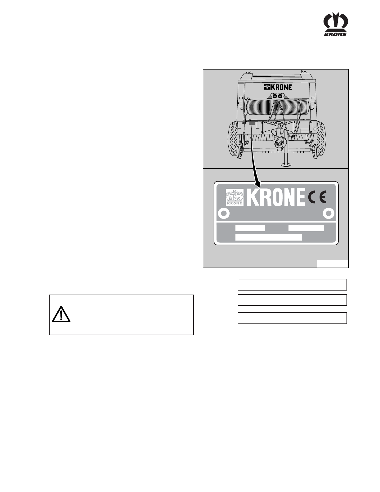
Operation in Accordance with
Specifications
The round baler is designed solely for normal agricultural
use(operation in accordancewithspecifications).
Anyuseofthemachineforotherpurposesisdeemedtobe
not in accordance with specifications. The manufacturer
bearsnoresponsibilityforanyresultingdamage;suchuse
is entirely at the operator´s risk.
Use in accordance with specifications also includes
adherence to the operating, maintenance and service
instructionsprescribedbythe manufacturer.
Theroundbalermustonlybeused,maintainedandrepaired
by personnel who are acquainted with the machine and
havebeen informedofthe dangersinvolved.
Theapplicableaccidentpreventionregulationsandallother
generally recognized safety, health and road traffic
regulationsmustbeadheredto.
Any unauthorized alterations to the machine render any
liabilityfordamageundertakenbythemanufacturernulland
void.
II. General

7
21.Only switch on equipment when all protective devices
are fitted and in protection position!
22.Personsare notallowed toenterthe workingarea!
23.Keep clear of the area of rotation and swing of the
equipment!
24.Hydrauliccontrolsmustonlybeoperatedifnopersons
are in the swing area!
25.Poweroperatedparts(e.g.byhydraulics)containdanger
points which can cause injury by bruising and,
grazing!
26.Makesurethatnopersonnelgobetweenthetractorand
theimplementunlessthetractorisprotectedfromrolling
by the parking brake and/or wheel blocks!
Trailedimplements
1.Secure theimplementagainst unintentional move-
ments.
2. Do not exceed the maximum load permissible on the
3-pointlinkage,drawbarorhitch.
3. In the case of trailed implements sufficient freedom
of motion must be provided at the hitch point.
6. Always ensure correct assembly and guarding of the
P.T.O. shaft!
7. Protect the P.T.O. shaft guard from rotating with the
shaft by fitting the chains!
8. Beforeswitchingonthepowertake-offshaft,makesure
thatthep.t.o.speedofthetractormatchesthepermitted
speed of the implement!
9. WhenusingthetravelPTOshaft,takeintoaccountthat
the shaft speed is dependent upon the speed of travel
and the direction of rotation is reveresed when the
tractorreverses.
10.Beforeswitchingonthepowertake-offshaft,makesure
that nobody is in the danger area of the implement!
11.Neverswitchonthepowertakeoffshaftwhenthetractor
engine is turned off!
12.Anyworkonthepowertake-offshaftmayonlybecarried
outwhennobodyisintheareaoftherotatingpowertake-
off shaft or P.T.O. shaft.
13.The power take-off shaft should always be turned off
when the angle is too great or the p.t.o. shaft is not
required!
14.Danger! Working elements continue to rotate after the
power take-off shaft is turned off! Do not approach the
machineduringthistime!Workmayonlybecarriedout
onthemachinewhenthemachineisfullystationaryand
the rotating parts have been secured by the parking
brake.
15.Cleaning, lubrication or adjustment of the P.T.O. shaft
oranyequipmentdrivenbythepowertake-offshaftmay
onlybecarriedoutwhentheP.T.O.shaftandtheengine
are turned off and the ignition key has been removed!
Rotatingpartsmustbesecuredwiththeparkingbrake.
16.PlacethedetachedP.T.O.shaftonthesupportbracket
provided!
17.After removing the P.T.O. shaft, place the protective
cover on the stub of the power take-off shaft!
18.Anydamagemustberepairedimmediatelybeforeany
work is carried out with the attachment!
Power take-off shaft operation
1. Only the P.T.O. shafts prescribed by the manufacturer
may be used!
2. Both male and female guard tubes and cones of all
P.T.O. shafts must be fitted and in good condition!
3. ObservethetubeoverlapprescribedforP.T.O.shaftsin
transportandoperatingposition!
4. Before installing or removing the P.T.O. shafts, make
suretoturnoff thepower take-offshaft andthe engine,
and remove the ignition key!
5. When using P.T.O. shafts with overload or free wheel
clutches that are not covered by the guards on the
tractor,theoverloadorfreewheelclutchesmustbefixed
on the implement side!

8
4. When there are functional hydraulic connections
betweenthemachineandtheimplement,allcoupling
sleevesandplugsmustbemarkedtopreventoperating
errors.Iftheconnections areswitched,thefunctions
are reversed (e.g. lifting and lowering) – this can
cause accidents!
5. Hydraulichosesmustbecheckedregularly,andthey
must be replaced if they are damaged or worn.
Replacement hoses must conform to the technical
requirementsoftheimplementmanufacturer!
6. When tracing leaks, suitable aids should be used
to prevent injury!
7. Fluidleaking underhigh pressure(hydraulic oil)can
penetrate the skin and cause serious injury! When
injuryoccurs,consultadoctorimmediately!Dangerof
infection!
8. Before carrying out any work on the hydraulic sys-
tems, lower the pick-up to the ground, depressurize
the system and turn off the engine!
Tyres
1. When working on the tyres, make sure that the
machine is safely supported and can not roll (wheel
blocks).
2. Fitting of wheels and tyres requires sufficient
knowledgeandcorrectequipment!
3. Repairworktotyresandwheelsmustonlybecarried
out by specialist personnel, and only with the correct
equipment!
4. The tyre pressure must be checked regularly! The
recommendedpressuremustbeadheredto!
Hydraulic System
1. The hydraulic system is pressurized!
2. When connecting hydraulic cylinders and motors,
make sure that the hydraulic hoses are correctly
coupled!
3. When connecting hydraulic hoses to the tractor´s
hydraulic system, make sure that all pressure has
beenreleasedfromthe hydraulics of boththetractor
andtheimplement!
Maintenance
1. Repair, maintenance and cleaning work and the
correctionofmalfunctionsmustalwaysbecarriedout
only when the drive is turned off and the engine is at
astandstill!Removetheignitionkey!Applytheparking
brake.
2. Nutsandboltsmustbecheckedregularlyfortightness,
and tightened if necessary!
3. Whencarryingoutmaintenanceworkonthemachine
in a lifted position, it must always be supported on
suitable jacks.
4. When replacing fittings that contain cutting blades,
always use suitable tools and gloves!
5. Oil, grease and filters must be correctly disposed of!
6.Thepowersupplymustalwaysbedisconnectedbefore
any work is carried out on the electrical system!
7. Ifprotectivedevicesaresubjecttowear,theymustbe
checkedregularly andreplaced ingood time!
8. Whenelectricweldingiscarriedoutonthetractorand
any fitted attachments, the cables must be dis-
connectedfromthegenerator andbattery!
9. Replacement parts must conform at least to the
technicalrequirementsdefinedbythemanufacturer!
The best guarantee is to use only original KRONE
parts!
10.Where gases are stored, only refill with nitrogen.
Dangerofexplosion!

9
KR 130
123 4
567
10 11
13 14 15
274 948-0 (1x) 939 194-1 (2x) 939 223-2 (1x)274 947-0 (1x)
942 111-0 (1x) 942 132-0 (1x)
273 506-1 (1x)
277 448-1 (1x) 277 449-1 (1x) 939 179-0 (3x)
(2x)
Positions of the Warning Signs
939 352-1 KR 130
939 347-1 KR 160
(1x)
12 939 468-1 (1x)
16 939 327-0 (2x)
17 939 308-1 (1x)
441 071-2 3,0 bar
441 072-2 3,5 bar
441 073-2 4,0 bar
441 074-2 4,5 bar
1
8h
2
50h
1
4
24h
24h
100h
5
24h
100h
6
24h
50h
24h
7
100h
8
24h
9
24h
24h
24h
277 448-1
24h
24h
24h
RE RE RE RE
LI
LI
LI
LI
LI
24h
24h
RE
LI
24
24h
LI
24h
23
RE
24h
2
24h
1
KR160
3
2
1
0
3
2
1
0
4
24h
100h
5
24h
100h
6
24h
50h
24h
7
100h
8
24h
277 449-1
24h
24h
RE
RE RE
RE
LI
LI
LI LI
24h
24h
24h
24h
LI
24h
24h
24h
LI
RE
24h
23
RE
24
24h
LI
KR 160
3
2
1
0
3
2
1
0
3
12
6
17
4
11
16
1
5
2
15
7
10
14
15
13
8
RI+LE
RI+LE
18
8939 361-1 (2x)
18 942 038-1 (1x)
942 038-1
273 506-1

10
1. Introduction
The KRONE Round Baler is equipped with all safety devices (guards). Not all danger areas in this machine can be
rendered completely safe as the machine must remain functional. You will find corresponding danger signs on the
machine which refer to the remaining danger.
We have represented the danger signs in the form of so-called warning symbols. You will find important notes on the
positions of these danger signs as well as their meaning and supplementary information below!
Familiarise yourself with the meaning of the adjacent warning symbol. The adjacent text and the
selected fixing point on the machine give information on the special danger areas in the machine.
1.1 Positions of the Warning Signs
1
Order No. 939 100-4 (1x)
2
While parts are moving,
never reach into areas where
there is a risk of being
crushed.
Order No. 942 196-1 (2x)
The PTO shaft speed must not exceed
540 rpm!
The operating pressure in the hydraulics
system must not exceed 200 bar.
KR 160
3
2
1
0
3
2
1
0
43
4
8
1
2
5
RH + LH
RH + LH
6RH + LH
7
9
RH +
LH
939 100-4
MAX. 540/min
MAX. 200 bar

11
Never reach into the pick up
area when the tractor engine
is running and the PTO shaft
is connected.
Order No. 939 407-1 (2x)
5
Order No. 939 125-1 (1x)
Do not reach into the danger
area beneath the wrapping
mechanism before the knives
have been brought into the
safety position.
3
Read and observe the
operating instructions.
Order No. 939 471-1 (1x)
6
Oerder No. 939 521-1 (2x)
Do not step under the raised
tail gate before the shut-off
tap on the cylinder on the tail
gate has been closed.
Order No. 939 520-1 (2x)
Danger - rotating auger.
(Only for pick ups with lateral
augers)
8
Order No. 939 529-0 (2x)
Accumulator is under gas and oil pressure.
Repair only possible by using replacement..
7
4
Order No. 942 002-4 (2x)
Close the guard before
putting into operation.
9

12
Units KR 130 Mini-Stop KR 160 Mini-Stop
Standard
pick up wide pick up Standard
pick up wide pick up
Length mm 3700 3700 3900 3900
Width mm2250229022802290
Height mm 2050 2090 2330 2330
Gauge mm 1950 1950 1950 1950
Tyres
10.0/75-15.3/8 ply
11.5/80-15.3/10 ply
15.0/55-17/10 ply
11.5/80-15.3/10 ply
15.0/55-17/10 ply
11.5/80-15.3/10 ply
15.0/55-17/10 ply
11.5/80-15.3/10 ply
15.0/55-17/10 ply
pick up
reach mm 1400 1800 1400 1800
Weight approx kg 1730 1920 1950 2140
Bale dimensions mm ø 1200 x 1200 ø 1200 x 1200 ø 1500 x 1200 ø 1500 x 1200
Power requirement
approx. kW/PS 25/34 25/34 29/40 29/40
Drive speed rpm 540 540 540 540
Overload coupling
(PTO shaft) Nm 800 1000 1000 1000
1.2 Technical Data

13
Storage of Bales
Wrapping Material Data
• According to § 41 of the German Regulations Authorising the Use of Vehicles for
Road Traffic, the empty weight of the towing vehicle (tractor) must be at least as
much as the empty weight of the round baler .
• Road journeys are only permitted with an empty bale chamber.
• When operating the baler in fields, the total weight must not exceed 2980 kg and
the supported load (on the tractor hitch) 450 kg.
Storage Binding material Rwine strength m/kg
open air Synthetic twine 400-600
indoors Sisal twine 150-330
Wrapping material Dimensions in mm
Width 1250 ± 5
Sleeve length 1250-1270
Inner sleeve diameter 75 bis 80
Roll diameter max. 310

14
1.3 Working Methods and Operating Principles of the KR 130 und KR 160
Round Balers
The round baler compresses crops such as hay, straw, grass silage etc. into round bales. On completion of the baling
procedure the bale is wrapped with twine, net or synthetic foil, depending on the type of wrapping material selected.
Due to their form, the round bales have good storage properties, can be transported simply and can be processed
further with ease.
The working method can be described as follows:
The crop is collected into a swath and taken in by the pick up, transported to the centre by the augers (only for wide
pick ups) and enters the bale chamber via the transport roller. In the bale chamber the crop is turned by the rotating
roller panel and rolled up. A roller-shaped round bale forms as the crop continues to enter. The bale becomes
increasingly compressed as more crop is fed into the round baler. Volume and baling pressure gauges are located on
the left and right in the front side of the baler for the corresponding side of the bale. A soon as the set baling pressure
on the baling pressure preselection gauge is reached, the wrapping process is started. Depending on the type of
equipment, the wrapping process can be started hydraulically or mechanically by hand using an actuating cord. On
completion of the wrapping process, the final round bale is transported through the open tail gate out of the round
baler and set down. The idle time during use can be reduced when closing the tail gate, due to the special design of
the bale ejector as a straw trap. This increases the efficiency of the round baler.

15
• Always switch off the PTO shaft when undertaking maintenance, care and repair work.
• Switch off the engine and remove the ignition key.
• Only use PTO shafts specified by the manufacturer which have an appropriate overload
coupling.
• Only attach and detach the PTO shaft when the drive shaft is switched off, the engine is
switched off and the ignition key has been removed!
• Lay hydraulic hoses, electric cables and synthetic cords such that they are not under
tension and do not come into contact with the tractor wheels when driving round
corners.
• Take particular care on and around the tractor and the round baler when attaching
and detaching the round baler!
2. Preparing the Round Baler
2.1 Special Notes on Safety
The maximum drive speed for the round baler is 540 rpm.
Switch off the PTO shaft as soon as the round baler jams.
2.2 Adapting the Swinging Drawbar to the Tractor
Theswinging drawbaronthe roundbaleris designedforthe variousmethods of attaching(above inthree-point
linkage; below e.g. swinging drawbar). It must be mounted and adjusted in accordance with the different attachment
options for the tractor.
When mounting anything on the swinging drawbar always observe the following:
• The teeth in the slots must be in the same position on both sides of the swinging drawbar.
• First tighten the screw in the round holes. Make sure that the teeth in the slots mesh.
• Only then should the screws in the slots be tightened.
• Before starting work park the round baler on firm ground. Secure from rolling away.
• Particular care is required when attaching the round baler to the tractor. Make sure that
there is nobody in the danger area round the tractor and round baler.
• After attaching successfully, switch off the engine and remove the ignition key.
• Secure the tractor and the round baler from rolling away.

16
Mounting the Swinging Drawbar for Bottom
Attachment
Mounting the Swinging Drawbar for Top
Attachment
Height Adjustment of the Swinging
Drawbar
• Attach the round baler.
• Leave the machine on the jack
stands (4).
• Loosen the fastening screws (3) - do
not take them out.
• Bring the machine into the specified
position by turning on the jack
stands.
• Tighten up the screws in the order
described above.
Mount the swinging drawbar (1) in the upper attachment
holes in the brackets (2) on the front cross carrier. The
height adjustment of the swinging drawbar is made as
described below in this chapter.
Rotate the swinging drawbar (1) through 180 degrees
about the lateral axis and mount it in the lower holes in
the brackets (2).
For optimum crop collection by the pick up, the round
baler must be attached horizontally to the tractor, if
necessary tilted forwards slightly. A corresponding fine
adjustment of the swinging drawbar (1) can be made at
the slots (2). This adjustment can be made while the
baler is coupled to the tractor.
KR-0-047
4
3
1
2
KR-0-001
2
1
KR-0-002
12

17
2.3 Adapting the PTO Shaft
Attach the round baler to the tractor to adapt the length
of the PTO shaft. The PTO shaft is at its shortest when
going round tight corners. To measure, take the PTO
shaft apart and and slide the two halves (1) and (2) on
to the machine and the tractor. The exact procedure for
adapting the length can be found in the PTO shaft
manufacturer's operating instructions.
2.4 Cleaning and Checking the Double Twine Guide Starter Rollers
Before working on the starter rollers, switch off the PTO shaft, switch off the engine and
remove the ignition key. Secure the tractor and the round baler from rolling away.
The starter rollers are wrapped in adhesive tape to
protect them from corrosion. Remove the adhesive tape
and clean the rollers of any residual adhesive. The
pressure rollers (3) must be able to be rotated easily.
Turn the drive roller (1) to check. If the pressure rollers
do not rotate or only rotate with difficulty, refer to the
notes in the chapter "Care and Maintenance".
• Before working on the PTO shaft, switch off the engine and remove the ignition key.
• Secure the tractor together with the round baler from rolling away.
• When adapting the PTO shaft there must be nobody between the tractor and the round
baler.
KR-0-079
1
2
1 2
3KR-0-099

18
Position
Tyres
10.0 / 75 - 15.3
11.5 / 80 - 15.3
15.0 / 55 - 17.0
if the machine is to
be 40 mm lower
2.5 Adjusting the Height of the Wheel
Hubs
• Park the round baler on firm ground
and secure from rolling away with
wheel chocks.
• To jack up the round baler, use a
suitable jack and jack stands.
• Risk of crushing from falling
components.
For adaption to different tyre sizes and working
conditions, the height of the wheel hubs can be
adjusted on both sides of the round baler.
To adapt: • Take off the tyres (make sure to observe
the "Tyres" section in the chapter "Care
and Maintenance").
• Loosen the fastening screws (2) in the
flange plate (1), take it out and re-attach the
flange plate in a different position.
• Tighten up the screws again (tightening
moments are listed in the chapter "Care
and Maintenance").
a
b
b
c
• Particular care is required on and
around the tractor and the round
baler when attaching and detaching
the round baler!
• Observe the tractor's maximum
permissable supported and trailer
loads .
2.6 Putting the Round Baler into Operation
Attach the round baler to the attachment device, e.g. to
the attachment linkage (1), and secure as directed.
Attach the actuating cord (2) to the tractor. Make sure
that the actuating cord is not under tension and does
not come into contact with the tyres when driving round
corners.
This also applies for bottom attachment, not shown
here.
Recommended
2.6.1 Attaching the Round Baler to the
Tractor
KR-0-044
2
1
KR-0-103
2
1
2
2
c
b
a
This manual suits for next models
1
Table of contents
Other Krone Lawn And Garden Equipment manuals

Krone
Krone Comprima F 155 XC User manual

Krone
Krone Comprima CF 155 XC User manual

Krone
Krone Fortima F 1250 MC User manual

Krone
Krone Comprima F 125 Installation instructions

Krone
Krone Fortima V 1500 User manual

Krone
Krone Vario Pack 1510 User manual

Krone
Krone COMPRIMAF F 125 Installation instructions

Krone
Krone Comprima F 155 XC User manual

Krone
Krone KR 130-MINISTOP User manual

Krone
Krone Comprima F 125 User manual