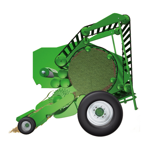
Krone Fortima F 1250 MC User manual

Original operating instructions
Round baler
Fortima F 1250 (MC)
Fortima F 1600 (MC)
Fortima V 1500 (MC)
Fortima V 1800 (MC)
(from serial no.: 848 920)
Order no.: 150 000 135 05 en
14.05.2014

Foreword
2
Pos: 1 /BA/Konformitä tserklärungen/ Rundballenpressen/For tima F 1250 (MC), F1600 (MC), V1500 (MC), V1800 (MC) @ 113\m od_1338368042562_78.doc x @ 1000614 @ @ 1
CV0
EC Declaration of Conformity
We Maschinenfabrik Bernard Krone GmbH
Heinrich-Krone-Str. 10, D-48480 Spelle
hereby declare as manufacturer of the product named below, on our sole responsibility,
that the
Machine: Krone Round Baler
Typ / Types: Fortima F 1250 / Fortima F 1250 MultiCut
Fortima F 1600 / Fortima F 1600 MultiCut
Fortima V 1500 / Fortima V 1500 MultiCut
Fortima V 1800 / Fortima V 1800 MultiCut
to which this declaration refers is in compliance with the relevant provisions of
EG-directive 2006/42/EG (machines) and EG directive 2004/108/EG (EMV).
The signing Managing Director is authorised to compile the technical documents.
Spelle, 08.05.2014
Dr.-Ing. Josef Horstmann
(Managing Director, Design and Development)
Year of manufacture: Machine No.:
Pos:2 /LayoutModule /---------------Seitenumbruch----------------@ 0\mod_1196175311226_0.doc x@ 4165 @ @ 1

Foreword
3
Pos: 3.1 /Überschri ften/Überschri ften 1/U-Z/Vorwort @ 0\mod_ 1195627720123_78.doc x @ 982 @ 1 @ 1
1 Foreword
Pos: 3.2 /BA/Vor wort/Rundballenpressen/ Verehrter Kunde Rund ballenpresse @ 27\mod_12 46526159413_78.doc x@ 267781 @ @ 1
Dear Customer!
By purchasing the round baler, you have acquired a quality product from KRONE.
We are grateful for the confidence you have invested in us in buying this machine.
It is important to read the operating instructions very carefully before you start operating the
machine to allow you to use the round baler to its full capacity.
The contents of this manual are laid out in such a way that you should be able to perform any
task by following the instructions step by step. It contains extensive notes and information about
maintenance, how to use the machine safely, secure working methods, special precautionary
measures and available accessories. This information and these instructions are essential,
important and useful for the operational safety, reliability and durability of the round baler.
Pos: 3.3 /BA/Vor wort/Rundballenpressen/ Weiterer Verlauf Rundballenpresse @ 27\mo d_1246526537241_78.doc x @ 267806 @ @ 1
Note
In the operating instructions which follow, the round baler will also be referred to as the
"machine".
Pos: 3.4 /BA/Vor wort/Beachten Sie für Maschi ne @ 0\mod_1195626904076_7 8.docx @ 944 @ @ 1
Please note:
The operating instructions are part of your machine.
Only operate this machine after you have been trained to do so and according to these
instructions.
It is essential to observe the safety instructions!
It is also necessary to observe the relevant accident prevention regulations and other generally
recognised regulations concerning safety, occupational health and road traffic.
All information, illustrations and technical data in these operating instructions correspond to the
latest state at the time of publication.
We reserve the right to make design changes at any time and without notification of reasons.
Should you for any reason not be able to use these operating instructions either wholly or
partially, you can receive a replacement set of operating instructions for your machine by
quoting the number supplied overleaf.
We hope that you will be satisfied with your KRONE machine.
Maschinenfabrik Bernard Krone GmbH
Spelle
Pos:4 /LayoutModule /---------------Seitenumbruch----------------@ 0\mod_1196175311226_0.doc x@ 4165 @ @ 1

Table of Contents
4
Pos: 5 /Überschrif ten/Überschrif ten1/ F-J/Inhaltsverzeic hnis @ 31\mod_12519699 52727_78.docx @ 302165 @ 1 @ 1
2 Table of Contents
Pos: 6 /BA/Inhaltsver zeichnis Sprachenne utral @ 10\mod_1221574899 104_0.docx @ 135495 @ @ 1
1Foreword .................................................................................................................................................3
2Table of Contents ...................................................................................................................................4
3Introduction...........................................................................................................................................10
3.1Purpose of Use................................................................................................................................ 10
3.1.1Contact......................................................................................................................................... 10
3.2Identification Plate ........................................................................................................................... 11
3.3Information Required for Questions and Orders.............................................................................. 11
3.4Intended use.................................................................................................................................... 12
3.5Technical data ................................................................................................................................. 13
4Safety.....................................................................................................................................................17
4.1Identifying Symbols in the Operating Instructions........................................................................... 17
4.2Identification of the hazard warnings............................................................................................... 17
4.2.1Personnel Qualification and Training........................................................................................... 18
4.2.2Dangers in Case of Non-compliance with the Safety Instructions............................................... 18
4.2.3Safety-conscious work practices ................................................................................................. 18
4.3Safety Instructions and Accident Prevention Regulations............................................................... 19
4.4Hitched Implements......................................................................................................................... 20
4.5PTO operation ................................................................................................................................. 21
4.6Hydraulic system ............................................................................................................................. 22
4.7Tyres................................................................................................................................................ 22
4.8Maintenance .................................................................................................................................... 23
4.9Working in the vicinity of power transmission lines ......................................................................... 23
4.10Unauthorised Conversion/Modification and Spare Parts Production.............................................. 24
4.11Inadmissible Modes of Operation.................................................................................................... 24
4.12Safety Instructions on the Machine ................................................................................................. 24
4.13Introduction...................................................................................................................................... 25
4.14Position of the Adhesive Safety Stickers on the Machine............................................................... 26
4.14.1Re-Ordering the Adhesive Safety and Information Labels...................................................... 32
4.14.2Affixing the Adhesive Safety and Information Labels.............................................................. 32
5Commissioning.....................................................................................................................................34
5.1Before initial start-up........................................................................................................................ 35
5.2Assembling the bale ejector............................................................................................................. 41
5.3Adjusting the drawbar height........................................................................................................... 46
5.4PTO shaft......................................................................................................................................... 49
5.4.1Attaching the guard cup for universal shaft................................................................................. 49
5.4.2Mounting the PTO shaft on the machine side ............................................................................. 50
5.4.3Length adjustment....................................................................................................................... 53
5.5Hose holder assembly..................................................................................................................... 54
5.5.1Net brake ..................................................................................................................................... 55
5.6Attaching the Triangle Spotlights..................................................................................................... 55
6KRONE operation terminal Beta .........................................................................................................56
6.1Attachment of control unit................................................................................................................ 57
6.1.1Connecting Control Unit............................................................................................................... 57
6.2Description of the keys .................................................................................................................... 58
6.3Operational Readiness.................................................................................................................... 59
6.4Basic Screen.................................................................................................................................... 60

Table of Contents
5
6.4.1Functions of Keys 1 - 3................................................................................................................ 60
6.5Selecting manual or automatic mode.............................................................................................. 61
6.5.1Selecting Pick-up or Blade Base ................................................................................................. 61
6.5.2Displays in the Main Window....................................................................................................... 62
6.5.3Messages..................................................................................................................................... 64
6.5.4Setting Bale Firmness.................................................................................................................. 65
6.5.5Setting Bale Diameter.................................................................................................................. 66
6.6Menu Level...................................................................................................................................... 67
6.6.1Short overview............................................................................................................................. 67
6.6.2Bringing up a Menu Level............................................................................................................ 68
6.7Main menu 1 "Settings" ................................................................................................................... 69
6.7.1Menu 1-1 "Contrast" .................................................................................................................... 70
6.7.2Menu 1-3 "Number of Net Winds"................................................................................................ 71
6.7.3Menu 1-4 „Sensitivity of Direction Display“.................................................................................. 72
6.7.4Menu 1-5 „Pre-Signalling"............................................................................................................ 74
6.7.5Menu 1-6 „Correction Filling"....................................................................................................... 76
6.7.6Menu 1-7 "Select type of tying".................................................................................................... 78
6.7.7Menu 1-8 "Number of twine wraps (only for twine tying with magnetic transmission)"............... 80
6.7.8Menu 1-8-1 „Inserting Twine Wraps"........................................................................................... 81
6.7.9Menu 1-8-3 „Cutting Off Twine Wraps "....................................................................................... 82
6.7.10Menu 1-9 „Tying Start Delay" .................................................................................................. 83
6.8Main menu 2 "Counters".................................................................................................................. 84
6.8.1Menu 2-1 "Customer counters".................................................................................................... 85
6.8.2Menu 2-2 "Total bale counter"..................................................................................................... 87
6.9Main menu 3 „Manual operation“..................................................................................................... 89
6.10Main menu 4 "Service" .................................................................................................................... 91
6.10.1Menu 4-2 "Manual Sensor Test".............................................................................................. 92
6.10.2Menu 4-4 "Manual Actuator Test"............................................................................................ 97
6.11Main menu 5 "Info" ........................................................................................................................ 100
6.12Main Menu 6 „Technician“............................................................................................................. 101
6.13Alarm messages............................................................................................................................ 102
6.13.1Note and messages............................................................................................................... 103
6.13.2Physical messages................................................................................................................ 104
6.13.3General Messages................................................................................................................. 105
7KRONE ISOBUS Terminal..................................................................................................................106
7.1Installing the terminal into cabin .................................................................................................... 107
7.2ISOBUS Short Cut Button.............................................................................................................. 108
7.2.1Display / Touchscreen............................................................................................................... 109
7.2.2Connecting the Terminal (on tractors with integrated ISOBUS system) ................................... 110
7.2.3Connecting the terminal (on tractors without ISOBUS system)................................................. 111
7.2.4Switching the terminal on / off when the machine is not connected.......................................... 112
7.2.5Switching the terminal on / off when the machine is connected................................................ 113
7.3Basic Screen.................................................................................................................................. 114
7.3.1Setting the Setpoint Bale Firmness ........................................................................................... 117
7.3.1Setting the Target Bale Diameter .............................................................................................. 118
7.4Messages....................................................................................................................................... 119
7.5Menu Level.................................................................................................................................... 120
7.5.1Short Overview.......................................................................................................................... 120
7.5.2Calling up the menu level .......................................................................................................... 121

Table of Contents
6
7.6Main Menu 1 „Settings“.................................................................................................................. 122
7.6.1Menu 1-3 "Number of net winds"............................................................................................... 123
7.6.2Menu 1-4 "Sensitivity of direction display"................................................................................. 124
7.6.3Menu 1-5 „Pre-Signalling".......................................................................................................... 125
7.6.4Menu 1-6 „Filling Correction"..................................................................................................... 127
7.6.5Menu 1-7 "Select type of tying".................................................................................................. 129
7.6.6Menu 1-8 „Number of Twine Wraps"......................................................................................... 130
7.6.7Menu 1-9 „Tying Start Delay" .................................................................................................... 131
7.7Main menu 2 "Counters"................................................................................................................ 132
7.7.1Menu 2-1 „Customer Counter“................................................................................................... 133
7.7.2Menu 2-2 „Total Bale Counter“.................................................................................................. 135
7.8Main menu 3 "Manual operation" .................................................................................................. 136
7.8.1Menu 3-2 "Position of net motor"............................................................................................... 137
7.9Main menu 4 "Service" .................................................................................................................. 138
7.9.1Menu 4-2 "Manual sensor test".................................................................................................. 139
7.9.2Menu 4-4 Manual actuator test.................................................................................................. 145
7.10Main Menu 5 „Information“............................................................................................................. 149
7.11Main Menu 6 Technician................................................................................................................ 150
7.12Main Menu 7 ISOBUS ................................................................................................................... 151
7.12.1Menu 7-1 Virtual Terminal (VT) ............................................................................................. 152
7.12.2Menu 7-1-1 Switching Day-Night Lighting Display ................................................................ 153
7.12.3Menu 7-1-4 Switch to different terminal................................................................................. 154
7.13Menu 7-4 ISOBUS Diagnostics ..................................................................................................... 155
7.13.1Menu 7-4-2 Diagnostics Auxiliary Functions (AUX)............................................................... 156
7.14Alarm messages............................................................................................................................ 157
7.14.1Acoustic warnings.................................................................................................................. 158
7.14.2Note and messages............................................................................................................... 159
7.14.3Physical messages................................................................................................................ 160
7.14.4General Messages................................................................................................................. 161
8ISOBUS operation ..............................................................................................................................162
8.1Mounting ISOBUS Terminal .......................................................................................................... 163
8.1.1Connection Terminal to Tractor................................................................................................. 163
8.1.2Connection Tractor to Machine.................................................................................................. 163
8.2Differing functions to KRONE ISOBUS terminal CCI .................................................................... 164
8.3ISOBUS „Auxiliary“-function (AUX) ............................................................................................... 165
8.3.1Example of joystick assignment for Fendt (default setting)....................................................... 166
9Start-up................................................................................................................................................167
9.1Mounting onto the Tractor.............................................................................................................. 168
9.2Hydraulics...................................................................................................................................... 169
9.2.1Special Safety Instructions ........................................................................................................ 169
9.2.2Connecting the hydraulic lines................................................................................................... 170
9.3Hydraulic brake (Export)................................................................................................................ 171
9.4Hydraulic brake (auxiliary brake)................................................................................................... 171
9.4.1Install the PTO shaft.................................................................................................................. 172
9.5Compressed Air Connections for the Compressed Air Brake....................................................... 174
9.6Electrical connections.................................................................................................................... 175
9.7Using the safety chain ................................................................................................................... 176
10Driving and Transport........................................................................................................................178

Table of Contents
7
10.1Preparations for road travel........................................................................................................... 178
10.1.1Raise the pick-up................................................................................................................... 179
10.1.2Checking the parking support................................................................................................ 180
10.1.3Checking the lighting system................................................................................................. 180
10.2Parking........................................................................................................................................... 181
10.2.1Secure the machine against the possibility of rolling back.................................................... 181
10.2.2Lowering the parking support ................................................................................................ 182
10.2.3Disconnecting the PTO shaft from the tractor ....................................................................... 182
10.2.4Disconnecting the supply lines .............................................................................................. 183
11Operation.............................................................................................................................................185
11.1Settings Before Starting Work ....................................................................................................... 186
11.2Travelling speed ............................................................................................................................ 187
11.3Filling the Bale Chamber ............................................................................................................... 188
11.4Wrapping and Depositing Bales .................................................................................................... 189
11.5After Baling .................................................................................................................................... 189
11.6Shear screw for pick-up drive........................................................................................................ 190
11.7Splash guard.................................................................................................................................. 191
11.8Pick-up........................................................................................................................................... 192
11.9Default Setting (Working Height Setting)....................................................................................... 192
11.10Roller crop guide........................................................................................................................ 194
11.11Adjusting the baffle plate ........................................................................................................... 195
11.12Preselecting Baling Pressure..................................................................................................... 196
11.13Cutting system........................................................................................................................... 197
11.13.1General Aspects.................................................................................................................... 197
11.13.2Chop length............................................................................................................................ 198
11.13.3Zero position of the cutter...................................................................................................... 201
11.13.4Blade Quick-Fit Device Blade................................................................................................ 203
11.13.5Adjust blade control shaft ...................................................................................................... 205
11.13.6Zero position of the cutter...................................................................................................... 207
11.14Removing the Crop Blockages in the Crop Collection Area...................................................... 211
11.14.1Crop blockage under feed rotor/cutting rotor......................................................................... 211
11.14.2Crop blockage at pick-up....................................................................................................... 215
11.15Reversing................................................................................................................................... 216
11.16Assembly and disassembly of the bale ejector.......................................................................... 218
11.17Floor conveyor chain ................................................................................................................. 220
11.18Twine tying/twine tying and net wrapping.................................................................................. 221
11.18.1Twine tying parts.................................................................................................................... 221
11.18.2Twine tying and net wrapping parts....................................................................................... 222
11.18.3Tying function ........................................................................................................................ 223
11.19Setting the tying twine in place.................................................................................................. 224
11.20Net Wrapping............................................................................................................................. 230
11.20.1Net wrapping parts................................................................................................................. 230
11.21Inserting the Net Roll................................................................................................................. 231
12Settings ...............................................................................................................................................235
12.1Tying unit ....................................................................................................................................... 236
12.1.1Adjusting the twine limiter...................................................................................................... 236
12.1.2Adjusting the twine brake....................................................................................................... 237
12.1.3Loosening the twine brake..................................................................................................... 238
12.1.4Adjusting the idler roller......................................................................................................... 239

Table of Contents
8
12.1.5Adjusting the sensor.............................................................................................................. 239

12.1.6Selecting the type of tying...................................................................................................... 240
12.1.7Adjusting the net brake.......................................................................................................... 240
12.1.8Adjusting the additional net brake ......................................................................................... 241
12.1.9Loosening the net brake........................................................................................................ 242
12.1.10Net spreader.......................................................................................................................... 242
12.1.11Adjusting the Magnetic Coupling (in Case of Twine Wrapping)............................................ 243
12.2Central chain lubrication system.................................................................................................... 244
12.2.1Display Central Chain Lubrication System............................................................................ 247
12.3Adjusting the Automatic Floor Conveyor Stop............................................................................... 249
12.3.1Adjusting the switching time .................................................................................................. 250
13Maintenance........................................................................................................................................251
13.1Special Safety Instructions ............................................................................................................ 251
13.2Spare Parts.................................................................................................................................... 251
13.3Overview........................................................................................................................................ 252
13.4Setting Tailgate Catch ................................................................................................................... 253
13.4.1Setting Lock Hook Blocker..................................................................................................... 254
13.5Setting Cutting Blade Net Tying Device ........................................................................................ 255
13.5.1Adjusting the cutting blades of the net wrap system ............................................................. 255
13.6Setting of the Scraper Rail to the Upper Spiral Roller................................................................... 256
13.7Grinding blades.............................................................................................................................. 257
13.8Sensors.......................................................................................................................................... 258
13.8.1Position of the Sensors.......................................................................................................... 258
13.8.2Adjusting the Sensors............................................................................................................ 262
13.8.2.1Namur sensor d = 12 mm.............................................................................................. 262
13.8.2.2Namur sensor d = 18 mm.............................................................................................. 262
13.8.3Central Position of Engine Sensor......................................................................................... 263
13.8.4Sensor Position Blade Shaft (Machines with Cutting Device)............................................... 264
13.9Tightening Torques........................................................................................................................ 265
13.10Tightening Torques (Countersunk Screws)............................................................................... 266
13.11Drawbar ..................................................................................................................................... 267
13.11.1Hitches on the Drawbar......................................................................................................... 267
13.12Main gearbox............................................................................................................................. 268
13.12.1Oil Level Check and Oil Change on Main Gearbox............................................................... 268
13.12.2Oil Level Check and Oil Change Intervals (Gearboxes)........................................................ 269
13.12.3Filling Quantities and Lubrication Designation for Gearboxes .............................................. 269
13.13Drive chains............................................................................................................................... 270
13.13.1Tensioning the Drive Chains.................................................................................................. 270
13.14Cleaning the Tensioning Arm Floor Conveyor Rear.................................................................. 277
13.15Shortening the floor conveyor chain.......................................................................................... 278
13.16Tyres.......................................................................................................................................... 280
13.16.1Checking and maintaining tyres............................................................................................. 281
13.16.2Tyre air pressure.................................................................................................................... 282
13.17Brakes........................................................................................................................................ 284
13.17.1Checking the brake setting.................................................................................................... 284
13.17.2Adjusting the cam brake........................................................................................................ 285
13.18Maintenance – brake system (special equipment).................................................................... 288
13.18.1Special Safety Instructions .................................................................................................... 288
13.18.2Coupling heads (non-interchangeable) ................................................................................. 289

Table of Contents
9
13.18.3Air filter for pipelines.............................................................................................................. 290
13.18.4Compressed-air reservoir...................................................................................................... 291
13.19Hydraulics.................................................................................................................................. 292
13.19.1Shut-off valve for tailgate....................................................................................................... 293
13.19.2Control block.......................................................................................................................... 294
13.19.3Emergency Manual Activation Electromagnetic Valves (MC Cutting System)...................... 295
13.19.4Replacing the Hydraulic Oil Filter .......................................................................................... 296
13.20Lifting ......................................................................................................................................... 298
13.20.1Lifting Eyes ............................................................................................................................ 298
13.20.2Lifting ..................................................................................................................................... 298
14Maintenance – lubrication .................................................................................................................299
14.1Special Safety Instructions ............................................................................................................ 299
14.2Lubricants ...................................................................................................................................... 300
14.3General aspects............................................................................................................................. 300
14.4Lubricating the PTO shaft.............................................................................................................. 300
14.5Lubrication points........................................................................................................................... 301
14.5.1Chain Lubrication System...................................................................................................... 307
15Placing in Storage ..............................................................................................................................308
15.1Special Safety Instructions ............................................................................................................ 308
15.2At the End of the Harvest Season................................................................................................. 309
15.3Before the Start of the New Season.............................................................................................. 310
15.3.1Maintenance work before the beginning of the new season................................................. 311
15.3.2Venting the overload coupling on the PTO shaft................................................................... 312
16Malfunctions - Causes and Remedies..............................................................................................313
16.1Special Safety Instructions ............................................................................................................ 313
16.2General malfunctions..................................................................................................................... 314
16.3Malfunctions on the central chain lubrication system.................................................................... 317
16.4Error Messages of KRONE Operation Terminal............................................................................ 318
17Appendix .............................................................................................................................................319
17.1Hydraulic System Circuit Diagrams............................................................................................... 319
17.2Electrical circuit diagram................................................................................................................ 321
18Index ....................................................................................................................................................322
Pos:7 /LayoutModule /---------------Seitenumbruch----------------@ 0\mod_1196175311226_0.doc x@ 4165 @ @ 1

Introduction
10
Pos: 8.1 /BA/Einlei tung/Einleitung @ 0\mod_1 195562498677_78.d ocx @ 416 @ 1 @ 1
3 Introduction
These operating instructions contain fundamental instructions. These must be observed in
operation and maintenance. For this reason, these operating instructions must be read by
operating personnel before commissioning and use, and must be available for easy reference.
Follow both the general safety instructions contained in the section on safety and the specific
safety instructions contained in the other sections.
Pos: 8.2 /Überschri ften/Überschri ften 2/U-Z/Verwendungsz weck @ 1\mod_120170724673 8_78.docx @ 54055 @ 12 @ 1
3.1 Purpose of Use
Pos: 8.3 /BA/Einlei tung/Maschinenüber sicht/Rundballen pressen/Verwendungsz weck Fortima F1250, F16 00, V1500, V1800 @ 113\mod_1 338368566201_78.doc x@ 1000672 @ 2 @ 1
Round balers Fortima F 1250 (MC)/F 1600 (MC) and Fortima V 1500 (MC)/V 1800 (MC) are
pick-up balers. They compact agricultural material such as hay, straw or grass silage into round
bales.
The round balers Fortima F 1250 (MC)/F 1600 (MC) are equipped with a fix bale chamber. The
fix bale chamber of Fortima F 1250 (MC) enables baling of round bales with a diameter of
approx. 1.25 m; whereas the bale chamber of Fortima F 1600 (MC) enables baling with a
diameter of approx. 1.55 m.
The round balers Fortima V 1500 (MC) and V 1800 (MC) are equipped with a variable bale
chamber.
The variable bale chamber of Fortima V 1500 (MC) enables baling of round bales with a
diameter of approx. 1.00 - 1.50 m; the variable bale chamber of Fortima V 1800 (MC) enables
baling with a diameter of approx. 1.00 - 1.80 m.
The width of the round bales amounts to 1.20 m. The round balers are equipped with quadruple
twine tying (with magnetic coupling) and/or net wrapping systems.
Pos: 8.4 /BA/Einlei tung/Maschinenüber sicht/Großpackenpr essen/Aufnahme und Pr essung nicht genannter Pressgüter @ 17\mod_123 6170563105_78.doc x @ 201591 @ @ 1
WARNING! – Intake and baling of pressing material not mentioned!
Effect: Damage to the machine
Collecting and baling materials that are not cited here is permitted only in agreement with the
manufacturer. The basic requirements in any case are swath form loading of the crops and
automatic intake by the Pick-up as it passes over them.
Pos: 8.5 /Überschri ften/Überschri ften 3/A-E/Ansprec hpartner @ 0\mod_119556939428 6_78.docx @ 839 @ 3 @ 1
3.1.1 Contact
Pos: 8.6 /BA/Adr essen/Adresse Maschinenf abrik KRONE Spelle @ 0\mod_1 195568531083_78.d ocx @ 734 @ 3 @ 1
Maschinenfabrik Bernard Krone GmbH
Heinrich-Krone-Strasse 10
D-48480 Spelle (Germany)
Telephone: + 49 (0) 59 77/935-0 (Head Office)
Fax.: + 49 (0) 59 77/935-339 (Head Office)
Fax.: + 49 (0) 59 77/935-239 (Spare parts - domestic)
Fax.: + 49 (0) 59 77/935-359 (Spare parts - export)
Email: [email protected]
Pos:8.7 /LayoutModule/---------------Seitenumbruch---------------- @0\mod_119617531 1226_0.docx @ 4165 @ @ 1

Introduction
11
Pos: 8.8 /Überschri ften/Überschri ften 2/K-O/Kennzeichnung @ 0\mod_1195564622099_ 78.docx @ 496 @ 2 @ 1
3.2 Identification Plate
Pos: 8.9 /BA/Einlei tung/Kennzeichnung/ Rundballenpressen/ Bild Maschinendate n Rundballenpresse @ 27\mod_1246532767116_7 8.docx @ 267975 @ 2 @ 1
KR004020
Fig. 1
The machine data are located on the type plate (1), which is located on the right-hand side of
the machine below the twine box.
Pos: 8.10 /BA/Einlei tung/Kennzeichnung/ Angaben für Anfr age und Bestellungen_Fahrze ugident-Nr. @ 0\ mod_1195565119708_78.doc x @ 515 @ 2 @ 1
3.3 Information Required for Questions and Orders
Type
Year of manufacture
Vehicle ID number
Note
The entire identification plate represents a legal document and should not be altered or
rendered illegible!
When asking questions concerning the machine or ordering spare parts, be sure to provide type
designation, vehicle ID number and the year of manufacture : To ensure that these data are
always available, we recommend that you enter them in the fields above.
Note
Authentic KRONE spare parts and accessories authorised by the manufacturer help to ensure
safety. The use of spare parts, accessories and other devices which are not manufactured,
tested or approved by KRONE will result in the revoking of the liability for damages resulting
thereof.
Pos:8.11 /LayoutModule/---------------Seitenumbruch----------------@ 0\mod_1196175311226_0.doc x@ 4165 @ 2 @ 1

Introduction
12
Pos: 8.12.1 /Überschr iften/Überschr iften 2/A-E/Bestimmu ngsgemäße Verwendung @ 103\ mod_1332169199326_78. docx @ 940071 @ 2 @ 1
Ver
3.4 Intended use
Pos: 8.12.2 /BA/Ei nleitung/Bestimmungsg emäßer Gebrauch/Rundb allenpresse/Bes timmungsgemäßer Gebrauc h Rundballenpresse @ 32\ mod_1253019678915_ 78.docx @ 308291 @ 2 @ 1
The round baler is built exclusively for customary use in agricultural work (intended use).
Pos: 8.12.3 /BA/E inleitung/Bestimmungsg emäßer Gebrauch/Nic ht bestimmungs gemäss @ 103\ mod_1332171672294_7 8.docx @ 940272 @ @ 1
Unauthorised modifications to the machine may have a negative effect on the machine
characteristics or safe and reliable use of the machine or may interfere with proper operation.
Unauthorised modifications shall therefore release the manufacturer of any liability for
consequential damage.
Pos:8.13 /LayoutModule/---------------Seitenumbruch----------------@ 0\mod_1196175311226_0.doc x@ 4165 @ @ 1

Introduction
13
Pos: 8.14 /BA/Einlei tung/Technische Date n/Technische Daten @ 0\ mod_1195566374865_78. docx @ 594 @ 2 @ 1
3.5 Technical data
All information, illustrations and technical data in these operating instructions correspond to the
latest state at the time of publication. We reserve the right to make design changes at any time
and without notification of reasons.
Pos: 8.15 /BA/Einlei tung/Technische Date n/Rundballenpress e/Technische Daten For tima F 1250 (MC) @ 227\mod_1392 733434134_78.doc x@ 18276 18 @ 2 @ 1
Fortima F 1250 / Fortima F 1250 MC
Axle Single axle Tandem axle
Pick-up (width) 2050 mm 2050 mm
Width approx. 11.5/80-15 2460 mm 2740 mm
15.0/55-17 2535 mm 2815 mm
19.0/45-17 2605 mm 2885 mm
500/50-17 2650 mm --
Permissible weights see information listed on identification plate
Track width 2150 mm 2430 mm
Tyres 11.5/80-15.3/10 PR
15.0/55-17/10 PR
19.0/45-17/10 PR
500/50-17/10 PR --
Length approx. 4100 mm
Height at 500/50-17 approx. 2465 mm
Bale
dimensions Diameter approx. 1250 mm
Width approx. 1200 mm
Power requirement approx. 36 kW (50 HP)
Drive speed (PTO shaft) 540 rpm
Max. permissible operating pressure of
hydraulic system 200 bar
Minimum oil quality Oil ISO VG 46
Max. oil temperature 80°C
Delivery capacity hydraulics min. 30 l/min
max. 60 l/min
Electrical
connections Lighting 12 volts – 7-pin plug
Operation 12 volts – 3-pin plug
Twine Open air storage Synthetic twine 400 - 1000 m/kg
Indoor storage Sisal twine 150 - 300 m/kg
Net Width 1250 ± 5 mm
Sleeve length 1250 - 1270 mm
Sleeve diameter 75 - 80 mm
Roll diameter max. 310 mm (3000 m roll)
Overload protection (universal shaft)
Cam-type clutch 540 rpm 1300 Nm (Fortima F 1250)
1500 Nm (Fortima F 1250 MC)
Overload protection (universal shaft)
Friction clutch 540 rpm 1300 Nm (Fortima F 1250)
Hydraulic
connections Open the tailgate 1 x single-action control unit
Raise pick-up or blade base
(MC) 1 x single-action control unit
Pos:8.16 /LayoutModule/---------------Seitenumbruch----------------@ 0\mod_1196175311226_0.doc x@ 4165 @ @ 1

Introduction
14
Pos: 8.17 /BA/Einlei tung/Technische Date n/Rundballenpress e/Technische Daten For tima F 1600 (MC) @ 227\mod_1392 733454061_78.doc x@ 18276 47 @ @ 1
Fortima F 1600 / Fortima F 1600 MC
Axle Single axle Tandem axle
Pick-up (width) 2050 mm 2050 mm
Width approx. 11.5/80-15 2460 mm 2740 mm
15.0/55-17 2535 mm 2815 mm
19.0/45-17 2605 mm 2885 mm
500/50-17 2650 mm --
Permissible weights see information listed on identification plate
Track width 2150 mm 2430 mm
Tyres 11.5/80-15.3/10 PR
15.0/55-17/10 PR
19.0/45-17/10 PR
500/50-17/10 PR --
Length approx. 4300 mm
Height (500/50-17) approx. 2600 mm
Bale
dimensions Diameter approx. 1550 mm
Width approx. 1200 mm
Power requirement approx. 40 kW (55 HP)
Drive speed (PTO shaft) 540 rpm
Max. permissible operating pressure of
hydraulic system 200 bar
Minimum oil quality Oil ISO VG 46
Max. oil temperature 80 °C
Delivery capacity hydraulics min. 30 l/min
max. 60 l/min
Electrical
connections Lighting 12 V – 7-pin plug
Operation 12 V – 3-pin plug
Twine Open air storage Synthetic twine 400 - 1000 m/kg
Indoor storage Sisal twine 150 - 300 m/kg
Net Width 1250 ± 5 mm
Sleeve length 1250 - 1270 mm
Sleeve diameter 75 - 80 mm
Roll diameter max. 310 mm (3000 m roll)
Overload protection (universal shaft)
Cam-type clutch 540 rpm 1300 Nm (Fortima F 1600)
1500 Nm (Fortima F 1600 MC)
Overload protection (universal shaft)
Friction clutch 540 rpm 1300 Nm (Fortima F 1600)
Hydraulic
connections Open tailgate 1 x single-action control unit
Raise pick-up or blade base
(MC) 1 x single-action control unit
Pos:8.18 /LayoutModule/---------------Seitenumbruch----------------@ 0\mod_1196175311226_0.doc x@ 4165 @ @ 1

Introduction
15
Pos: 8.19 /BA/Einlei tung/Technische Date n/Rundballenpress e/Technische Daten For tima V 1500 Magnet @ 227\mod_13 92733387217_78. docx @ 1827560 @ @ 1
Fortima V 1500 /Fortima V 1500 MC
Axle Single axle Tandem axle
Pick-up (width) 2050 mm 2050 mm
Width approx. 11.5/80-15 2460 mm 2740 mm
15.0/55-17 2535 mm 2815 mm
19.0/45-17 2605 mm 2885 mm
500/50-17 2650 mm --
Permissible weights see information listed on identification plate
Track width 2150 mm 2430 mm
Tyres 11.5/80-15.3/10 PR
15.0/55-17/10 PR
19.0/45-17/14 PR
500/50-17/10 PR --
Length without bale ejector approx. 3810 mm
Length with bale ejector approx. 4400 mm
Height at 500/50-17 approx. 2620 mm
Bale
dimensions Diameter approx. 1000 - 1500 mm
Width approx. 1200 mm
Power requirement approx. 36 kW (50 HP)
Drive speed (PTO shaft) 540 rpm
Max. permissible operating pressure of
hydraulic system 200 bar
Minimum oil quality Oil ISO VG 46
Max. oil temperature 80°C
Delivery capacity hydraulics min. 30 l/min
max. 60 l/min
Electrical
connections Lighting 12 volts – 7-pin plug
Operation 12 volts – 3-pin plug
Twine Open air storage Synthetic twine 400 - 600 m/kg
Indoor storage Sisal twine 150 - 300 m/kg
Net Width 1250 ± 5 mm
Sleeve length 1250 - 1270 mm
Sleeve diameter 75 - 80 mm
Roll diameter max. 310 mm (3000 m roll)
Overload protection (universal shaft)
Cam-type clutch 540 rpm 1300 Nm (Fortima V 1500)
1500 Nm (Fortima V 1500 (MC))
Hydraulic
connections Open the tailgate 1 x single-action control unit
1 x depressurised return
Raise pick-up or blade base
(MC) 1 x single-action control unit
Pos:8.20 /LayoutModule/---------------Seitenumbruch----------------@ 0\mod_1196175311226_0.doc x@ 4165 @ @ 1

Introduction
16
Pos: 8.21 /BA/Einlei tung/Technische Date n/Rundballenpress e/Technische Daten For tima V 1800 Magnet @ 227\mod_13 92733414401_78. docx @ 1827589 @ @ 1
Fortima V 1800 / Fortima V 1800 MC
Axle Single axle Tandem axle
Pick-up (width) 2050 mm 2050 mm
Width approx. 11.5/80-15 2460 mm 2740 mm
15.0/55-17 2535 mm 2815 mm
19.0/45-17 2605 mm 2885 mm
500/50-17 2650 mm --
Permissible weights see information listed on identification plate
Track width 2150 mm 2430 mm
Tyres 11.5/80-15.3/10 PR
15.0/55-17/10 PR
19.0/45-17/14 PR
500/50-17/10 PR --
Length without bale ejector approx. 4480 mm
Length with bale ejector approx. 5000 mm
Height at 500/50-17 approx. 2620 mm
Bale
dimensions Diameter approx. 1000 - 1800 mm
Width approx. 1200 mm
Power requirement approx. 40 kW (55 HP)
Drive speed (PTO shaft) 540 rpm
Max. permissible operating pressure of
hydraulic system 200 bar
Minimum oil quality Oil ISO VG 46
Max. oil temperature 80°C
Delivery capacity hydraulics min. 30 l/min
max. 60 l/min
Electrical
connections Lighting 12 volts – 7-pin plug
Operation 12 volts – 3-pin plug
Twine Open air storage Synthetic twine 400 - 1000 m/kg
Indoor storage Sisal twine 150 - 300 m/kg
Net Width 1250 ± 5 mm
Sleeve length 1250 - 1270 mm
Sleeve diameter 75 - 80 mm
Roll diameter max. 310 mm (3000 m roll)
Overload protection (universal shaft)
Cam-type clutch 540 rpm 1300 Nm (Fortima V 1800)
1500 Nm (Fortima V 1800 MC)
Hydraulic
connections Open the tailgate 1 x single-action control unit
1 x depressurised return
Raise pick-up or blade base
(MC) 1 x single-action control unit
Pos:9 /LayoutModule /---------------Seitenumbruch----------------@ 0\mod_1196175311226_0.doc x@ 4165 @ @ 1

Safety
17
Pos: 10.1 /Überschri ften/Überschri ften 1/P-T/Sicherhei t @ 0\mod_1195566748646_7 8.docx @ 635 @ 1 @ 1
4 Safety
Pos: 10.2 /BA/Sic herheit/6. Überarbei tete Warnhinweise/Ken nzeichnung von Hinweise n in der Betriebsanlei tung Einführungste xt (2012-07-27 09:59: 06) @ 0\mod_1195637804826 _78.docx @ 1098 @ 12 @ 1
4.1 Identifying Symbols in the Operating Instructions
The safety instructions contained in this manual which could result in personal injury if not
followed are identified by the general danger sign:
Pos: 10.3 /BA/Sic herheit/6. Überarbei tete Warnhinweise/Ken nzeichnung der Gefahren hinweise (2012-07- 26 15:10:30) @ 28\mod_125024 4370070_78.doc x@ 274714 @ 22 @ 1
4.2 Identification of the hazard warnings
Danger!
DANGER! - Type and source of the hazard!
Effect: Danger to life or serious injuries.
• Measures for hazard prevention
Warning !
WARNING! - Type and source of the hazard!
Effect: Injuries, serious material damage.
• Measures for hazard prevention
Caution!
CAUTION! - Type and source of the hazard!
Effect: Property damage
• Measures for risk prevention.
Pos: 10.4 /BA/Sic herheit/6. Überarbeite te Warnhinweise/A llgemeine Funktionshin weise (2012-07-26 15:24: 39) @ 0\mod_1196869714 452_78.docx @ 15185 @ 2 @ 1
General function instructions are indicated as follows:
Note!
Note - Type and source of the note
Effect: Economic advantage of the machine
• Actions to be taken
Instructions which are attached to the machine need to be followed and kept fully legible.
Pos:10.5 /LayoutModule/---------------Seitenumbruch----------------@ 0\mod_1196175311226_0.doc x@ 4165 @ @ 1

Safety
18
Pos: 10.6.1 /BA/Si cherheit/Personalqu alifikation und -schul ung @ 0\mod_119563938318 5_78.docx @ 1136 @ 2 @ 1
4.2.1 Personnel Qualification and Training
The machine may be used, maintained and repaired only by persons who are familiar with it
and have been instructed about the dangers connected with it. The operator must define areas
of responsibility and monitoring of personnel. Should personnel lack the required knowledge,
they must receive the required training and instruction. The operator must ensure that the
contents of these operating instructions have been fully understood by personnel.
Repair work not described in these operating instructions should only be performed by
authorised service centres.
Pos: 10.6.2 /BA/Si cherheit/Gefahren bei Nic htbeachtung der Sic herheitshinweise @ 0\ mod_1195639434013_78. docx @ 1155 @ 23 @ 1
4.2.2 Dangers in Case of Non-compliance with the Safety Instructions
Failure to follow the safety instructions could result in personal injury and environmental
hazards as well as damage to the machine. If the safety instructions are not respected, this
could result in the forfeiture of any claims for damages.
Failure to follow the safety instructions could result, for example, in the following hazards:
• Endangering of persons due to not protected working areas.
• Breakdown of important machine functions
• Failure of prescribed methods for repair and maintenance
• Endangering of persons due to mechanical and chemical effects
• Damage to the environment due to leaking hydraulic oil
Pos: 10.6.3 /BA/Si cherheit/Sicher heitsbewußtes Arbeiten_ Teil1 @ 0\mod_1195639792 576_78.docx @ 1174 @ 33 @ 1
4.2.3 Safety-conscious work practices
Always observe the safety instructions set out in these operating instructions, all existing
accident prevention rules and any internal work, operating and safety rules issued by the
operator.
The safety and accident prevention regulations of the responsible professional associations are
binding.
The safety instructions provided by the vehicle manufacturer should also be observed.
Observe the applicable traffic laws when using public roads.
Be prepared for emergencies. Keep the fire extinguisher and first aid box within reach. Keep
emergency numbers for doctors and fire brigade close to the telephone.
Pos: 10.6.4 /BA/Si cherheit/Sicher heitsbewußtes Arbeiten_ Teil2 @ 227\mod_13927988 59194_78.docx @ 1830312 @ 3 @ 1
To reduce the risk of fire, regularly check the machine for crop or dirt deposits and clean as
required.
In very dry operating conditions, when crop or dust is being swirled up, the accumulation of
grass, crop and other deposits may increase. To ensure that the machine functions perfectly
and to reduce the risk of fire, all accumulations must be removed.
•Check and clean the machine every day before using it for the first time.
•Regularly check and clean the machine during the working day.
Pos:10.6.5 /LayoutModule/---------------Seitenumbruch----------------@ 0\mod_1196175311226_0. docx @ 4165 @ @ 1

Safety
19
Pos: 10.6.6 /BA/Si cherheit/Sicher heits- und Unfallverhütu ngs-Vorschriften Rundballenpressen @ 240\ mod_1395127554138_ 78.docx @ 1888942 @ 33 @ 1
4.3 Safety Instructions and Accident Prevention Regulations
1 Please follow all generally applicable safety and accident prevention regulations in addition
to the safety instructions contained in these operating instructions!
2 The attached warning and safety signs provide important information for safe operation. Pay
attention to these for your own safety!
3 When using public roads, make sure to observe the applicable traffic regulations!
4 Make sure that you are familiar with all equipment and controls as well as with their
functions before you begin working with the machine. It is too late to learn this when you are
using the machine for work!
5 The user should wear close fitting clothes. Avoid wearing loose or baggy clothing.
6 Keep the machine clean to prevent the danger of fire!
7 Before starting or moving the machine, make certain that nobody is in the vicinity of the
machine! (Watch for children!) Make sure that you have a clear view!
8 Carrying passengers during operation and transport on the working implement is not
permitted.
9 Couple implements correctly! Attach and secure implements to specified devices only!
10 When attaching or detaching implements, place the supporting devices in the correct
positions!
11 Use extreme caution when attaching or detaching implements onto or from the tractor!
12 Observe permitted axle loads, gross weight and transport dimensions!
13 Check and attach transport equipment, such as lighting, warning devices and protective
equipment!
14 Actuating mechanisms (cables, chains, linkages etc.) for remote controlled devices must be
positioned in such a way that no movements are unintentionally triggered in any transport or
working positions.
15 Ensure that implements are in the prescribed condition for on-road travel and lock them in
place in accordance with the manufacturer's instructions!
16 Never leave the driver's seat when the vehicle is moving!
17 Always drive at the correct speed for the prevailing driving conditions! Avoid sudden
changes in direction when travelling uphill or downhill or across a gradient!
18 Hitched implements affect the driving, steering and braking response of the machine. Make
sure that you are able to brake and steer the machine as required!
19 Take into account the extension radius and/or inertia of an implement when turning corners!
20 Start up implements only when all safety devices have been attached and set in the
required position!
21 Keep safety equipment in good condition. Replace missing or damaged parts.
22 Keep clear of the working range of the machine at all times!
23 Do not stand within the turning and swivel range of the implement!
24 Never operate the hydraulic folding frames if anyone is inside the swivel range!

Safety
20
25 Parts operated by external power (e.g. hydraulically) can cause crushing and shearing
injuries!
Pos: 10.6.7 /BA/Si cherheit/Sicher heit-Verlassen des Traktor s @ 240\mod_13951281435 46_78.docx @ 1889191 @ 33 @ 1
26 Before leaving the tractor, actuate the parking brake, switch off the engine, remove the
ignition key and carry it with you.
Pos: 10.6.8 /BA/Si cherheit/Angehängte Geräte/Geräte angehä ngt @ 0\mod_11996996793 81_78.docx @ 33245 @ 2 @ 1
4.4 Hitched Implements
1Secure implements against rolling.
2Observe the maximum supported load on the trailer coupling, swing drawbar or hitch!
3If a drawbar coupling is used, make certain that there is enough play at the coupling point.
Pos:10.6.9 /LayoutModule/---------------Seitenumbruch----------------@ 0\mod_1196175311226_0. docx @ 4165 @ @ 1
Other manuals for Fortima F 1250 MC
2
This manual suits for next models
7
Table of contents
Other Krone Lawn And Garden Equipment manuals

Krone
Krone Vario Pack 1510 User manual

Krone
Krone Comprima F 125 User manual

Krone
Krone Comprima F 125 Installation instructions

Krone
Krone KR 130 B Installation instructions

Krone
Krone Fortima F 1250 MC User manual

Krone
Krone KR 130-MINISTOP User manual

Krone
Krone 835 525 Installation instructions

Krone
Krone Comprima F 155 XC User manual

Krone
Krone Fortima V 1500 User manual

Krone
Krone Comprima F 155 XC User manual