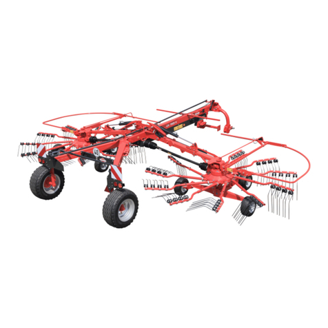
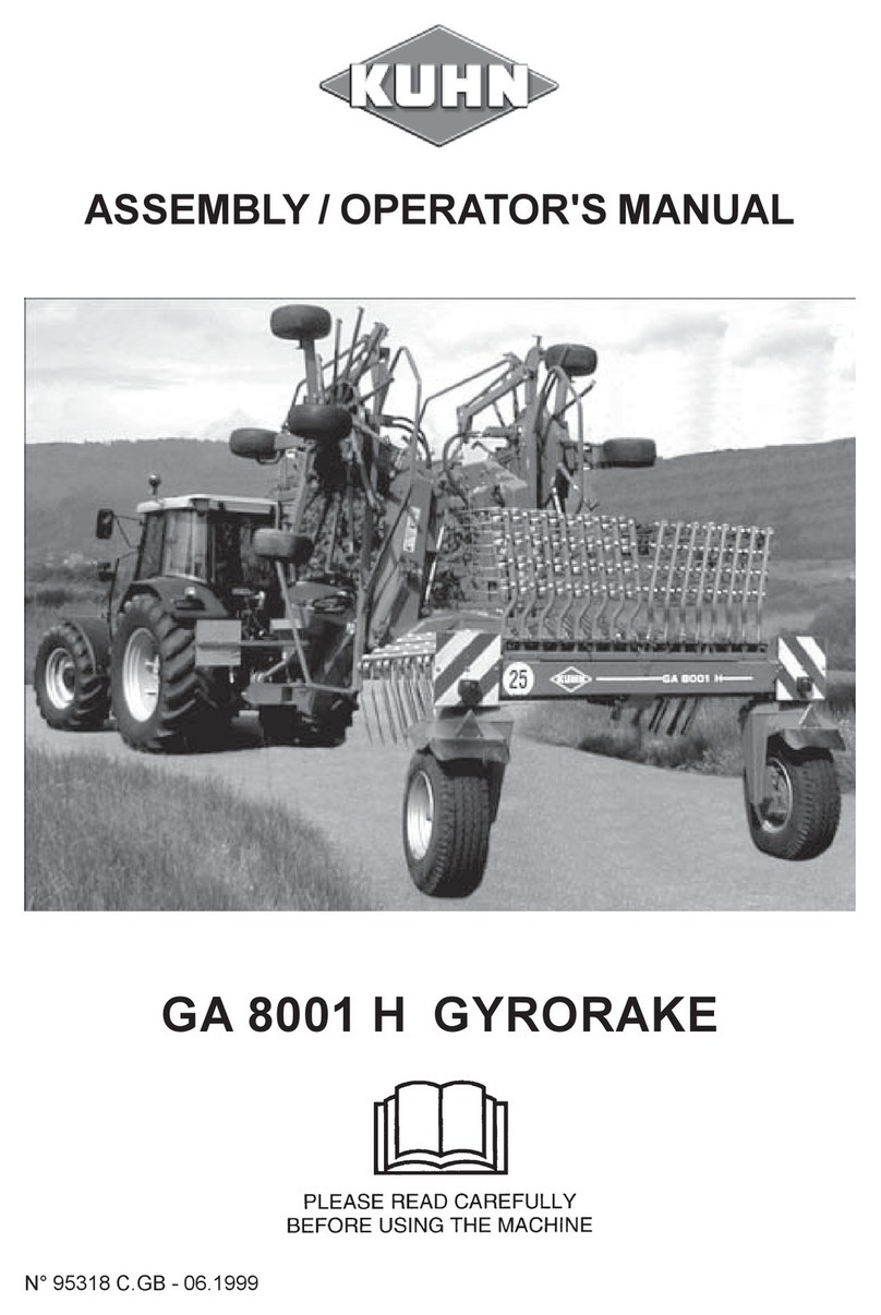
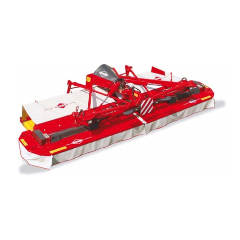
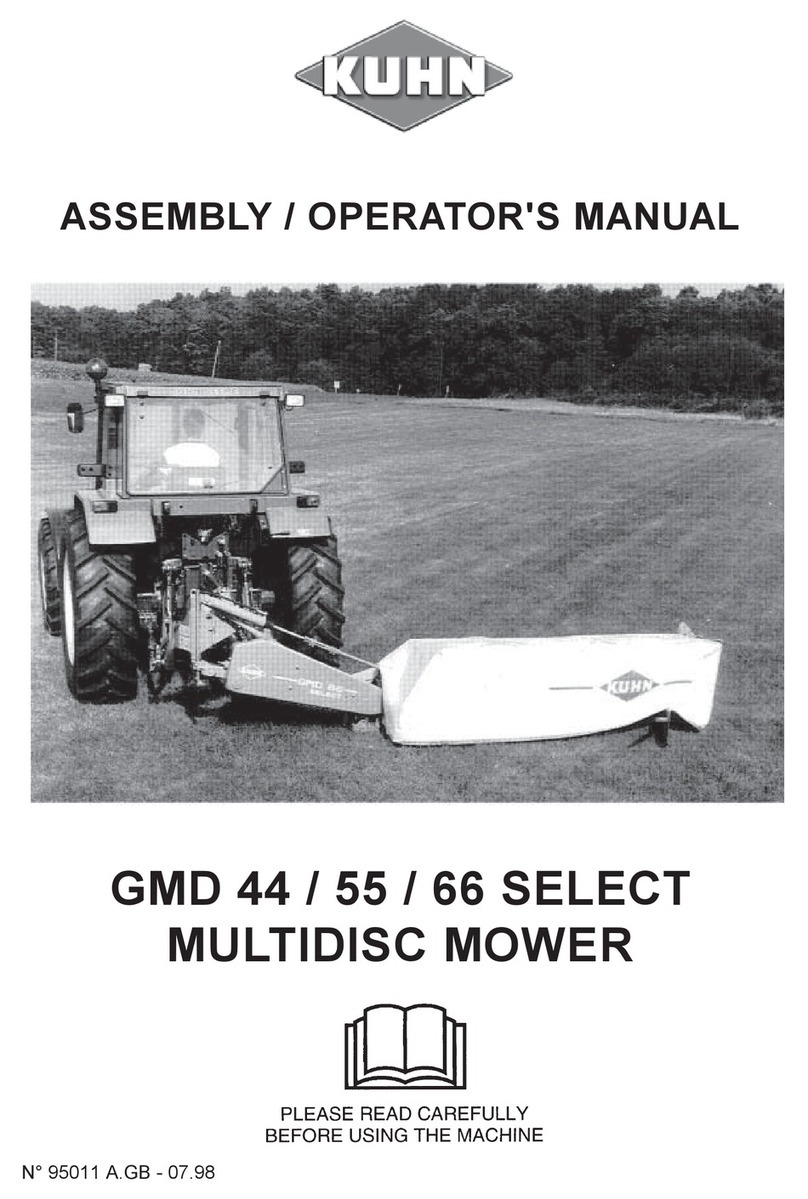
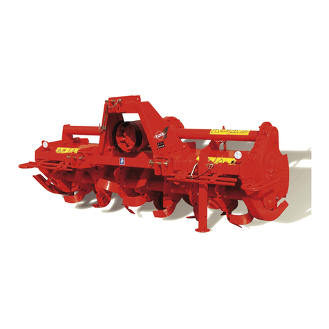
KUHN GA 3501 Super User manual

ASSEMBLY / OPERATOR'S MANUAL
GA 3501 SUPER
GYRORAKE
N° 95305 A.GB - 03.96

DEAR OWNER,
In buying a KUHN machine you have chosen wisely. Into it have gone yea s of thought,
esea ch and imp ovements. You will find, as have thousands of owne s all ove the wo ld, that
you have the best that enginee ing skill and actual field testing can p oduce. You have
pu chased a dependable machine, but only by p ope ca e and ope ation can you expect to
eceive the pe fo mance and long se vice built into it.
This manual contains all the necessa y info mation fo you to eceive full efficiency f om you
machine. The pe fo mance you get f om this machine is la gely dependant upon how well you
ead and unde stand this manual and apply this knowledge. Please DO NOT ASSUME THAT
YOU KNOW HOW TO OPERATE AND MAINTAIN YOUR MACHINE befo e eading this
manual ca efully. KEEP THIS MANUAL AVAILABLE FOR REFERENCE.
You KUHN deale will inst uct you on the gene al ope ation of you machine. He is inte ested
that you get the best pe fo mance possible and will be glad to answe any special questions
that may a ise ega ding the ope ation of the KUHN machine.
You KUHN deale can offe a complete line of genuine KUHN se vice pa ts.
These pa ts a e manufactu ed and ca efully inspected in the same facto y that builds the
machine to assu e high quality and accu ate fitting of any necessa y eplacements.
When o de ing se vice pa ts it is impo tant that you indicate the type of machine conce ned
and its se ial numbe .
Fo this eason please complete the model identification plate diag am below with the equi ed
info mation. This will p ovide you with an easy efe ence fo futu e se vice pa ts o de s.
ABOUT IMPROVEMENTS
KUHN is continually st iving to imp ove its p oducts and, the efo e, ese ves the ight to make
imp ovements o changes when it becomes p actical to do so, without incu ing any
obligations to make changes o additions to the equipment sold p eviously.

- 1 -
CONTENTS
Page
Safety 2
Safety decals 7
Technical specifications 9
Assembly 10
Attachment : Fitting to the tractor 14
Fitting TO shaft 18
Working position and adjustments 19
Operation 21
Forward speed 22
Transport position 23
arking the machine 24
Lubrication 24
Optional accessories 25
Trouble shooting guide 26
Conditions of limited warranty 28
Copyright 1996 KUHN S.A.

- 2 -
SAFETY ADVICE
The above symbol is used throughout this manual every time recommendations are made concerning your safety,
the safety of others, or the good operation of the machine.
These recommendations must be made known to all machine operators.
DESIGNATED USE OF THE MACHINE
The GA 3501 SUPER Gyrorake must only be used for the work for which it has been designed : raking on the
ground and forming windrows of pre-mowed fodder and straw.
The manufacturer is not held liable for any damage resulting from machine applications other than those specified
by the manufacturer.
Any use other than the designated operation is at the risk and responsibility of the operator.
Designated use of the machine also means :
- following operation, maintenance and repair recommendations given by the manufacturer ;
- using only genuine spare parts, equipment and accessories as designated by the manufacturer.
The GA 3501 SUPER Gyrorake must only be operated, maintained and repaired by competent persons who
are familiar with machine specifications and operation and are aware of any danger involved.
The operator must imperatively respect current legislation concerning :
- accident prevention,
- work safety,
- public traffic circulation.
All safety advice indicated on the machine must be strictly observed.
The manufacturer is not held liable for any damage resulting from machine modifications carried out by the
operator himself or by a third party without previous written agreement from the manufacturer.

- 3 -
GENERAL SAFETY RECOMMENDATIONS
Before operating the machine, always ensure that tractor and machine are in accordance with work safety and
road traffic regulations.
BASIC PRINCIPLES
1. In addition to the recommendations given in this manual, legislation on work safety and accident prevention
must also be respected.
2. Advice is indicated on the machine, specifying safety recommendations in order to prevent accidents.
3. Before travelling on public roads, the operator must ensure that the machine conforms to road traffic
regulations.
4. Before starting work, the operator must be familiar with all machine controls, handling devices and their
functions. Once at work, it is too late to do so !
5. Do not wear loose clothing which could become caught up in moving elements.
6. Use a tractor equipped with a safety cab. Keep windows and roof hatch closed for reduced sound level while
operating the TO driven implement.
7. Before starting up the machine and beginning work, check the surrounding area (beware of children !). Make
sure there is sufficient visibility.
Keep all people and animals away from the danger zone of the machine (risk of projection !)
8. Carrying people or animals on the machine when working or in transport is strictly forbidden.
9. Machine must only be attached to tractor using means provided and in accordance with current safety
standards.
10. When attaching or removing the machine, place the parking stand into the corresponding position.
11. Special care should be taken when attaching or removing the machine from the tractor.
12. Before attaching the machine, ensure that the front tractor axle is sufficiently ballasted.
Ballast is to be placed on the supports provided in accordance with instructions of the tractor manufacturer.
13. Do not surpass the maximum axle load or the overall transport weight as prescribed by the tractor manufacturer.
14. Do not exceed the maximum transport width authorized by road traffic regulations.
15. Before transporting the machine on public roads, ensure that all legally required guards and indicators (lights,
reflectors ...) are in place and in good operation.
16. All operating controls (cords, cables, rods...) must be positioned so that they cannot be set off accidently,
risking accident or damage.

- 4 -
17. Before travelling on public roads, put the machine into its transport position as instructed in this operators
manual.
18. Never leave the tractor seat while the machine is operating.
19. Drive speed must be adapted to ground conditions as well as to roads and paths.
Always avoid abrupt changes of direction.
20. recision steering, tractor adherence, road holding and efficient braking are influenced by the type of
implement, weight, ballast of front axle, ground or road conditions. It is therefore of utmost importance to be
cautious in every given situation.
21. Be particularly cautious when turning corners, paying attention to machine overhang, length, height and weight.
22. Before operating the machine, ensure that all safety guards are firmly in place and in good condition. If worn
or damaged, replace immediately.
23. Before operating the machine, check the tightness of all nuts and bolts, particularly on fixing elements (blades,
tines, knives, spades ...)
24. Keep clear of the machine operating area.
25. WARNING ! Danger of crushing and shearing can exist when components are operated by hydraulic or
pneumatic controls.
26. Before leaving the tractor or before adjusting, maintaining or repairing the machine, turn off the engine, remove
the ignition key and wait until all moving parts have come to a complete stop.
27. Do not stand between the tractor and the machine unless the hand brake is tight and/or stops have been placed
under the wheels.
28. Before any adjustments, maintenance or repairs are carried out, ensure that the machine cannot be started
up accidentally.
ATTACHMENT
1. When attaching or removing the machine from the tractor, position hydraulic lift control lever in such a way that
it cannot be set off accidentally.
2. When attaching the machine to the tractor hydraulic linkage, ensure that diameter of the link pins corresponds
to the diameter of the ball joints.
3. WARNING ! Danger of crushing and shearing can exist in the lifting zone of the tractor hydraulic linkage !
4. Do not stand between the tractor and the machine when operating the outer control lever of the lift mechanism.
5. In transport, the machine lift mechanism should be stabilized by tractor tie rods to avoid floatation and side
shifting.
6. When transporting machine ensure that it can not be lowered accidentally.

- 5 -
POWER TAKE-OFF
1. Use only the TO shaft supplied with the machine or recommended by the manufacturer.
2. TO guards must always be in place and in good condition.
3. Check for correct TO overlap when at work and in transport.
4. Before attaching or removing the TO shaft, disengage TO shaft, turn off engine and remove ignition key.
5. If a primary TO shaft is equipped with a slip clutch or a free wheel, these must be fitted on the machine TO.
6. Ensure that TO shaft is always correctly fitted and locked into place.
7. Make sure guards are correctly in place and secured with the safety chains provided.
8. Before engaging TO, ensure that TO speed and direction are in accordance with manufacturer's
recommendations.
9. Before engaging TO, keep all people and animals clear from the machine.
10. Never engage TO shaft when tractor engine is turned off.
11. Never surpass the TO angle recommended by the manufacturer.
12. WARNING ! Rotating elements can continue turning momentarily after TO is disengaged. Keep clear until
all rotating elements are at a standstill.
13. When removing the machine, place TO shaft on the supports provided.
14. Fit the safety cap on tractor TO.
15. Replace any worn or damaged TO guards immediately.
MAINTENANCE

- 6 -
1. Before checking for any machine malfunction and before adjusting, maintaining or repairing the machine,
disengage TO, turn off engine and remove ignition key.
2. Check tightness of nuts and bolts regularly. Retighten if necessary.
3. If the machine is raised, prop it up in a stable position before carrying out any maintenance work.
4. When replacing a working part, wear protection gloves and only use standardized tools.
5. It is forbidden to discard any oil, grease or filters. These must be given to waste disposal organisations to
protect the environment.
6. Disconnect power source before any work is done to the electric system.
7. Check safety guards regularly, particularly those that are subject to wear. Replace immediately if damaged.
8. Spare parts used must be in accordance with specifications and standards as defined by the manufacturer.
Use only genuine KUHN parts !
9. Before any electric welding is carried out on tractor or attached machine, disconnect generator and battery
terminals.
10. Repairs on elements under pressure or tension (springs, accumulators etc...) must only be carried out by
competent persons with standardized equipment.
SPECIAL SAFETY RECOMMENDATIONS
ATTENTION ! When on a public highway the machine must always be mounted behind the tractor.
TIRES
1. Before any work is performed on the wheels, ensure that the machine rests on the ground and is perfectly stable
so that it cannot move accidentally (put wedges in place).
2. Assembly, disassembly and repair of wheels and tires must only be carried out by competent persons who are
equipped with standardized tools.
3. Check tire pressure regularly !
Respect manufacturers recommendations on tire pressure.

- 7 -
SAFETY DECALS
THE FOLLOWING SAFETY ICTORIALS HAVE BEEN LACED ON YOUR MACHINE IN THE AREAS
INDICATED. THEY ARE INTENDED FOR YOUR ERSONAL SAFETY AND FOR THE SAFETY OF
THE EO LE WORKING WITH YOU. THE TEXT SHOWN ON THEM GIVES THEIR RECISE
MEANING. ENSURE THAT THESE ICTORIALS ARE ALWAYS LEGIBLE. IF THEY ARE NOT,
RE LACE THEM.

- 8 -

- 9 -
TECHNICAL SPECIFICATIONS
Attachme t : To the front and/or to the rear of the tractor with an A frame type quick hitch (ACCORD type)
and/or a Cat. II 3-point linkage.
Working width with single windrow 3.5 m (116")
Transport width 2 m (67")
Forward speed up to 15 km/h (up to 9 mph)
Work rate per hour up to 3.5 ha (up to 9 acres)
ower requirement 15 kW (20 hp)
Total weight 500 kg (1102 lbs)
TO shaft with torque limiter
Tyres 15 x 6.00 - 6
Tyre pressure 2 bars/29 psi
Number of tine arms 10
Number of tines 30
Special characteristics of the GA 3501 S :
- Undercarriage with 4 wheels positioned triangularly and a central pivoting rotor to match irregular terrain.
- The windrow is always formed to the right when looking in the direction of travel, whether the machine is pushed
or pulled.
- Tine arms may be disconnected and safety guards folded back to facilitate transport and storage.

- 10 -
FITTING INSTRUCTIONS
To facilitate shipping, the GA 3501 S is delivered with a certain number of disassembled parts. To assemble
these parts, proceed as follows.
1. Fitting tine arms an tines
Fit tine arms (E) to supports (S) and secure using linch
pins (U) (fig. 3).
Connect the small loop of safety strap (X) to linch pin
(U), then connect the large safety strap loop to the hole
(A) of bracket (W) on tine arm (E) (fig. 3).
Fit the supports (S) with tine arms on the oscillating
shafts (L) using roll pins (V) (dia. 12 x 55 and 7 x 55) (fig.
3).
ATTENTION : Make sure slots of roll pins are orien-
tated opposite to one another and in the direction of
main effort.
Clean and regularly apply a Never-
Seize compound to the removable por-
tion of the tine arms (E) (fig. 3 and also
page 23).
Ensure that the tine arms (E) are positioned so that the curved portion is facing the front as seen in the direction
of rotation (see arrows fig. 2 and 3).
Attach tines (F) underneath tine arms (E) so that their fingers are slanting away from the direction of rotation (see
arrows fig. 2 and 3). Then secure to the arms by using screw (B) (M12x75), self-locking nut (G) (M12), washer (C)
(dia. 13x35x5), spring washer (H) and tine bracket (D).
Make sure that all parts are assembled correctly as shown in fig. 3

- 11 -
2. Fitting PTO shaft support
Attach preassembled TO shaft support (A) to frame
(D) with 2 screws (E) (M 12 x 25), 2 flat washers (F) (dia.
14 x 27 x 2.5 mm) and 2 self-locking nuts (G) (M12) (fig.
4).
The lining up of support (A) with the tractor TO shaft
is carried out after loosening the screws (E). Tighten
the screws (E) after adjustment.
3. Fitting safety guar s
NOTE : All guard joints must be greased with a Never-Seize compound before assembling.
Attach the rear right guards (D) (identified by the handle) and the left guards (G) on the 2 connecting rods (A) of the
safety guard support (photo 5) with 2 flat washers (N) (dia. 13x45x5 mm) and 2 hexagonal screws (H) (M12x25), taking
care to correctly place O-rings (T) (dia. 23.4x3.6 mm) (fig. 6).
Lock rear guards in the open position (photo 5) with spring cotter (U) (dia. 4 mm) (photo 7). Attach the large safety
strap loop (V) to axle (Y), as shown in photo 7.

- 12 -
Mount right (E) and left (F) front guards (identified by
decals) on each side of frame ( ) (photo 5) with 2 long
axles (L), 2 hexagonal screws (I) (M12 x 100) and 2 self-
locking nuts (J) (M12), being careful to correctly place
O-rings (O) (dia. 18.3 x 3.6 mm) (fig. 8).
Next assemble the right (K) and left (M) intermediate guards (identified by the locking lugs) onto the front guards
(E) and (F) on one end and onto the rear guards (D) and (G) on the other end (photo 5). Assemble with 4 short axles,
4 hexagonal screws (M12 x 75), 4 self-locking nuts (M12) and 8 O-rings (dia. 18.3 x 3.6 mm) as shown in fig. 8, but
do ot fully tighte the screws at this stage. At the same time attach the red reflector sets (R) at the rear and
the white reflector sets (S) to the front of the machine (photo 5) (when looking in the forward direction when the
machine is attached to the rear of the tractor).
lace guards in the transport position (photo 9) and lock them into place with spring cotter (U) (photo 10). osition
reflector sets so that the red reflectors (R) are turned toward the rear and the white reflector sets toward the front
(photo 9).
Now tighte the 4 i termediate guard mou ti g screws.

- 13 -
4. Fitting swath screen (photo 11)
Slide swath screen support (A) underneath clamp (C)
and tighten handle ( ).
Fit canvas (D) to support (A) in one of the vertical
adjustment positions using 2 hexagonal screws (H)
(M10 x 30) 2 self-locking nuts (M10) and 2 plain wash-
ers (dia. 11 x 24 x 4). Fit these washers between
canvas (D) and support (A).

- 14 -
FITTING TO THE TRACTOR
1. ATTACHMENT
The GA 3501 SUPER can be attached to the front
and to the rear of the tractor with an A frame attachment
(ACCORD type) and a Cat. II 3-point hitch attachment.
a ) A frame attachme t
Lower the tractor hydraulic lift and attach the rake
(photo 12).
NOTE :
Check that stop (3) of the triangular frame (A) is ad-
justed correctly. For good operation this stop must be
positioned against latch (4) so that latch is still free to
pivot when pulling lever (5).
If this is not the case, detach machine from the tractor
and proceed as follows :
- Untighten flush screw (2) so that stop (3) is free to
slide.
- Untighten lock nut of adjusting screw (1).
- Attach machine to the tractor.
- Rotate adjusting screw (1) until stop (3) contacts
latch (4).
- Check that latch (4) is free to operate by pulling lever
(5). If operation is difficult untighten screw (1) half a
turn.
- Detach machine from tractor.
- Tighten lock nut of adjusting screw (1) and tighten
flush screw (2).
Regularly check that stop (3) is adjusted correctly,
especially each time the machine is adapted to a new
triangular frame (A). Readjust if necessary.
b) Cat. II 3-poi t hitch adjustme t
To fit attachment parts proceed as follows :
- osition hitching frame (H) into its housing and se-
cure with spindle (I) and spring cotter (G) (fig. 14 and
photo 15).
- Slide lower hitch bar (K) in place so that spacer (E)
faces the attachment plate having 2 holes (O and O)
(fig. 14).
NOTE :When front mounting the implement to a trac-
tor with a wide wheel track the machine can be
offset in an oblique position preventing the
tractor wheels from running over the swath
and pressing it down.
The oblique position is obtained by sliding
lower hitch bar (K) through hole (O)(photo
15A). In all other cases hitch bar (K) should be
inserted through hole (O) (photo 15).

- 15 -
Attach the tractor lower link arms (A) to the hitch bar (K) and attach top link (C) to the corresponding clevis (photo
15).
Stabilize the lower link arms from side to side movement using the means provided (check chains, turnbuckles,
etc.). Fold up parking stand (D) in the horizontal position (photo 15).
Unlatch parking stand (D) by pulling it down, then fold it up in the horizontal position (photos 15 and 15A).
2. PTO DRIVE
The GA 3501 SUPER is supplied with a reversible two-speed gearbox allowing the machine to be driven
at 540 rpm and 1000 rpm in any TO direction of rotation.
The different possible combinations are given as follows :
- First situation (fig. 16 an photo 17)
Machine attached to the front or to the rear of the tractor.
Tractor TO speed : 540 rpm
Direction of tractor TO rotation : clockwise (when facing the TO end)
The machine has been factory set for this combination : no gearbox adjustment is required.

- 16 -
- Secon situation (fig. 18 an photo 19)
Machine attached to the front of the tractor.
Tractor TO speed : 540 rpm
Direction of tractor TO rotation : cou ter-clockwise (when facing the TO end)
In this case, the 2-speed gearbox is not to be used.
roceed as follows to detach gearbox :
- Take off guard cone (H) and its support by unscrewing the 2 wing nuts (E) (photo 17).
- Remove linch pin (G) (photo 17) and detach gearbox.
- Bolt guard cone assembly (H) on the 2 welded nuts (S) (photo 17) with the 2 wing nuts (E) (photo 19).
- Thir situation (fig. 20)
Machine attached to the front or the rear of tractor
Tractor TO speed : 1000 rpm
Direction of tractor TO rotation : clockwise (when
facing the TO end)
- Take off gearbox after first removing linch pin (G)
(photo 17).
- Remove the gearbox input shaft and reinstall it in the
other splined hub (see fig. 20).
- Slide gearbox back in place.

- 17 -
Summary chart
- Fourth situation (fig. 21)
Machine attached to the front of the tractor
Tractor TO speed : 1000 rpm
Direction of tractor TO rotation : cou ter-clockwise
(when facing TO end).
- Detach gearbox after first removing linch pin (G)
(photo 17).
- Remove guard cone (H) and its support by
unscrewing the 2 wing nuts (E) (photo 17).
- Remove input shaft.
- Rotate gearbox 180° around axis XX (see fig. 21).
- Reinstall input shaft in its splined hub (see fig. 21).
- Reattach guard cone (H) on gearbox with the 2 wing
nuts (E).
- Slide gearbox in place and secure with linch pin (G).
I all 4 situatio s, e sure that protective cover (P) is always mou ted i side guard
co e (H) a d secured with the wi g uts (J) (photos 17 a d 19) to avoid risk of serious
accide ts.
Clockwise Counter-clockwise
Front 540 figure 16 figure 18
Rear 540 figure 16 -
Front 1000 figure 20 figure 21
Rear 1000 figure 20 -
Tractor TO direction of rotation
Machine attachment Tractor TO speed (rpm)

- 18 -
PTO
lace the TO shaft in its support and connect it to the machine input shaft and to the tractor TO (the outside TO
shaft guard nearest the tractor). The TO shaft must always be located inside its support during work.
Make sure TO shaft length is correct :
1) When the TO shaft is in its maximum extended position, a minimum tube overlap of 300 mm (12") must be
maintained.
2) When the TO shaft is in its maximum overlap position (retracted), tubes must not butt against the yokes. As
a safety measure a clearance of at least 2 cm (0.8") must be maintained. If this is not the case, shorten the two
transmission tubes and the two guard tubes by the same length (photo A and B). Bevel and clean the tubes
(photo C) and grease the inside of the outer tube (photo D).
3) Never operate the TO at too great an angle (30° maximum).
These recommendations and adjustments must be respected to avoid damage or premature wear
of the TO shaft.
Before operating the machine, double check that the gearbox setting matches the selected tractor
TO speed and TO direction of rotation.
To avoid accidents which could be serious, make sure that the guards are always correctly in place
and secured with the safety chains provided. Damaged guards should be replaced immediately.
Table of contents
Other KUHN Farm Equipment manuals

KUHN
KUHN HAYBOB 360 User manual

KUHN
KUHN MOUNTED MINOTOR 3050 User manual

KUHN
KUHN Hector 3000 User manual

KUHN
KUHN GA 4311 GM User manual

KUHN
KUHN GF 5801 MH User manual

KUHN
KUHN KNM User manual

KUHN
KUHN FC 4000 RG User manual

KUHN
KUHN GF 5001 MH User manual

KUHN
KUHN GMD702F User manual

KUHN
KUHN GA 4511 GM User manual
Popular Farm Equipment manuals by other brands

Poettinger
Poettinger EUROTOP 1251 A Operator's manual

Kunz
Kunz AcrEase H60B owner's manual

Tar River Implements
Tar River Implements PRZ-3100 Operator's manual

BERARDINUCCI
BERARDINUCCI TORNADO Operating and maintenance manual

COSMO Bully
COSMO Bully UL Series Operator and parts manual

Amazone
Amazone GreenDrill 501-H Translation of the original operating instructions