9
Specications
KE7200
Connections RJ-45 socket;
Adapter: RJ-45 to coaxial cable, RJ-11 to banana plug, including crocodile clips for banana plug
Cable Test
(Ethernet cable,
coaxial cable,
telecommunica-
tions cable)
Detection of reversed connections, short circuits, interruptions, split pairs (as of 2 m), testing of the data line
assignment with pin and pair assignment (wire mapping)
Clear graphical display for fast error identication
TDR function: Measurement of individual wire lengths from 2 m to 200 m
Cable database: 15 wiring versions predened for cable test and creation of own denitions possible as of 2
wires, including Pronet;
16 cable types predened with VF for TDR length measurement and creation of own cable types possible
Check for external voltage before test start
Network Tests
(Ethernet cable)
IP test
• Connection to the network via DHCP or with static IP (own IP and MAC address congurable)
• List of active network subscribers with name, IP address and MAC address
• Detection of network speed 10/100/1000 Mbit
Ping test
• Targeted ping of individual addresses and simultaneous ping stress test
• Ping frame sizes adjustable from 32-1024 bytes
• Display of ping results (received/lost) and response times (min./max./average)
Power over
Ethernet Test
(Ethernet cable)
Activation of PoE/PoE+/PoE++/LTPoE functions
Measurement of the voltage in V and determination of the power (up to 90 W) according to IEEE802.3af/at/bt
Port Finder
Function
(Ethernet cable)
Link blink function for identifying ports on routers/switches/hubs:
Transmission of an NLP signal that switches the link LED associated with the port on and off in the same cycle on
the most common hubs, switches, or routers.
Tone Mode
(telecommunica-
tions cable)
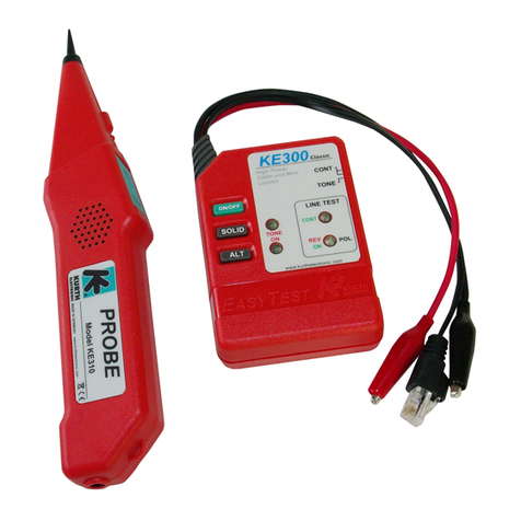
Emission of a search tone signal; using the probe search signal receiver, the associated network port can be
clearly identied on the patch panel, etc.
4 search frequencies available for selection: 1000 Hz; 880/1000 Hz; 2600 Hz, and 2600/1900 Hz
Compatible probes: P310 (D130B), P410 (D140B)
Branch
Detection
(coaxial cable,
telecommunica-
tions cable)
Precise localization of branches / stub lines (bridge taps) in telecommunications networks in buildings. Determines
existence of and distance to the branch / stub line.
Can be purchased as an option.
Additional
Functions
• Memory function for 14,000 entries
• Self-test
External Voltage
Protection
60 V DC
Housing Stable, impact-resistant ABS housing with fall protector
Display Illuminated display, adjustable time for display backlighting
Power Supply 4× 1.5 V (AA, LR6, alkaline/mignon) batteries,
with the operating period depending on the test type, the display backlighting duration, and the battery type and
condition
Automatic device switch-off (time adjustable)
Dimensions 195 × 100 mm
Weight 380 g (without batteries)
Menu Languages German, English
Operation
Environment
Working temperature 0 °C … +50 °C
Storage temperature –25 °C … +75 °C
Humidity 90%, non-condensing


