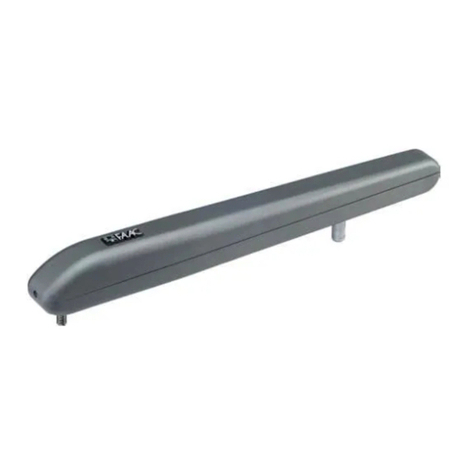
FAAC 412 Compact User manual

412
412
C
E
R
M
E
T
A
Z
I
E
N
D
A
C
E
R
T
I
F
I
C
A
T
A
UNI EN ISO 9001-085
para la naturaleza
100% papel reciclado
ist umweltfreundlich
100% Altpapier
pour la nature
papier recyclé 100%
for nature
recycled paper 100%
carta riciclata 100%
per la natura

Timbro del Rivenditore:/Distributor’s Stamp:/Timbre de l’Agent:/ Fachhändlerstempel:/Sello del Revendedor:
FAAC S.p.A.
Via Benini, 1
40069 Zola Predosa (BO) - ITALIA
Tel.:051/61724
Fax:051/758518
FAAC per la natura
• La presente istruzione è realizzata al 100% in carta riciclata.
• Non disperdete nell'ambiente gli imballaggi dei componenti dell'automazione bensì selezionate
i vari materiali (es. cartone, polistirolo) secondo prescrizioni locali per lo smaltimento rifiuti e le
norme vigenti.
FAAC for the environment
• The present manual is produced in 100% recycled paper
• Respecttheenvironment.Disposeofeachtypeofproduct packaging material (card, polystyrene)
in accordance with the provisions for waste disposal as specified in the country of installation.
FAAC der Umwelt zuliebe
• Vorliegende Anleitungen sind auf 100% Altpapier gedruckt.
• Verpackungsstoffe der Antriebskomponenten (z.B. Pappe, Styropor) nach den einschlägigen
Normen der Abfallwirtschaft sortenrein sammeln.
FAAC écologique
• La présente notice a été réalisée 100% avec du papier recyclé.
• Ne pas jeter dans la nature les emballages des composants de l’automatisme, mais sélectionner
les différents matériaux (ex.: carton, polystyrène) selon la législation locale pour l’élimination des
déchets et les normes en vigueur.
FAAC por la naturaleza.
• El presente manual de instrucciones se ha realizado, al 100%, en papel reciclado.
• Los materiales utilizados para el embalaje de las distintas partes del sistema automático (cartón,
poliestireno)no deben tirarse al medio ambiente,sinoseleccionarse conforme a las prescripciones
locales y las normas vigentes para el desecho de residuos sólidos.
732238 - Rev.C
para la naturaleza
100% papel reciclado
ist umweltfreundlich
100% Altpapier
pour la nature
papier recyclé 100%
for nature
recycled paper 100%
carta riciclata 100%
per la natura
Le descrizioni e le illustrazioni del presente manuale non sono impegnative. La FAAC si riserva il diritto,
lasciando inalterate le caratteristiche essenziali dell’apparecchiatura, di apportare in qualunque
momento e senza impegnarsi ad aggiornare la presente pubblicazione,le modifiche che essa ritiene
convenienti per miglioramenti tecnici o per qualsiasi altra esigenza di carattere costruttivo o
commerciale.
The descriptions and illustrations contained in the present manual are not binding. FAAC reserves the
right, whilst leaving the main features of the equipments unaltered, to undertake any modifications it
holds necessary for either technical or commercial reasons, at any time and without revising the
present publication.
Les descriptions et les illustrations du présent manuel sont fournies à titre indicatif. FAAC se réserve le
droit d’apporter à tout moment les modifications qu’elle jugera utiles sur ce produit tout en conservant
les caractéristiques essentielles, sans devoir pour autant mettre à jour cette publication.
Die Beschreibungen und Abbildungen in vorliegendem Handbuch sind unverbindlich. FAAC behält
sich das Recht vor, ohne die wesentlichen Eigenschaften dieses Gerätes zu verändern und ohne
Verbindlichkeiten in Bezug auf die Neufassung der vorliegenden Anleitungen, technisch bzw.
konstruktiv/kommerziell bedingte Verbesserungen vorzunehmen.
Las descripciones y las ilustraciones de este manual no comportan compromiso alguno. FAAC se
reserva el derecho,dejando inmutadas las características esenciales de los aparatos, de aportar,en
cualquier momento y sin comprometerse a poner al día la presente publicación, todas las
modificaciones que considere oportunas para el perfeccionamiento técnico o para cualquier otro
tipo de exigencia de carácter constructivo o comercial.

1
ITALIANOITALIANO
1) ATTENZIONE!Èimportante per la sicurezzadelle persone seguireatten-
tamente tutta l’istruzione. Una errata installazione o un errato uso del
prodotto può portare a gravi danni alle persone.
2) Leggere attentamente le istruzioni prima di iniziare l’installazione del
prodotto.
3) I materiali dell’imballaggio (plastica,polistirolo,ecc.) non devono es-
sere lasciati alla portata dei bambini in quanto potenziali fonti di
pericolo.
4) Conservare le istruzioni per riferimenti futuri.
5) Questo prodotto è stato progettato e costruito esclusivamente per
l’utilizzo indicato in questa documentazione. Qualsiasi altro utilizzo non
espressamente indicato potrebbe pregiudicare l’integrità del prodot-
to e/o rappresentare fonte di pericolo.
6) FAAC declina qualsiasi responsabilità derivata dall’uso improprio o
diverso da quello per cui l’automatismo è destinato.
7) Non installare l’apparecchio in atmosfera esplosiva: la presenza di gas
o fumi infiammabili costituisce un grave pericolo per la sicurezza.
8) Gli elementi costruttivi meccanici devono essere in accordo con
quanto stabilito dalle Normative UNI8612, CEN pr EN 12604 e CEN pr
EN 12605.
Per i Paesi extra-CEE, oltre ai riferimenti normativi nazionali, per ottene-
re un livello di sicurezza adeguato, devono essere seguite le Norme
sopra riportate.
9) FAAC non è responsabile dell’inosservanza della Buona Tecnica nella
costruzione delle chiusure da motorizzare, nonchè delle deformazioni
che dovessero intervenire nell’utilizzo.
10) L’installazione deve essere effettuata nell’osservanza delle Norme
UNI8612, CEN pr EN 12453 e CEN pr EN 12635.
Il livello di sicurezza dell’automazione deve essere C+D.
11) Prima di effettuare qualsiasi intervento sull’impianto, togliere l’alimen-
tazione elettrica.
12) Prevedere sulla rete di alimentazione dell’automazione un interruttore
onnipolare con distanza d’apertura dei contatti uguale o superiore a
3 mm. È consigliabile l’uso di un magnetotermico da 6A con interruzio-
ne onnipolare.
DICHIARAZIONE CE DI CONFORMITÁ PER MACCHINE
(DIRETTIVA 89/392/CEE, ALLEGATO II, PARTE B)
Fabbricante: FAAC S.p.A.
Indirizzo: Via Benini, 1 - 40069 Zola Predosa BOLOGNA - ITALIA
Dichiara che: L'operatore mod. 412,
• è costruito per essere incorporato in una macchina o per essere assemblato con altri macchinari per costituire
una macchina ai sensi della Direttiva 89/392/CEE, e successive modifiche 91/368/CEE, 93/44/CEE, 93/68/CEE;
• è conforme ai requisiti essenziali di sicurezza delle seguenti altre direttive CEE:
73/23/CEE e successiva modifica 93/68/CEE.
89/336/CEE e successiva modifica 92/31/CEE e 93/68/CEE
e inoltre dichiara che non è consentito mettere in servizio il macchinario fino a che la macchina in cui sarà
incorporato o di cui diverrà componente sia stata identificata e ne sia stata dichiarata la conformità alle
condizioni della Direttiva 89/392/CEE e successive modifiche trasposta nella legislazione nazionale dal DPR n°
459 del 24 luglio 1996.
Bologna, 01,gennaio,1999
L’Amministratore Delegato
A. Bassi
13) Verificare che a monte dell’impianto vi sia un interruttore differenziale
con soglia da 0,03 A.
14) Verificare che l’impianto di terra sia realizzato a regola d’arte e
collegarvi le parti metalliche della chiusura. Collegare inoltre a terra
il filo Giallo/Verde dell’automatismo.
15) L’automazione dispone diuna sicurezza intrinseca antischiacciamento
costituita da un controllo di coppia che deve comunque essere
sempre accompagnato ad altri dispositivi di sicurezza.
16) I dispositivi di sicurezza (Es.: fotocellule,coste sensibili,ecc...) permet-
tono di proteggere eventuali aree di pericolo da Rischi meccanici di
movimento, come ad Es. schiacciamento, convogliamento,
cesoiamento.
17) Per ogni impianto è indispensabile l’utilizzo di almeno una segnalazio-
ne luminosa (es: FAAC LAMP MINILAMP, ecc.) nonchè di un cartello di
segnalazione fissato adeguatamente sulla struttura dell’infisso, oltre
ai dispositivi citati al punto “16”.
18) FAAC declina ogni responsabilità ai fini della sicurezza e del buon
funzionamento dell’automazione, in caso vengano utilizzati compo-
nenti dell’impianto non di produzione FAAC.
19) Per la manutenzione utilizzare esclusivamente parti originali FAAC.
20) Non eseguire alcuna modifica sui componenti facenti parte il sistema
d’automazione.
21) L’installatore deve fornire tutte le informazioni relative al funziona-
mento manuale del sistema in caso di emergenza e consegnare
all’Utente utilizzatore dell’impianto il libretto d’avvertenze allegato al
prodotto.
22) Non permettere ai bambini o persone di sostare nelle vicinanze del
prodotto durante il funzionamento.
23) Tenere fuori dalla portata dei bambini radiocomandi o qualsiasi altro
datore di impulso, per evitare che l’automazione possa essere
azionata involontariamente.
24) L’Utente utilizzatore deve astenersi da qualsiasi tentativo di riparazio-
ne o d’intervento diretto e rivolgersi solo a personale qualificato.
25) Tutto quello che non è previsto espressamente in queste istruzioni non
è permesso
AVVERTENZE PER L’INSTALLATORE
OBBLIGHI GENERALI PER LA SICUREZZA

2
ITALIANO ITALIANO
Tav. A QUOTE D'INSTALLAZIONE
b
a
zd
80
892
Fig. A
Fig. B
Tabella A: Quote consigliate
Angolo di a b c (*) d (**)
apertura "αα
αα
α" (mm) (mm) (mm) (mm)
90° 145 145 290 100
110° 125 125 290 80
(*) corsa utile dello stelo (**) quota massima
REGOLE GENERALI PER LA DETERMINAZIONE
DELLE QUOTE D’INSTALLAZIONE
Nel caso non sia possibile eseguire le quote indicate
nella tabella A, per determinare misure differenti è
necessario considerare quanto segue:
- per ottenere aperture dell’anta a 90°: a + b = c
- per ottenere aperture dell’anta superiori a 90°: a + b < c
-quote a e b più basse determinano velocità più elevate. Si
raccomanda di rispettare le normative vigenti.
-limitare la differenza delle quote a e b entro 4 cm: differenze
superiori causano variazioni elevate della velocità durante
il moto d’apertura e chiusura.
- per ragioni d’ingombro dell’operatore la quota Z minima è
di 45 mm (fig. A).
Nel caso in cui le dimensioni del pilastro o la posizione della
cerniera non permettano di contenere la quota anella
misura desiderata, è necessario effettuare una nicchia sul
pilastro come da fig. B.
300 mm
150 mm
100 mm
AUTOMAZIONE 412
Le presenti istruzioni sono valide per i seguenti modelli:
Automazione 412 e 412-24V
L’automazione FAAC 412 per cancelli a battente è composta
da due operatori elettromeccanici che trasmettono il
movimento all’anta tramite un sistema a vite senza fine.
Gli operatori garantiscono il blocco meccanico quando il
motore non è in funzione, non è quindi necessario installare
alcuna serratura.
ÜPer ottenere la sicurezza antischiacciamento è necessario
utilizzare apparecchiature elettroniche dotate del dispositi-
vo elettronico di regolazione della coppia.
L'automazione412 èstata progettataecostruitapercontrollare
l’accesso veicolare. Evitare qualsiasi altro diverso utilizzo.
1. DESCRIZIONE E CARATTERISTICHE TECNICHE
Tab. 1 Caratteristiche tecniche "Operatore 412"
412 412-24V
Tensione d’alimentazione 230 V~ 50 Hz 24Vdc
Potenza assorbita (W) 280 70
Corrente assorbita (A) 1,5 3
Motore elettrico 1400 giri/min
Termoprotezione sull’avvolgimento 140 °C /
Condensatore di spunto 8 µF/400V /
Forza di trazione/spinta max (daN) 350 250
Corsa utile dello stelo (mm) 290
Velocità lineare dello stelo (cm/s) 1,6
Temperatura ambiente (°C) -20 v+55 °C
Peso dell’operatore (Kg) 6,5
Grado di protezione IP 44
Frequenza d’utilizzo (cicli/ora) 18 50
Lunghezza massima dell’anta (m) 1,80
a
Gruppo motore
b
Cavo d’alimentazione
c
Vite senza fine
d
Attacco anteriore
e
Attacco posteriore
f
Salvapiega
g
Carter di protezione
Fig. 1
162
5
7
3
4

3
ITALIANOITALIANO
2. PREDISPOSIZIONI ELETTRICHE (Impianto standard)
10) Sbloccare l’operatore e verificare manualmente che il
cancello sia libero di aprirsi completamente fermandosi
sugli arresti meccanici di finecorsa e che il movimento
dell’anta sia regolare e privo di attriti.
11) Saldare definitivamente l’attacco anteriore sull’anta.
Per effettuare tale operazione svincolare momentanea-
mente l’operatore dall’attacco per evitare che scorie di
saldatura possano danneggiarlo.
Fig. 4
Fig. 5
Fig. 6
Fig. 2
aOperatori 412
bFotocellule
cApp. elettronica
dPulsante a chiave
eRicevente
fLampeggiatore
•Per la messa in opera dei cavi elettrici utilizzare adeguati tubi rigidi e/o flessibili.
•Separare sempre i cavi di collegamento degli accessori a bassa tensione da quelli di
alimentazione a 230V ~. Per evitare qualsiasi interferenza utilizzare guaine separate.
Fig. 3
Attenzione: Gli operatori forniti nel kit sono in versione
destra e sinistra. Per una corretta installazione l’operatore
deve essere posizionato come da fig. 3.
3) Sbloccare l’operatore (vedi paragrafo 5).
4) Estrarre completamente lo stelo fino a battuta (fig. 4).
5) Ribloccare l’operatore (vedi paragrafo 6).
6) Ruotare di due giri in senso orario lo stelo dell’operatore
(fig. 4).
7) Montare l’attacco anteriore sullo stelo come da fig. 5.
8) Chiudere l’anta del cancello e, mantenendo l’operatore
perfettamente orizzontale, individuare sull’anta la posizio-
ne dell’attacco anteriore (fig. 6).
9) Fissare provvisoriamente l’attacco anteriore sull’anta tra-
mite due punti di saldatura.
Nota bene: Nel caso la struttura del cancello non permet-
ta un solido fissaggio dell’attacco è necessario intervenire
sulla struttura creando una solida base d’appoggio.
3. INSTALLAZIONE DELL'AUTOMAZIONE
3.1. VERIFICHE PRELIMINARI
Per un corretto funzionamento dell’automazione la struttura
del cancello esistente, o da realizzare, deve presentare i
seguenti requisiti:
• lunghezza massima della singola anta di 1,8 metri;
• struttura delle ante robusta e rigida;
• movimento regolare ed uniforme delle ante, privo di attriti
irregolari durante tutta la corsa;
• buono stato delle cerniere esistenti;
• presenza degli arresti meccanici di finecorsa.
Si raccomanda di effettuare gli eventuali interventi fabbrili
prima d’installare l’automazione.
Lo stato della struttura influenza direttamente l’affidabilità e la
sicurezza dell’automazione.
3.2. INSTALLAZIONE DEGLI OPERATORI
1) Fissare l’attacco posteriore sul pilastro seguendo le indica-
zioni di Tav. A.Modificare, se necessario, la lunghezza
dell’attacco in dotazione.
Attenzione:Per non compromettere il buon funzionamen-
to dell’operatore si raccomanda di rispettare le quote
indicate.
Nel caso di pilastro in ferro saldare accuratamente l'attac-
co direttamente sul pilastro.
Nel caso di pilastro in muratura, incassare opportunamen-
te una piastra a murare (fig. 3). Saldare quindi accurata-
mente l’attacco sulla piastra.
2) Fissare l’operatore all’attacco posteriore tramite la viteria
in dotazione (fig. 3).

4
ITALIANO ITALIANO
Note:
(1) E’ consigliabile ingrassare tutti i perni di fissaggio degli
attacchi.
(2) Nel caso non sia possibile eseguire saldature, le pia-
stre degli attacchi anteriore e posteriore sono predi-
sposte per un’eventuale fissaggio tramite viti e tassel-
li.
12) Predisporre il carter di protezione (fig. 7) ed applicarlo
sull’operatore come da fig. 8.
Nota bene: Fissare il collare di guida del carter sul foro più
lontano dal tappo di chiusura (fig. 7).
13) Eseguire l’installazione del secondo operatore ripetendo
le operazioni sopra indicate.
14) Effettuarei collegamentielettrici all’apparecchiaturaelet-
tronica.
15) Programmare l’apparecchiatura elettronica secondo le
proprie esigenze.
Fig. 9
Fig. 10
SBLOCCA
DESBLOQUEAR
DEBLOQUE
UNLOCK
ENTRIEGELT
BLOCCA
BLOQUEAR
BLOQUE
LOCK
VERRIEGELT
SBLOCCA
DESBLOQUEAR
DEBLOQUE
UNLOCK
ENTRIEGELT
BLOCCA
BLOQUEAR
BLOQUE
LOCK
VERRIEGELT
4. PROVA DELL'AUTOMAZIONE
Terminata l'installazione, applicare l'adesivo di segnalazione
di pericolo sulla parte laterale dell'operatore in modo che
risulti ben visibile (fig. 9).
Procedere alla verifica funzionale accurata dell'automazione
e di tutti gli accessori ad essa collegati.
Consegnare al Cliente la pagina "Guida per l'utente", illustrare
ilcorretto funzionamentoe utilizzodell'operatoreed evidenziare
le zone di potenziale pericolo dell'automazione.
5. FUNZIONAMENTO MANUALE
Nel caso sia necessario azionare manualmente il cancello a
causa di mancanza di corrente o disservizio dell’automazione,
ènecessario togliereil tappodiprotezione edinserire l’apposita
chiave in dotazione nel sistema di sblocco come da fig. 10.
Per sbloccare l’operatore ruotare la chiave nella direzione di
chiusura dell'anta (fig. 10).
Effettuare manualmente la manovra di apertura o chiusura
delle ante.
6. RIPRISTINO DEL FUNZIONAMENTO NORMALE
Per evitare che un impulso involontario possa azionare gli
operatoridurante lamanovra, primadi ribloccaregli operatori,
togliere alimentazione all’impianto.
Per ribloccare l'operatore ruotare la chiave nella direzione
d'apertura dell'anta (fig. 10).
Fig. 7
Fig. 8
7. APPLICAZIONI PARTICOLARI
Non esistono applicazioni particolari.
8. MANUTENZIONE
Eseguire controlli periodici della struttura del cancello ed in
particolare verificare la perfetta funzionalità delle cerniere.
Verificare periodicamente la corretta regolazione della
sicurezza elettronica antischiacciamento e l’efficienza del
sistema di sblocco che permette il funzionamento manuale
(vedi paragrafo relativo).
I dispositivi di sicurezza installati sull’impianto devono essere
verificati ogni sei mesi.
9. RIPARAZIONE
Per eventuali riparazioni rivolgersi ai Centri di Riparazione
FAAC autorizzati.

5
ITALIANOITALIANO
Guida per l'utente
AUTOMAZIONE 412
Leggere attentamente le istruzioni prima di utilizzare il
prodotto e conservarle per eventuali necessità future
NORME GENERALI DI SICUREZZA
L'automazione412, secorrettamenteinstallataedutilizzata,
garantisce un elevato grado di sicurezza.
Alcune semplici norme di comportamento possono evitare
inoltre inconvenienti accidentali:
- Non transitare tra le ante quando queste sono in movi-
mento. Prima di transitare tra le ante, attendere l'apertura
completa.
- Non sostare assolutamente tra le ante.
- Non sostare e non permettere a bambini,persone o cose
di sostare nelle vicinanze dell’automazione, evitandolo
ancor più durante il funzionamento.
- Tenere fuori dalla portata dei bambini, radiocomandi o
qualsiasi altro datore d’impulso per evitare che l'automa-
zione possa essere azionata involontariamente.
- Non permettere ai bambini di giocare con l’automazio-
ne.
- Noncontrastarevolontariamenteilmovimento delleante.
- Evitare che rami o arbusti possano interferire col movi-
mento delle ante
- Mantenere efficienti e ben visibili i sistemi di segnalazione
luminosa.
- Non tentare di azionare manualmente le ante se non
dopo averle sbloccate.
- In caso di malfunzionamento, sbloccare le ante per con-
sentire l’accesso ed attendere l’intervento tecnico di
personale qualificato.
- Una volta predisposto il funzionamento manuale, prima di
ripristinare il funzionamento normale, togliere alimenta-
zione elettrica all’impianto.
- Non eseguire alcuna modifica sui componenti facenti
parte il sistema d’automazione.
- Astenersi da qualsiasi tentativo di riparazione o d’inter-
vento diretto e rivolgersi solo a personale qualificato.
- Far verificare almeno semestralmente l’efficienza del-
l’automazione, dei dispositivi di sicurezza e del collega-
mento di terra da personale qualificato.
DESCRIZIONE
L’automazione FAAC 412 è composta da due operatori
elettromeccaniciideali perilcontrollodicancelli abattente
fino a 1.80 mt per anta.
I due operatori elettromeccanici trasmettono il movimento
alle ante tramite un sistema a vite senza fine.
Ilfunzionamentodegli operatoriè gestito dauna centralina
elettronica di comando, racchiusa in un contenitore con
adeguato grado di protezione agli agenti atmosferici.
Le ante normalmente si trovano in posizione di chiusura.
Quando la centralina elettronica riceve un comando di
apertura tramite il radiocomando o qualsiasi altro datore di
impulso, aziona l’apparato elettromeccanico ottenendo
larotazionedelleante,al massimodi 110°,fino allaposizione
di apertura che consente l’accesso.
Se è stato impostato il funzionamento automatico, le ante
si richiudono da sole dopo il tempo di pausa selezionato.
Se è stato impostato il funzionamento semiautomatico, è
necessario inviare un secondo impulso per ottenere la
richiusura.
Un impulso di apertura dato durante la fase di richiusura,
provoca sempre l’inversione del movimento.
Unimpulsodi stop(se previsto)arrestasempre ilmovimento.
Per il dettagliato comportamento dell'automazione nelle
diverselogiche difunzionamento, fareriferimento alTecnico
installatore.
Nelle automazioni sono presenti dispositivi di sicurezza
(fotocellule) che impediscono il movimento delle ante
quando un ostacolo si trova nella zona da loro protetta.
L'automazione 412 dispone di serie di un dispositivo
elettronico di sicurezza antischiacciamento che limita la
coppia trasmessa alle ante.
Gli operatori garantiscono il blocco meccanico quando il
motorenon èin funzione,e quindinon ènecessario installare
alcuna serratura.
L’apertura manuale è quindi possibile solo intervenendo
sull’apposito sistema di sblocco.
La segnalazione luminosa indica il movimento in atto delle
ante.
FUNZIONAMENTO MANUALE
Nel caso sia necessario azionare manualmente il cancello
a causa di mancanza di corrente o disservizio
dell’automazione,è necessariotgliereiltappodi protezione
ed inserire l'apposita chiave in dotazione nel sistema di
sblocco come da fig. 1.
Per sbloccare l'operatore ruotare la chiave nella direzione
di chiusura dell'anta (fig. 1).
Effettuaremanualmente l'operazionedi aperturao chiusura
delle ante.
RIPRISTINO DEL FUNZIONAMENTO NORMALE
Per evitare che un impulso involontario possa azionare gli
operatori durante la manovra, prima di ribloccare gli
operatori, togliere alimentazione all’impianto.
Per ribloccare l'operatore ruotare la chiave nella direzione
d'apertura dell'anta (fig. 1).
Fig. 1
SBLOCCA
DESBLOQUEAR
DEBLOQUE
UNLOCK
ENTRIEGELT
BLOCCA
BLOQUEAR
BLOQUE
LOCK
VERRIEGELT
SBLOCCA
DESBLOQUEAR
DEBLOQUE
UNLOCK
ENTRIEGELT
BLOCCA
BLOQUEAR
BLOQUE
LOCK
VERRIEGELT

5
ENGLISHENGLISH
1) CAUTION! It is important for personal safety to follow all the instructions
carefully. Incorrect installation or misuse of the product may cause
people serious harm.
2) Read the instructions carefully before starting to install the product.
3) Packaging material (plastic, polystyrene, etc.) must not be left within
reach of children as it is a potential source of danger.
4) Keep the instructions in a safe place for future reference.
5) This product was designed and manufactured strictly for the use
indicated in this documentation. Any other not expressly indicated use
may damage the product and/or be a source of danger.
6) FAAC accepts no responsibility due to improper use of the automation
or use other than that intended.
7) Do not install the appliance in an area subject to explosion hazard:
inflammable gasses or fumes are a serious safety hazard.
8) Mechanicalconstruction elements must meet the provisions of UNI8612,
CEN pr EN 12604 and CEN pr EN 12605 standards.
To obtain an adequate level of safety in non EU countries, the above
mentioned standards must be observed in addition to national stand-
ards.
9) FAAC will not accept responsibility if the principles of good workman-
ship are disregarded in constructing the closing elements to be motor-
ised, and if any deformation occurs during use of the said elements.
10) Installation must meet the following standards: UNI8612, CEN pr EN
12453 and CEN pr EN 12635.
The safety class for the automation must be C+D.
11) Before carrying out any work on the system, switch off the electricity
supply.
12) The mains electricity supply of the automation must be fitted with a
single-pole switch with contact opening distance of 3mm or greater.
Use of a 6A thermal breaker with single-pole circuit break is recom-
mended.
13) Make sure there is a differential switch with 0.03A threshold upstream
of the system.
14) Check that the earthing system is correctly made and connect the
CE DECLARATION OF MACHINE CONFORMITY
(DIRECTIVE 89/392/EEC, ANNEX II, PART B)
Manufacturer : FAAC S.p.A.
Address: Via Benini, 1 - 40069 Zola Predosa BOLOGNA - ITALY
Declares that: Operator mod. 412,
• is manufactured to be incorporated in a machine or for assembly with other machines to constitute a machine
under the provisions of Directive 89/392/EEC, and subsequent amendments 91/368/EEC, 93/44/EEC, 93/68/EEC;
• conforms to the essential safety requirements of the following further EEC Directives:
73/23/EEC and subsequent amendment 93/68/EEC.
89/336/EEC and subsequent amendment 92/31/EEC and 93/68/EEC
and, furthermore, declares that putting the machine into service is forbidden until the machine in which it will
be incorporated or of which it will become a part has been identified and it has been declared as conforming
to the conditions of Directive 89/392/EEC and subsequent amendments enacted by the national implementing
legislation.
Bologna, 01 January1999
The Managing Director
A. Bassi
closure metal parts to it. Also connect the Yellow/Green wire of the
automation to the earthing system.
15) The automation includes an intrinsic anti-crushing device consisting
of a torque control which, however, must be installed together with
other safety devices.
16) The safety devices [e.g.: photocells, sensitive edges, etc…] protect
any dangerous areas against Movement mechanical risks, such as,
crushing, dragging, or shearing.
17) Use of at least one indicator-light is essential for each system (e.g.:
FAAC LAMP MINILAMP, etc.) as well as a sign adequately fixed to the
frame structure, in addition to the devices mentioned at point “16”.
18) FAAC accepts no responsibility regarding safety and correct opera-
tion of the automation, should components made by manufacturers
other than FAAC be used in the system.
19) Use only FAAC original spare parts for maintenance.
20) Do not make any alterations to the components of the automation.
21) The installer must supply full information regarding manual operation
of the system in the event of an emergency and provide the user of
the system with the “User’s Guide” included with the product.
22) Do not allow children or other persons to stand near the product while
in operation.
23) Keep remote controls or any other pulse generator well away from
children, to prevent the automation from being activated acciden-
tally.
24) The user must refrain from attempting to repair or adjust the system
personally and should contact qualified personnel only.
25) Anything not expressly provided for in these instructions is not permit-
ted.
WARNING FOR THE INSTALLER
GENERAL SAFETY OBLIGATIONS

6
ENGLISH ENGLISH
Drawing A
INSTALLATION DIMENSIONS
b
a
zd
80
892
Fig. A
Fig. B
Table A: Recommended dimensions
Opening a b c (*) d (**)
angle "αα
αα
α" (mm) (mm) (mm) (mm)
90° 145 145 290 100
110° 125 125 290 80
(*)workingexcursionofpistonrod (**)maximumdimensions
CALCULATING INSTALLATION DIMENSIONS:
GENERAL RULES
If modifications to the dimensions specified in Table A
are necessary, proceed as follows:
- For 90° leaf opening: a + b = c
- For leaf opening over 90°: a + b < c
-The lower the dimensions of a and b the higher the gate
speed. Always respect current standards.
-Limit the difference between a and b to within 4 cm: larger
differences alter speed considerably during opening and
closing.
- For reasons of operator clearance, the minimum value for
Z is 45 mm (fig. A)
If the dimensions of the gate post or position of the hinge do
not allow for the specified distance of “a”, make a recess
in the gate post as shown in fig. B.
300 mm
150 mm
100 mm
412 AUTOMATION SYSTEM
These instructions apply to the following models:
Operators 412 and 412-24V
The FAAC 412 AUTOMATION SYSTEM for swing gates comprises
two electromechanical operators which drive the gate leaves
by means of a worm screw.
The system locks mechanically; therefore no electric lock is
required.
ÜÜ
ÜÜ
ÜTo obtain anti-crushing protection, you have to use elec-
tronic control units with a torque control electronic device.
The 412 automation was designed and manufactured to con-
trol access of vehicles.
Avoid any other use whatever.
1. DESCRIPTION AND TECHNICAL SPECIFICATIONS
Table 1:
412 operator technical specifications
412 412-24V
Power supply 230 V~ 50 Hz 24Vdc
Absorbed power (W) 280 70
Current drawn (A) 1,5 3
Electric motor 1400 rpm
Motor winding thermal cutout 140 °C /
Capacitor 8 µF/400V /
Max. thrust/traction force (daN) 350 250
Rod stroke (mm) 290
Rod speed (cm/s) 1,6
Temperature range (°C) -20 v+55 °C
Operator weight (Kg) 6,5
Housing protection IP 44
Duty cycle (cycles/hour ) 18 50
Maximum leaf length (m) 1,80
Fig. 1
162
5
7
3
4
a
Motor Unit
b
Power cable
c
Worm screw
d
Front bracket
e
Rear bracket
f
Cable cover
g
Cover

7
ENGLISHENGLISH
2. STANDARD INSTALLATION LAYOUT
10) Release the operator and ensure that the gate opens
smoothly with no stiff points and that it stops on the
mechanical travel stops.
11) Completely weld the front bracket to the leaf. To weld,
detach the operator temporarily from the bracket to
prevent any waste material from damaging it.
Fig. 4
Fig. 5
Fig. 6
Fig. 2
aOperators 412
bPhotocells
cControl unit
dPushbutton
eReceiver
fFlashing light
•Use suitable rigid/flexible pipes for laying power cables.
•Always keep low voltage accessory cables separate from 230V~ power
cables. To avoid interference, use separate sheaths.
Fig. 3
Caution: the operators supplied in the kit are left and right
hand versions.
For correct installation the operator must be positioned as
shown in fig. 3.
3) Release the operator (see paragraph 5).
4) Extend the rod to the end of its stroke (fig. 4).
5) Lock the operator (see paragraph 6).
6) Rotate the operator rod two full turns clockwise (fig. 4).
7) Fit the front bracket onto the rod as shown in fig. 5.
8) Close the gate leaf and, keeping the operator perfectly
horizontal, locate the leaf attachment position of the front
bracket (fig. 6).
9) Fix the front bracket temporarily to the leaf by two welds.
N.B.: If the gate frame does not allow for secure fixing of
the bracket, add a support plate.
3. INSTALLATION OF THE AUTOMATION SYSTEM
3.1. PRELIMINARY CHECKS
To ensure trouble-free operation, make sure that the gate
(whether existing or yet to be installed) has the following
specifications:
• max. length of each gate leaf: 1.8 metres
• strong and rigid leaf frame
• smooth gate movement, with no stiff points
• hinges in good condition
• mechanical travel limit stops
If any welding or brazing has to be done on the gate, do this
before installing the automation system. The good order of the
structure directly influences the reliability and safety of the
automation system.
3.2. INSTALLATION OF THE OPERATORS
1) Fix the rear bracket to the gate post according to the
instructions in Table A. Adjust the length of the bracket if
necessary.
Warning:Observe the specified dimensions to ensure
correct operator functioning.
In the case of iron gate posts, weld the bracket directly
onto the gate post.
In the case of brick/concrete gate posts, flush-mount a
wall plate (fig. 3), and weld the bracket to the plate.
2) Fix the operator to the rear bracket by means of the screws
supplied (fig. 3).

8
ENGLISH ENGLISH
N.B.: 1) Grease all pivots on brackets
2) If welding is not possible, the front and rear
bracket plates are also designed for fixing by
screws and screw anchors.
12) Fit the cover (fig. 7) on the operator as shown in fig. 8.
N.B.: Fix the guide support of the cover on the hole furthest
from the cap (fig.7).
13) Repeat the aboveoperationsto installthe secondoperator.
14) Make the control unit connections.
15) Programme the control unit to set the specific installation
requirements.
Fig. 9
Fig. 10
SBLOCCA
DESBLOQUEAR
DEBLOQUE
UNLOCK
ENTRIEGELT
BLOCCA
BLOQUEAR
BLOQUE
LOCK
VERRIEGELT
SBLOCCA
DESBLOQUEAR
DEBLOQUE
UNLOCK
ENTRIEGELT
BLOCCA
BLOQUEAR
BLOQUE
LOCK
VERRIEGELT
4. TESTING THE AUTOMATED UNIT
On completing installation, affix a danger warning adhesive
label in a clearly visible position on the side of the operator (fig.
9).
Careful check operation of the operator and all accessories
connected to it.
Give the customer the “User guide” and demonstrate how to
use the operator correctly. Point out the potential danger
zones of the automated unit.
5. MANUAL OPERATION
In the event of a power failure or malfunction, the gate can be
operated manually by removing the plug and inserting the
special release key as shown in fig. 10.
To release the operator, turn the key in the direction of leaf
closing (fig. 10).
Open or close the leaves manually.
6. RETURNING TO NORMAL OPERATION
Turn off the electricity supply to the system before re-locking
the operators to avoid all risk of starting them accidentally.
To re-lock the operator, turn the key in the leaf opening
direction (fig. 10).
Fig. 7
Fig. 8
7. SPECIAL APPLICATIONS
There are no special applications.
8. MAINTENANCE
Carry out periodic checks of the gate structure and ensure in
particular that the hinges are in perfect working condition.
Check periodically that the electronic anti-crushing system is
adjustedcorrectly and that the release mechanism for manual
movement is fully operative (see relative paragraph).
Safety devices installed on the plant must be checked every
six months.
9. REPAIRS
For repairs, refer to authorised FAAC service centres.

9
ENGLISHENGLISH
END-USER GUIDE
412 Automation Systems
Fig. 1
SBLOCCA
DESBLOQUEAR
DEBLOQUE
UNLOCK
ENTRIEGELT
BLOCCA
BLOQUEAR
BLOQUE
LOCK
VERRIEGELT
SBLOCCA
DESBLOQUEAR
DEBLOQUE
UNLOCK
ENTRIEGELT
BLOCCA
BLOQUEAR
BLOQUE
LOCK
VERRIEGELT
Read the end user guide carefully before using the product
and keep it in a safe place for future reference.
GENERAL SAFETY REGULATIONS
When correctly installed and used, the 412 automation
system ensures a high degree of safety.
Afewsimple rulesshould be followedto preventaccidental
problems.
- Donotpass betweenthe leaveswhen theyare stillmoving:
always wait until they have opened completely.
- Do not linger between the leaves.
- Do not linger near the automation system; do not allow
children or adults to linger near it; and do not leave
objects near it.
- Keep wireless control devices, or other devices that might
accidentally activate the automation system, out of the
reach of children.
- Do not allow children to play with the automation system.
- Do not impede the movement of the leaves.
- Do not allow branches or bushes to interfere with the
movement of the leaves.
- Ensure that the warning lamps are in always in working
order and visible.
- Do not attempt to actuate the leaves manually unless you
have first unlocked them.
- In case of a malfunction, unlock the leaves to allow
vehicles to pass, and call a qualified technician.
- If you have set the manual mode, before restoring normal
operation, disconnect the power supply.
- Do not modify the components of the automation system.
- Do not attempt to repair the automation system or to
perform any operation on it. Call qualified technicians
only.
- At least once every 6 months, have qualified personnel
check that the automation system, safety devices and
earth connection are in working order.
DESCRIPTION
The FAAC 412 automation consists of two
electromechanicaloperators whichareidealforcontrolling
swinging gates with each leaf up to 1.80 m long.
The two electromechanical operators transmit movement
to the leaves by a worm screw system.
The operators are controlled by an electronic control unit,
mounted in an enclosure which assures adequate
protection against atmospheric agents.
Theleavesare normallyclosed. Whenthe electroniccontrol
unit receives an open command from the remote radio
control or any other control device, it activates the
electromechanical system and causes the leaves to rotate
by an angle of up to 110° to their open position, so as to
allow access.
If automatic operation has been selected, the leaves close
automatically after the selected pause time.
If semiautomatic operation has been selected, a second
impulse must be sent to close the leaves.
An open command given while the leaves are closing
causes the leaves to reverse direction of movement.
A stop command (if available) stops movement at any
time.
Fordetailed informationontheoperationof theautomation
system in the various operating modes, contact the
installation technician.
The automation system is equipped with a photocell safety
device which prevents the leaves from closing when the
photocells are darkened by an obstacle.
The 412 automation system is also equipped with an anti-
crushing safety device (fitted as standard) that limits the
torque transmitted to the leaves.
Theoperatorsensurethatthe systemis mechanicallylocked
when the motor is not running, so there is no need to install
a lock.
The leaves can be opened manually only by operating the
unlocking device.
The lamp flashes while the leaves are moving.
MANUAL OPERATION
Ifthe gatehasto beoperated manuallydueto amalfunction
or power supply failure, remove the safety cap and insert
the key provided into the release system as shown in fig. 1.
To release the operator, turn the key in the leaf closure
direction (fig. 1).
Open or close the leaf manually.
RETURNING TO NORMAL OPERATION
To prevent an accidental impulse from activating the
operators during this operation, disconnect the system
from the power supply before re-locking the operators.
To re-lock the operator, turn the key in the leaf opening
direction (fig. 1).

9
FRANÇAISFRANÇAIS
1) ATTENTION! Il est important, pour la sécurité des personnes, de respec-
ter attentivement toutes les instructions. Une installation erronée ou un
usage erroné du produit peut entraîner de graves conséquences pour
les personnes.
2) Lire attentivement les instructions avant d’installer le produit.
3) Les matériaux de l’emballage (matière plastique, polystyrène, etc.) ne
doivent pas être laissés à la portée des enfants car ils constituent des
sources potentielles de danger.
4) Conserver les instructions pour les références futures.
5) Ce produit a été conçu et construit exclusivement pour l’usage
indiqué sur cette documentation. Toute autre utilisation non expressé-
ment indiquée pourrait compromettre l’intégrité du produit et/ou
représenter une source de danger.
6) FAAC décline toute responsabilité qui dériverait de l’usage impropre
ou différent de celui auquel l’automatisme est destiné.
7) Ne pas installer l’appareil dans une atmosphère explosive : la pré-
sence de gaz ou de fumées inflammables constitue un grave danger
pour la sécurité.
8) Les composants mécaniques doivent répondre au contenu des Nor-
mes UNI8612, CEN pr EN 12604 et CEN pr EN 12605.
Pour les Pays extra-CEE l’obtention d’un niveau de sécurité approprié
exige non seulement le respect des normes nationales, mais égale-
ment le respect des Normes susmentionnées.
9) FAAC n’est pas responsable du non-respect d’une “ Bonne Techni-
que ” dans la construction des fermetures à motoriser, ni des déforma-
tions qui pourraient intervenir lors de l’utilisation.
10) L’installation doit être effectuée en respectant les Normes UNI8612,
CEN pr EN 12453 et CEN pr EN 12635.
Le niveau de sécurité de l’automation doit être C+D.
11) Couper l’alimentation électrique avant d’effectuer toute intervention
sur l’installation.
12) Prévoir, sur le secteur d’alimentation du système d’automation, un
interrupteur omnipolaire avec une distance d’ouverture des contacts
égale ou supérieure à 3 mm. Nous conseillons d’utiliser un
magnétothermique de 6A avec interruption omnipolaire.
DECLARATION CE DE CONFORMITE POUR MACHINES
(DIRECTIVE 89/392/CEE, ANNEXE II, PARTIE B)
Fabricant: FAAC S.p.A.
Adresse: Via Benini, 1 - 40069 Zola Predosa BOLOGNA - ITALIE
Déclare que: L’opérateur mod. 412,
• est construit pour être incorporé dans une machine et pour être assemblé à d’autres machines en vue de
constituer une machine conformément à la Directive 89/392/CEE et modifications 91/368/CEE, 93/44/CEE 93/
68/CEE successives;
• est conforme aux exigences essentielles de sécurité des autres directives CEE suivantes:
73/23/CEE et modification 93/68/CEE successive,
89/336/CEE et modifications 92/31/CEE et 93/68/CEE successives.
Et déclare, en outre, qu’il est interdit de mettre en service l’appareillage jusqu’à ce que la machine dans
laquelle il sera incorporé ou dont il deviendra un composant ait été identifiée et jusqu’à ce que la conformité
aux conditions de la Directive 89/392/CEE et des décrets de transposition de la directive.
Bologna, le 1er janvier 1999.
L’Administrateur Délégué
A. Bassi
13) Vérifier qu’il y ait, en amont de l’installation, un interrupteur différentiel
avec seuil de 0,03 A.
14) Vérifier que la mise à terre soit réalisée selon les règles de l’art et y
relier les pièces métalliques de la fermeture. Connecter également à
la terre le fil Jaune/Vert de l’automatisme.
15) L’automation dispose d’une sécurité intrinsèque anti-écrasement,
formée d’un contrôle de couple qui doit toujours être associée,
cependant, à d’autres dispositifs de sécurité.
16) Les dispositifs de sécurité (par ex.: photocellules, bords sensibles,
etc...) permettent de protéger des zones soumises éventuellement à
un danger contre les risques mécaniques de mouvement, comme
l’écrasement, l’acheminement, le cisaillage.
17) Toute installation requiert l’utilisation d’une signalisation lumineuse au
minimum (par ex. :FAAC LAMP MINILAMP, etc.) et d’un panneau de
signalisation fixé, de manière appropriée, sur la structure de la menui-
serie, ainsi que des dispositifs cités au point “16”.
18) FAAC décline toute responsabilité quant à la sécurité et à la fiabilité
du système d’automation si les composants utilisés dans l’installation
n’appartiennent pas à la production FAAC.
19) Utiliser exclusivement, pour la maintenance, des pièces d’origine
FAAC.
20) Ne modifier aucunement les composants qui font partie du système
d’automation.
21) L’installateur doit fournir toutes les informations relatives au fonction-
nement manuel du système en cas d’urgence et livrer à l’Usager qui
utilise l’installation le Manuel d’instructions annexé au produit.
22) Interdire aux enfants ou aux tiers de stationner près du produit durant
le fonctionnement.
23) Eloigner de la portée des enfants les radiocommandes ou tout autre
dispositif d’impulsion, pour éviter que l’automation ne soit actionnée
involontairement.
24) L’Usager qui utilise l’installation doit éviter toute tentative de répara-
tion ou d’intervention directe et s’adresser uniquement à un person-
nel qualifié.
25) Tout ce qui n’est pas prévu expressément dans ces instructions est
interdit.
PRECAUTIONS POUR L’INSTALLATEUR
OBLIGATIONS GENERALES DE SECURITE

10
FRANÇAIS FRANÇAIS
Tab. A COTES D'INSTALLATION
b
a
zd
80
892
Fig. A
Fig. B
Tableau A: Cotes préconisées
Angle d'ou- a b c (*) d (**)
verture "αα
αα
α" (mm) (mm) (mm) (mm)
90° 145 145 290 100
110° 125 125 290 80
(*) course utile de la tige (**) cote maximum
DÉTERMINATION DES COTES D’INSTALLATION
Dans l’impossibilité de respecter les cotes indiquées
dans le tableau A, tenir compte des renseignements
ci-après pour l’établissement d’autres cotes:
- pour obtenir une ouverture du portail à 90°: a + b = c
- pour obtenir une ouverture du portail supérieure à 90°: a
+ b < c
-toutes cotes a et b inférieures comportent une vitesse de
translation du portail plus élevée. Toujours se conformer
aux normes en vigueur.
-Ne pas dépasser les cotes a et b de plus de 4 cm: le non-
respect de cette tolérance entraîne des variations
notables de la vitesse pendant le mouvement d’ouver-
ture et de fermeture du portail.
- Pour un motif d’encombrement de l’opérateur, la cote
Z minimum est de 45 mm (fig. A). Dans le cas où les
dimensions du pilier ou la position du gond ne permettent
pas d’avoir la cote adans la mesure voulue, il faut
impérativement réaliser une niche sur le pilier comme
indiqué fig. B.
300 mm
150 mm
100 mm
AUTOMATISME 412
Les présentes instructions sont valables pour les modèles
suivants :
Automatisme 412 et 412-24V
L’automatisme FAAC 412 pour portails battants est constitué
de deux opérateurs électromécaniques qui transmettent le
mouvement au vantail par un système à vis sans fin.
Lesystème garantitleverrouillage mécaniqueduportail lorsque
le moteur est arrêté ne nécessitant pas l’installation d’une
électroserrure.
ÜUtiliserdesappareillages électroniqueséquipés du dispositif
électronique du couple pour obtenir une sécurité anti-
écrasement.
L’automation 412 a été conçue et construite pour contrôler
l’accès des véhicules. Eviter toute autre différente utilisation.
1. DESCRIPTION ET SPÉCIFICATIONS TECHNIQUES
Tabl. 1 Caractéristiques techniques “Opérateur 412”
412 412-24V
Alimentation 230 V~ 50 Hz 24Vdc
Puissance absorbée (W) 280 70
Courant absorbé (A) 1,5 3
Moteur électrique 1400 tr/min
Intervention thermique sur l’enroulement moteur 140 °C /
Condensateur de démarrage 8 µF/400V /
Force de traction/poussée maxi (daN) 350 250
Course utile de la tige (mm) 290
Vitesse linéaire de la tige (cm/s) 1,6
Température ambiante (°C) -20 v+55 °C
Poids opérateur (Kg) 6,5
Degré de protection IP 44
Fréquence d’utilisation (cycles/h) 18 50
Longueur maxi vantail (m) 1,80
a
Groupe moteur
b
Câble d’alimentation
c
Vis sans fin
d
Patte d’attache avant
e
Patte d’attache arrière
f
Presse-étoupe antitorsion
g
Carter de protection
Fig. 1
162
5
7
3
4

11
FRANÇAISFRANÇAIS
2. PRÉCÂBLAGE (installation standard)
10) Débloquer l’opérateur et vérifier manuellement que l’ou-
verture du portail n’est pas entravée par un obstacle de
quelconque nature et que le mouvement du vantail est
régulier et exempt de frottements.
11) Souder définitivement la patte d’attache avant sur le
vantail. Pour effectuer cette opération, dégager
momentanément l’opérateur de la patte d’attache pour
éviter de l’endommager par des projections de soudure.
Fig. 6
Fig. 2
a
Opérateurs
412
b
Cellules photo-électriques
c
Platine électronique
d
Bouton-poussoir à clé
e
Récepteur
f
Feu clignotant
•Pour la pose des câbles électriques, utiliser des fourreaux rigides et/ou flexibles
adéquats.
•
Toujours séparer les câbles de connexion des accessoires à basse tension de
ceux d’alimentation à 230 V~. Pour éviter tout parasite électrique, utiliser de
préférence des fourreaux séparés.
Fig. 3
2) Fixer l’opérateur à la patte d’attache arrière au moyen
des vis fournies (fig. 3).
Attention: Les opérateurs fournis dans le kit sont en version
droit et gauche. Pour une installation correcte, l’opérateur
doit être positionné comme indiqué fig. 3.
3) Débloquer l’opérateur (voir § 5).
4) Sortir complètement la tige jusqu’en butée (fig. 4).
5) Rebloquer l’opérateur (voir § 6).
6) Tourner de deux tours dans le sens des aiguilles d’une
montre la tige de l’opérateur (fig. 4).
7) Monter la patted’attache avantsur latigecomme indiqué
fig. 5.
8) Fermer le vantail et, tout en maintenant l’opérateur
parfaitementhorizontal, tracersur levantaill’emplacement
de la patte d’attache avant (fig. 6).
9) Fixer provisoirement la patte d’attache avant sur le vantail
par deux points de soudure.
N.B.: Dans le cas où la structure du portail ne permet pas
une fixation solide de la patte d’attache, il faut
impérativement prévoir un support solide sur la structure.
3. INSTALLATION DE L’AUTOMATISME
3.1. VÉRIFICATIONS PRÉLIMINAIRES
Pourun fonctionnement correct de l’automatisme, la structure
du portail, existante ou à réaliser, doit présenter les
caractéristiques suivantes:
• vantail jusqu’à 1,8 m de longueur;
• structure du vantail robuste et rigide;
• mouvement de translation régulier et uniforme du vantail,
exempt de frottements irréguliers pendant toute la course;
• bon état des gonds existants;
• présence de butées mécaniques de fin de course.
Il est recommandé d’effectuer les éventuels travaux de
serrurerie avant d’installer l’automatisme.
Il faut rappeler que l’état de la structure influe directement sur
la fiabilité et la sécurité de l’automatisme.
3.2. INSTALLATION DES OPÉRATEURS
1) Fixer la patte d’attache arrière sur le pilier en suivant les
indicationsdu tableauA. Modifier,sinécessaire, lalongueur
de la patte d’attache fournie.
Attention: Pour ne pas compromettre le bon
fonctionnement de l’opérateur, il est recommandé de
toujours respecter les cotes indiquées.
Dans le cas de pilier en fer, souder directement la patte
d’attache sur le pilier.
Dans le cas de pilier en maçonnerie, prévoir d’abord la
pose d’une plaque d’ancrage sur le pilier (fig. 3), puis
souder la patte d’attache sur la plaque.
Fig. 4
Fig. 5

12
FRANÇAIS FRANÇAIS
Remarques:
(1) Il est recommandé de graisser tous les axes des pattes
d’attache.
(2) Dans l’impossibilité de souder, les plaques des pattes
d’attache avant et arrière peuvent être fixées au
moyen de vis et tasseaux.
12) Monter le carter de protection comme indiqué fig. 7 et
l’enfiler sur l’opérateur comme indiqué fig. 8.
N.B.: Fixer la bague de guidage du carter sur le trou le plus
éloigné du bouchon de fermeture (fig. 7).
13) Procéder à l’installation du deuxième opérateur en
répétant les opérations précédentes.
14) Réaliser les branchements électriques à la platine
électronique
15)
Programmer la platine électronique selon les exigences
souhaitées
Fig. 9
Fig. 10
SBLOCCA
DESBLOQUEAR
DEBLOQUE
UNLOCK
ENTRIEGELT
BLOCCA
BLOQUEAR
BLOQUE
LOCK
VERRIEGELT
SBLOCCA
DESBLOQUEAR
DEBLOQUE
UNLOCK
ENTRIEGELT
BLOCCA
BLOQUEAR
BLOQUE
LOCK
VERRIEGELT
4. ESSAI DE L’AUTOMATISME
Après avoir terminé l’installation, il faut appliquer en un
emplacementbien visiblel’étiquette adhésivede signalisation
de danger (fig.9).
Procéderà lavérification dufonctionnement del’automatisme
et de tous ses accessoires.
Remettre au client la page “Instructions pour l’utilisateur” et
démontrer le fonctionnement et l’utilisation correcte de
l’automatisme, sans oublier de lui signaler les parties de
l’automatisme présentant un risque potentiel.
5. FONCTIONNEMENT MANUEL
Dans le cas où le portail doit être actionné manuellement à la
suite d’une coupure de courant ou d’une défaillance de
l’automatisme, il faut impérativement ôter le bouchon
protecteur et insérer la clé appropriée fournie dans le système
de déverrouillage comme indiqué fig. 10.
Pour bloquer l’opérateur, tourner la clé dans la direction de
fermeture du vantail (fig. 10).
Effectuer manuellement la manoeuvre d’ouverture ou de
fermeture du portail.
6. RÉTABLISSEMENT DU FONCTIONNEMENT NORMAL
Pour éviter qu’une impulsion involontaire puisse actionner le
portail pendant la manoeuvre, il faut couper l’alimentation en
énergieélectrique ausystème avantde rebloquerl’opérateur.
Pour rebloquer l’opérateur, tourner la clé dans la direction
d’ouverture du vantail (figi 10).
Fig. 7
Fig. 8
7. APPLICATIONS PARTICULIÈRES
Aucune application particulière n’est prévue.
8. ENTRETIEN
Procéderà descontrôles périodiquesdu portail,et notamment
vérifier le bon état des gonds.
Vérifier d’autre part le réglage correct de la sécurité
électronique anti-écrasement et l’efficacité du système de
déverrouillage qui permet le fonctionnement manuel (voir
paragraphes correspondants).
Enfin, tous les dispositifs de sécurité installés doivent être
inspectés tous les 6 mois.
9. RÉPARATION
Toutes interventions ou réparations doivent être effectuées
par un personnel qualifié et agréé FAAC.

13
FRANÇAISFRANÇAIS
Instructions pour l'utilisateur
AUTOMATISMES 412
Lire attentivement les instructions avant d'utiliser le produit et
conserver la notice d'instructions pour toute consultation
ultérieure.
RÈGLES DE SÉCURITÉ
L’automatisme412, si correctementinstalléetutilisé, garantit
un haut degré de sécurité.
L’observation des simples règles de comportement
suivantes permettra d’éviter de fâcheux inconvénients:
- Ne pas s’engager portail en mouvement. Il faut toujours
attendre l’ouverture complète du portail avant de
s’engager.
- Ne pas stationner entre les vantaux.
- Ne pas stationner et empêcher quiconque de stationner
à proximité de l’automatisme, notamment pendant son
fonctionnement.
- Tenir à l’écart des enfants toutes radiocommandes ou
n’importequel autregénérateurd’impulsions,afind’éviter
toute manoeuvre accidentelle de l’automatisme.
- Empêcher les enfants de jouer avec l’automatisme.
- Ne pas arrêter volontairement le mouvement du portail.
- Éviter que toutes branches ou tous arbustes puissent
entraver le mouvement du portail
- Toujours conserver efficaces et bien visibles les systèmes
de signalisation lumineuse.
- Ne pas tenter d’actionner manuellement le portail si ce
n’est qu’après son déverrouillage.
- Encasde mauvaisfonctionnement, déverrouiller leportail
pour permettre le passage et attendre l’intervention d’un
technicien spécialisé.
- Avant de rétablir le fonctionnement normal du système,
après que le portail ait été déverrouillé pour être actionné
manuellement, il faut couper l’alimentation en énergie
électrique au système.
- Ne pas procéder à des modifications des composants du
système.
- S’abstenir de faire toute tentative de réparation ou
d’intervention directe, et demander uniquement
l’intervention d’un technicien spécialisé.
- Faire vérifier semestriellement au moins l’efficacité de
l’automatisme, des dispositifs de sécurité et de la mise à la
terre par un technicien spécialisé.
DESCRIPTION
L’automatisme FAAC 412 est constitué de deux opérateurs
électromécaniquesexpressément conçuspour desvantaux
de 1,80 m de largeur.
Les deux opérateurs électromécanique transmettent le
mouvement au portail par un système à vis sans fin.
Lefonctionnementdes opérateursest gérépar unearmoire
demanoeuvre électronique, logéedans uncoffretétanche
prenant place à l’intérieur du coffre.
Les vantaux sont normalement en position de fermeture.
Après la réception d’une commande d’ouverture par une
radiocommande ou n’importe quel autre générateur
d’impulsions, la platine électronique actionne l’opérateur
qui actionnent les vantaux, jusqu’à un angle d’ouverture
maximum de 110°, permettant ainsi l’accès.
Encas deprogrammationenfonctionnement automatique,
le portail se fermera après la temporisation sélectionnée.
En cas de programmation en fonctionnement semi-
automatique, il faudra délivrer une deuxième impulsion
pour la fermeture du portail.
Une impulsion d’ouverture délivrée pendant la phase de
fermeture provoque toujours l’inversion du mouvement
des vantaux.
Une impulsion de stop (si prévu) arrête toujours le
mouvement des vantaux.
Pour le comportement détaillé de l’automatisme dans les
diverseslogiquesdefonctionnement,adressez-vous àvotre
installateur.
Les automatismes peuvent être équipés de dispositifs de
sécurité (cellules photo-électriques) qui empêchent la
fermeture du portail en présence d’un obstacle dans leur
zone de surveillance.
L’automatisme 412 dispose, de série, d’une sécurité anti-
écrasement qui permet de limiter la force transmise aux
vantaux (limiteur constitué d’un embrayage).
Les opérateurs garantissent le blocage mécanique quand
le moteur est arrêté ne nécessitant pas l’installation d’une
serrure.
L’ouverture manuelle n’est donc possible qu’en
manoeuvrant le système de déverrouillage adéquat.
La signalisation lumineuse indique le mouvement en cours
du portail.
FONCTIONNEMENT MANUEL
Dans le cas où le portail doit être actionné manuellement
à la suite d’une coupure de courant ou d’une défaillance
de l’automatisme, il faut impérativement ôter le bouchon
de protection et insérer la clé appropriée (fournie) dans le
système de déverrouillage comme indiqué fig.1.
Pour rebloquer l’opérateur, tourner la clé dans la direction
de fermeture du portail (fig.1).
Effectuer manuellement la manoeuvre d’ouverture ou de
fermeture du portail.
RÉTABLISSEMENT DU FONCTIONNEMENT NORMAL
Pour éviter qu’une impulsion involontaire puisse actionner
le portail pendant la manoeuvre, il faut couper
l’alimentation en énergie électrique au système avant de
rétablir le fonctionnement normal.
Pour rebloquer l’opérateur, tourner la clé dans la direction
d’ouverture du portail (fig.1).
Fig. 1
SBLOCCA
DESBLOQUEAR
DEBLOQUE
UNLOCK
ENTRIEGELT
BLOCCA
BLOQUEAR
BLOQUE
LOCK
VERRIEGELT
SBLOCCA
DESBLOQUEAR
DEBLOQUE
UNLOCK
ENTRIEGELT
BLOCCA
BLOQUEAR
BLOQUE
LOCK
VERRIEGELT

13
DEUTSCHDEUTSCH
1) ACHTUNG! Die aufmerksame Beachtung der gesamten Anleitung erhöht
die Sicherheit. Eine nicht fachgerechte Installation sowie ein nicht bestim-
mungsgemäßer Gebrauch des Geräts können schwerwiegende Personen-
schäden verursachen.
2) Vor Beginn der Installation des Geräts sollten die Anweisungen aufmerksam
gelesen werden.
3) Die Verpackungsmaterialien (Plastikfolien, Styropor, usw.) sollten Kindern
unzugänglich aufbewahrt werden, da sie eine potentielle Gefahrenquelle
darstellen.
4) Diese Anleitung sollte aufbewahrt werden, um auch in Zukunft auf sie Bezug
nehmen zu können.
5) Dieses Gerät wurde ausschließlich für den in diesen Unterlagen beschriebe-
nen Gebrauch entwickelt und hergestellt. Jeder andere Gebrauch, der
nicht ausdrücklich angegeben wird, könnte die Unversehrtheit des Geräts
beeinträchtigen und/oder eine Gefahrenquelle darstellen.
6) Die Firma FAAC lehnt jede Haftung für Schäden und Unfälle ab, die durch
unsachgemäßen oder nicht bestimmungsgemäßen Gebrauch des Geräts
verursacht werden.
7) Das Gerät darf nicht in explosionsgefährdeten Räumen installiert werden:
das Vorhandensein von entflammbaren Gasen oder Rauch stellt ein be-
trächtliches Sicherheitsrisiko dar.
8) Die mechanischen Bauelemente müssen den Anforderungen der Normen
UNI8612, CEN pr EN 12604 und CEN pr EN 12605 entsprechen.
Für Länder außerhalb der Europäischen Union müssen neben den jeweiligen
nationalen gesetzlichen Vorschriften auch die oben aufgeführten Normen
beachtet werden, um die entsprechenden Sicherheitsstandards zu ge-
währleisten.
9) Die Firma FAAC ist im Falle von nicht fachgerechter Herstellung der anzutrei-
benden Schließvorrichtungen oder eventuellen Störungen oder Schäden
während des Betriebs nicht haftbar zu machen.
10) Die Installation muß unter Beachtung der Normen UNI8612, CEN pr EN 12453
und CEN pr EN 12635 erfolgen.
Der Sicherheitsstandard der Automatikvorrichtung muß C+D entsprechen.
11) Vor der Ausführung jeglicher Arbeitsvorgänge auf der Anlage ist die Strom-
zufuhr abzunehmen.
12) Auf dem Versorgungsnetz der Automatikvorrichtung ist eine Sicherung
zwischenzuschalten.Darüber hinaus wird der Einbau eines 6A-Wärmeschutz-
schalters mit allpoliger Abschaltung empfohlen.
13) Es sollte überprüft werden, ob vor der Anlage ein Differentialschalter mit
KONFORMITÄTSERKLÄRUNG CE FÜR MASCHINEN
(RICHTLINIE 89/392/EWG, ANLAGE II, TEIL B)
Der Hersteller: FAAC S.p.A.
Anschrift: Via Benini, 1 - 40069 Zola Predosa BOLOGNA - ITALIEN
erklärt, daß: der Operator Mod. 412,
• für den Einbau in eine Maschine oder für den Zusammenbau mit anderen Geräten zu einer vollständigen
Maschine gemäß der Richtlinie 89/392/EWG und den nachfolgenden Änderungen 91/368/EWG, 93/44/EWG,
93/68/EWG hergestellt wurde;
• den wesentlichen Sicherheitsanforderungen der folgenden EWG-Richtlinien entspricht:
73/23/EWG und nachfolgende Änderung 93/68/EWG.
89/336/EWG und nachfolgende Änderungen 92/31/EWG und 93/68/EWG
und erklärt außerdem, daß die Inbetriebnahme solange untersagt ist, bis die Maschine, in welche diese
Maschine eingebaut wird oder von der sie ein Bestandteil ist, den Bestimmungen der Richtlinie 89/392/EWG
sowie deren nachträglichen Änderungen entspricht.
Bologna, 01. Januar 1999
Der Geschäftsführer
A. Bassi
einer Auslöseschwelle von 0,3 A eingebaut wurde.
14) Überprüfen, ob die Erdungsanlage fachgerecht ausgeführt wurde und die
Metallteile der Schließvorrichtung daran anschließen. Darüber hinaus ist
das gelb/grüne Kabel der Automatikvorrichtung an die Erdung anzuschlie-
ßen.
15) Die Automatikvorrichtung verfügt über eine eingebaute Sicherheitseinrich-
tung zur Verhütung von Quetschungen. Diese besteht aus einem
Drehmomentregler und muß in jedem Falle von weiteren Sicherheitsvor-
richtungen flankiert werden.
16) Die Sicherheitsvorrichtungen (bspw. Photozellen, Fühlerleisten usw.) er-
möglichen eine Ausweitung des Schutzes vor mechanischen Risiken wie
beispielsweise Quetschungen, Mitschleifen oder Schnittwunden, auf even-
tuelle Gefahrenbereiche.
17) Für jede Anlage ist mindestens eine Leuchtanzeige einzusetzen (Bspw.
FAAC LAMP MINILAMP, usw.) sowie eine Anzeigentafel, die ordnungsge-
mäß auf dem Aufbau der Einfassung befestigt werden muß. Darüber
hinaus ist der Einsatz der unter Punkt “16” aufgeführten Vorrichtungen
vorgeschrieben.
18) Sollten auf der Anlage Bestandteile verwendet werden, die nicht durch die
Firma FAAC hergestellt wurden, so lehnt diese im Hinblick auf die Sicherheit
und den störungsfreien Betrieb der Automatikvorrichtung jegliche Haftung
ab.
19) Für die Instandhaltung sollten stets ausschließlich Originalersatzteile der
Firma FAAC verwendet werden.
20) Auf den Bestandteilen des Automatiksystems dürfen keinesfalls Verände-
rungen vorgenommen werden.
21) Der Installateur sollte alle Informationen hinsichtlich des manuellen Betriebs
des Systems in Notfällen liefern und dem Betreiber der Anlage das An-
leitungsheft, das dem Gerät beiliegt, aushändigen.
22) Während des Betriebs sollten sich keine Personen und insbesondere Kinder
im Aktionsradius des Geräts aufhalten.
23) Die Funktsteuerung oder andere Geräte, die als Impulsgeber dienen
können, sollten Kindern unzugänglich aufbewahrt werden, um zu verhin-
dern, daß die Automatikvorrichtung versehentlich gestartet wird.
24) Der Betreiber sollte keinerlei Reparaturarbeiten oder sonstige direkte Ein-
griffe selbst vornehmen. Diesbezüglich sollte er sich ausschließlich an
qualifiziertes Fachpersonal wenden.
25) Alle Eingriffe und Arbeitsvorgänge, die in dieser Anleitung nicht ausdrück-
lich beschrieben werden, sind untersagt.
HINWEISE FÜR DEN INSTALLATEUR
ALLGEMEINESICHERHEITSVORSCHRIFTEN

14
DEUTSCH DEUTSCH
Tab. A INSTALLATIONSMASSE
b
a
zd
80
892
Abb. A
Abb. B
Tabelle A: Empfohlene Maße
Öffnungswinkel a b c (*) d (**)
"αα
αα
α" (mm) (mm) (mm) (mm)
90° 145 145 290 100
110° 125 125 290 80
(*) Nutzhub der Kolbenstange (**) Höchstmaß
BESTIMMUNG DER INSTALLATIONSMASSE:
ALLGEMEINE REGELN
Bei Installationen mit von Tabelle A abweichenden Werten
gelten für die Bestimmung der jeweiligen Installationsmaße
folgende Regeln:
-ür Toröffnungen bei 90°: a + b = c
-für Toröffnungen über 90°: a + b < c
-kleineren a und b Maßen entsprechen höhere
Geschwindigkeiten. Einschlägige Normen beachten
-Maße a und b sollten maximal 4 cm Unterschied
aufweisen: bei größeren Werten erfolgen Öffnungs-
und Schließbewegung mit erheblichen Geschwindig-
keitsabweichungen
- der Platzbedarf des Antriebs erfordert ein Mindestmaß
Z von 45 mm (Abb. A).
Falls das Maß awegen der Abmessungen des Pfeilers
bzw. der Position des Scharniers die Tabellenvorgabe
übersteigen sollte, muß eine Ausspaarung am Pfeiler
nach Abb. B angefertigt werden.
300 mm
150 mm
100 mm
412
Die vorliegende Anleitung gilt für folgende Modelle:
412 und 412-24V
Bei FAAC 412 handelt es sich um zwei elektromechanische
Flügeltorantriebe mit einem Spindelsystem zur
Bewegungsübertragung an den Torflügel.
Durch dieses System wird das Tor bei stehendem Motor
mechanischverriegelt, sodaß sichdie InstallationvonSchlössern
erübrigt.
ÜÜ
ÜÜ
ÜFür die Gewährleistung des Quetschschutzes ist der Einsatz
von Geräten mit elektronischem Drehmomentregler erfor-
derlich.
Die Automatikvorrichtung 412 wurde für die Kontrolle der
Zufahrt von Fahrzeugen entwickelt und hergestellt. Jeder an-
dere Einsatz sollte vermieden werden.
1. BESCHREIBUNG UND TECHNISCHE EIGENSCHAFTEN
Tabelle 1: Technische Eigenschaften “Antrieb 412”
412 412-24V
Versorgungsspannung 230 V~ 50 Hz 24Vdc
Aufgenommene Leistung (W) 280 70
Aufnahme (A) 1,5 3
Elektromotor 1400 U/min
Wärmeschutz 140 °C /
Betriebskondensator 8 µF/400V /
Max. Schub-/Zugkraft (daN) 350 250
Nutzhub Spindel (mm) 290
Verfahrgeschwindigkeit Spindel (cm/s) 1,6
Betriebstemperatur (°C) -20 v+55 °C
Gewicht (Kg) 6,5
Schutzart IP 44
Benutzungsfrequenz (Zyklen/Stunde) 18 50
Max. Flügellänge (m) 1,80
Abb. 1
162
5
7
3
4
a
Motoraggregat
b
Versorgungskabel
c
Spindel
d
Vorderer Anschluß
e
Hinterer Anschluß
f
Knickschutz
g
Schutzgehäuse

15
DEUTSCHDEUTSCH
2. ELEKTRISCHE AUSLEGUNG (Standardanlage)
10) Den Antrieb entriegeln und durch manuelle Bewegung
überprüfen, ob sich das Tor ganz, d.h. bis zu den
mechanischen Endanschlägen öffnen läßt sowie
leichtgängig und gleichmäßig läuft.
11) Vorderen Anschluß endgültig an den Flügel schweißen.
Bei diesem Vorgang den Anschluß des Antriebs
vorübergehend lösen, um letzteren vor Schweißspritzern
zu schützen.
Abb. 4
Abb. 5
Abb. 6
Abb. 2
a
Antriebe 412
b
Lichtschranken
c
Elektronisches Steuergerät
d
Signalgeber
e
Empfänger
f
Blinklampe
•
ZumVerlegender Stromkabel geeigneteRohr-bzw. Schlauchleitungen verwenden
•
Anschlußkabelvon NS-Zubehör und230V WSVersorgung zumSchutz vor Störungen
in getrennten Hüllen führen
Abb. 3
Achtung: der Montagesatz enthält den rechten und linken
Antrieb. Die korrekte Einbauposition des Antriebs gemäß
Abb. 3 befolgen.
3) Den Antrieb entriegeln (s. Abschnitt 5).
4) Spindel bis zum Anschlag ausfahren (Abb. 4).
5) Den Antrieb nun verriegeln (s. Abschnitt 6).
6) Spindel zweimal im Uhrzeigersinn drehen (Abb. 4).
7) Vorderen Anschluß nach Hinweisen von Abb. 5 mit der
Spindel verbinden.
8)
Den Torflügel schließen und bei waagrechtem Antrieb die
vordere Anschlußposition am Tor ermitteln (Abb. 6).
9) Vorderen Anschluß mit zwei Schweißpunkten vorläufig am
Torflügel anheften.
Hinweis: Torkonstruktionen, die keine sichere
Anschlußbefestigunggewährleisten, müssenentsprechend
verstärkt werden.
3. INSTALLATION DES ANTRIEBS
3.1. VORABPRÜFUNGEN
Um eine einwandfreie Funktion des Antriebs sicherzustellen,
muß die Struktur des bestehenden bzw. anzufertigenden Tores
folgenden Anforderungen entsprechen:
• maximale Flügellänge 1,8 m
• robuste und steife Torflügelkonstruktion
• leichtgängige, lineare und gleichmäßige Bewegung des
Flügels im gesamten Laufbereich
• einwandfreier Zustand der bestehenden Scharniere
• mechanische Endanschläge.
Etwaige Schlosserarbeiten sollten vor der Installation des Tores
erfolgen.
Die Torkonstruktion hat direkten Einfluß auf die Zuverlässigkeit
und Sicherheit des Antriebs.
3.2. INSTALLATION DER ANTRIEBE
1) Mitgelieferten hinteren Anschlußnach Angabenvon Tab.A
am Pfeiler befestigen und seine Länge bei Bedarf auf die
jeweilige Anwendung abstimmen.
Achtung: zum ordnungsgemäßen Systembetrieb sollten
unbedingt die Maßangaben befolgt werden.
Bei Eisenpfeilern den Anschluß direkt an den Pfeiler
schweißen.
Bei gemauerten Pfeilern eine entsprechende
Anschlußplatte (Abb. 3) einlassen und diese mit dem
Anschluß verschweißen.
2) Antrieb anhand der mitgelieferten Schraubverbindungen
(Abb. 3) am hinteren Anschluß befestigen.
Other manuals for 412 Compact
6
Table of contents
Languages:
Other FAAC Door Opening System manuals
Popular Door Opening System manuals by other brands

Aluprof
Aluprof AL-BR01 Installation, Assembly and Operating Manual

HomeMatic
HomeMatic HmIP-SWDO-2 Mounting instruction and operating manual

Nerival
Nerival NEO-100 user manual

GEZE
GEZE Slimdrive SL Additional installation instructions

Cal-Royal
Cal-Royal 900 Series Installation instruction

DITEC
DITEC DAS107PLUS user manual

Assa Abloy
Assa Abloy Yale 1105 installation instructions

Raynor
Raynor ControlHoist CMT Installation instructions manual

Telcoma
Telcoma STAR Series INSTRUCTION HANDBOOK AND SPARE PARTS CATALOGUE

BRINKS
BRINKS BHS-2000 quick guide

Dormakaba
Dormakaba TS 93 G EN 2-5 Mounting instructions

Assa Abloy
Assa Abloy Besam SW200i user manual