manuals.online logo
Brands
  1. Home
  2. •
  3. Brands
  4. •
  5. Lamp
  6. •
  7. Door Opening System
  8. •
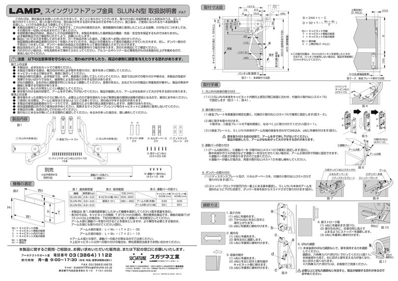
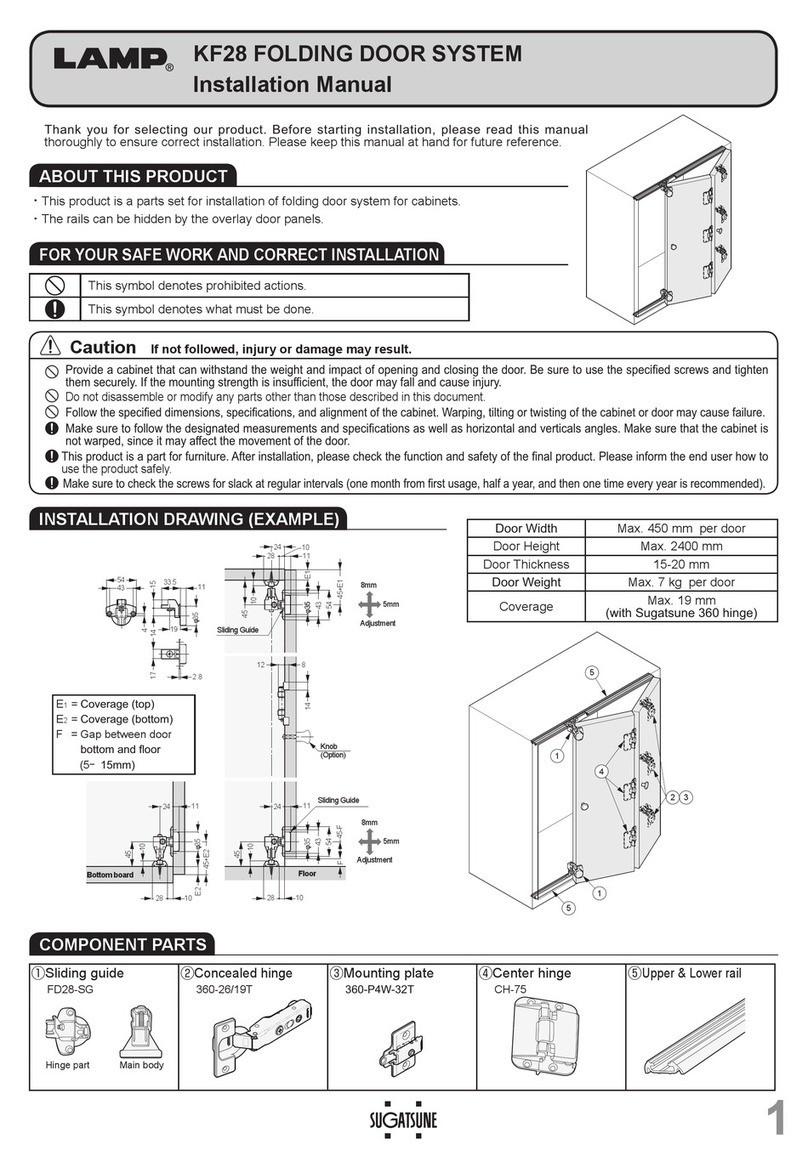
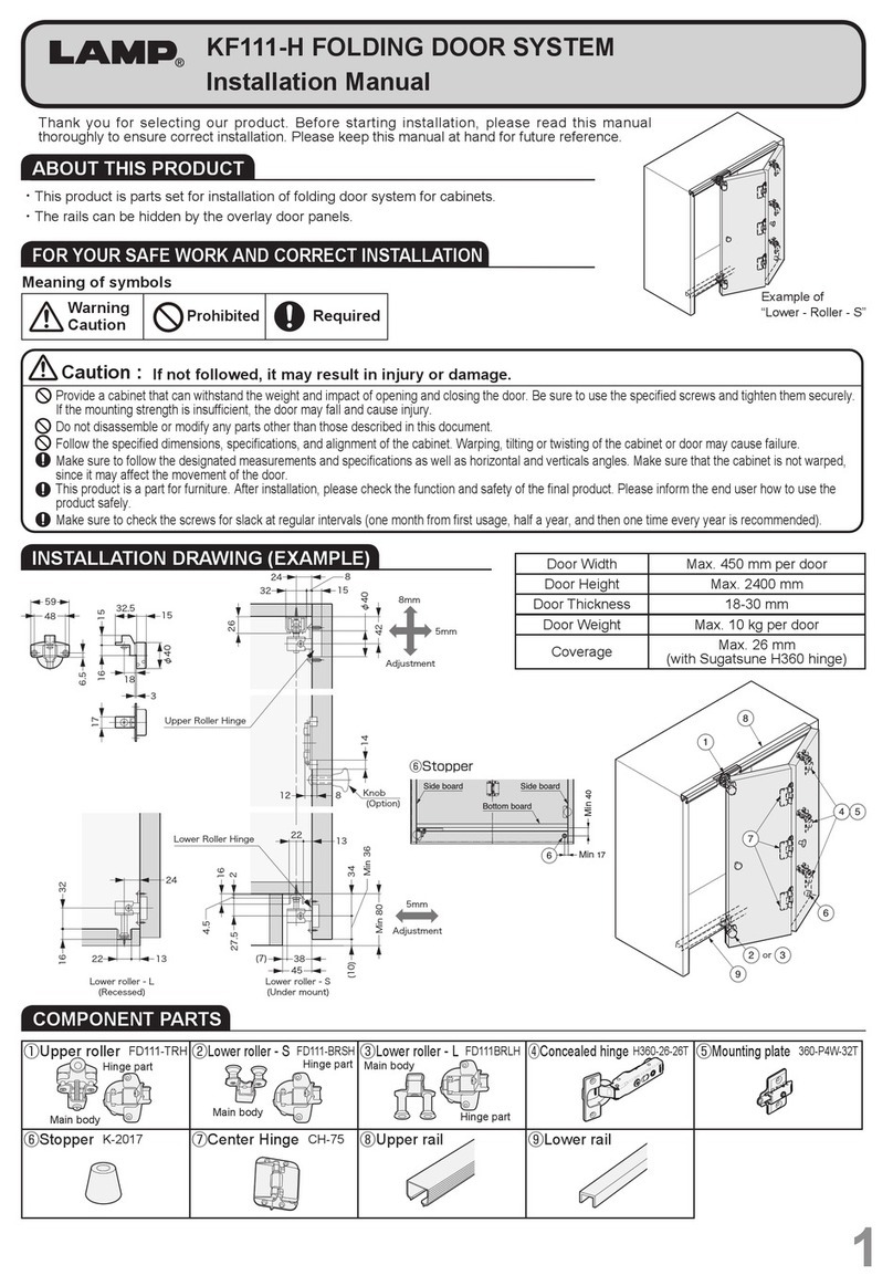
  9. Lamp HC-70 User manual

Lamp HC-70 User manual

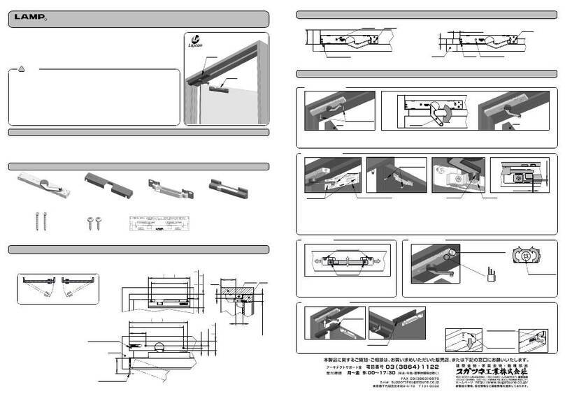
内容物に間違いがないことを確認してください。本品は左右勝手兼用です。
注意
・加工寸法は必ずお守りください。誤った加工寸法で無理な取り付けを行うと、
 本来の性能を発揮できない恐れがあります。
このたびは、弊社製品をお買い上げいただき、誠にありがとうございます。
取り付け作業に当っては本書を良くお読みのうえ、正しく取り付けていただく
ようお願いいたします。
取り付け後は、必ずお使いになる方が本書を保管してください。
■部品構成
青
・つまみを矢印の方向にスライドさせてください。施錠状態でスムーズにカマが出れば正常です。
下図を参考に、本体と受座の中心線が一致するよう切欠加工を行ってください。
(HCー70は本体取付穴φ35貫通穴加工は不要です。)
・HC-70H(表示器付)は、表示器の窓の色が赤→青に変わることを確認してください。
 表示器の窓の赤が施錠状態、青は解錠状態を示します。
 表示が逆転している場合は、取り付け手順の②に戻って取り付け直してください。
13
23.211.8 9
枠
引戸
枠
23.2
11.8
85
57
引戸
 本体取付用ねじ
  (4×25)
取付用木ねじ
(3.8×20)
本体 受座
φ35貫通穴
HC-70 HC-70H(表示器付)
本体 表示器
受座
取付用木ねじ
(3.5×20)
20
2
枠
枠
取付用木ねじ
(3.8×20)
戸厚26〜40mm 取付用木ねじ
(3.5×20)
50
 本体取付用ねじ
  (4×25)
①本体の取り付け
■動きの確認
④受座の取り付け
受座を枠に取付用木ねじ(3.5×20)で取り付けます。
本体を引戸に取付用木ねじ(3.8×20)で取り付ます。
(本体端面と引戸端面とがそろうようにします。)
■取り付け手順
※カマが出ている場合は、つまみをスライド
させカマを収納してください。
つまみ
③表示器の取り付け(HC-70Hのみ)
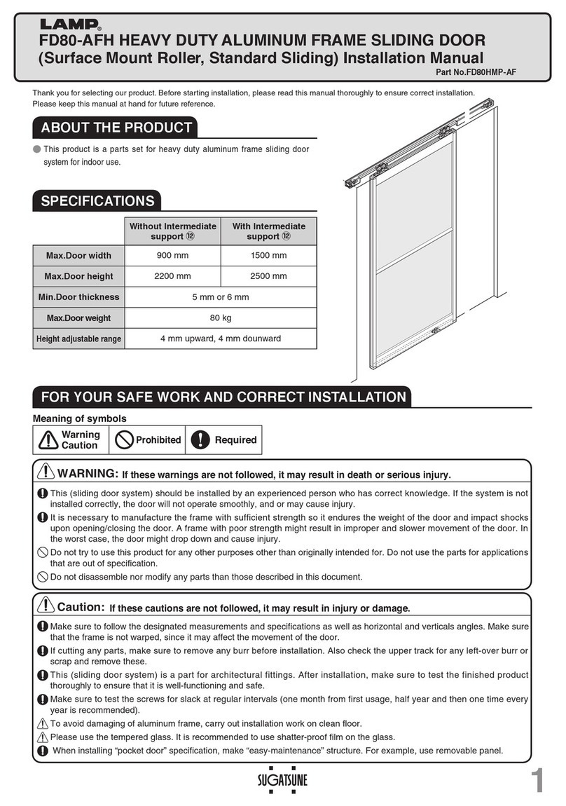
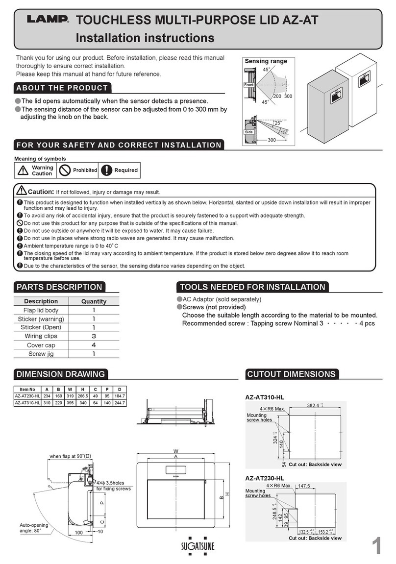
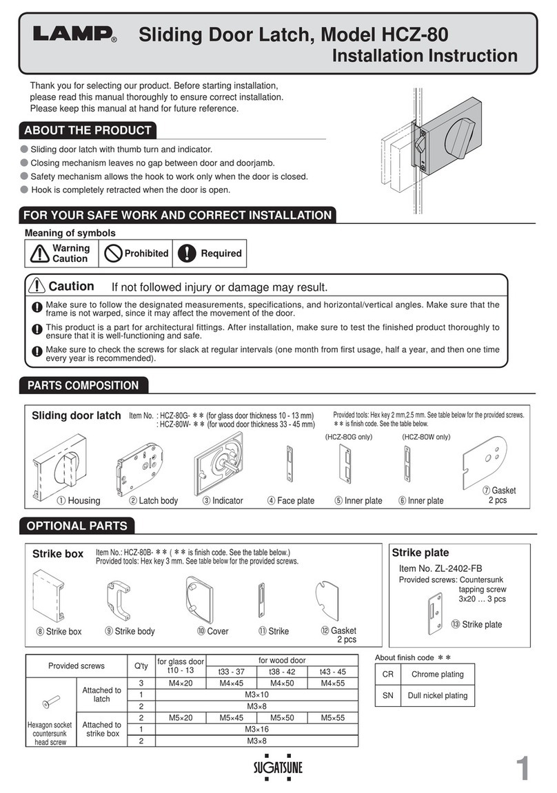
引戸面付カマ錠HC-70
PAT.
引戸面付カマ錠(表示器付)HC-70H
PAT.
■切欠加工図
■部品構成
②カマの収納
軸穴
ピン
表示器のピンを本体の
中央の軸穴に差し込み、
表示器を本体組立ねじ
(4×25)で取り付け
てください。(この時、
表示器の窓の色は青に
してください。)
R取付説明書
20
85
赤
表示器
本体
受座
本体
引戸
2
受座を枠の端面に取り付ける場合
受座を枠の中央に取り付ける場合
取付用木ねじ
(3.8×20)
引戸
引戸
枠の中央への取り付け 枠の端面への取り付け
取付用木ねじ(3.5×20)
カマ
青
つまみ
カマ
表示器
表示器
端
面
端
面
(HC-70Hのみ)
HC-70H施錠状態 HC-70H解錠状態
図はHC-70Hを示します。
2013.04 PRINTEDINJAPAN 0108-2 
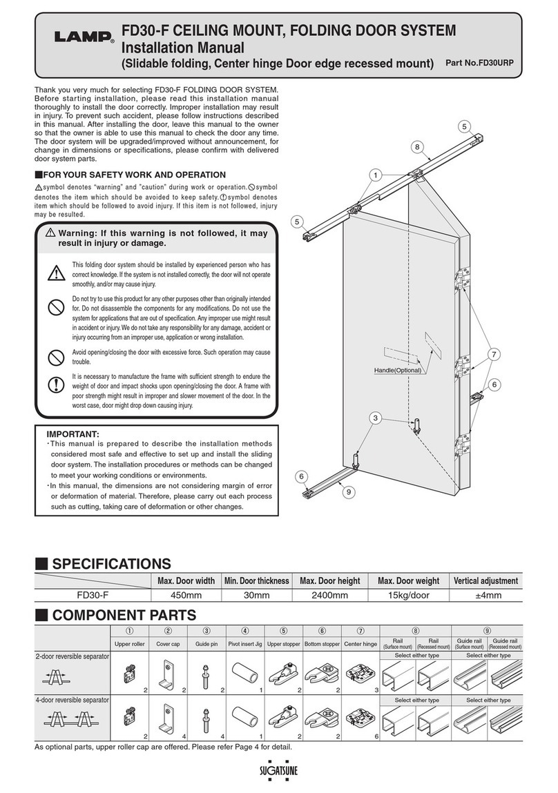
Please check to be sure the package contains all required parts. This product can be used for either the right
or left side.
CAUTION
Please adhere strictly to the dimensions provided for installation. If incorrect
dimensions are used, the product may not perform as originally designed.
Please read this manual carefully for correct installation of this product. After installation
is complete, please be sure to pass this manual to the user who should keep it for later
consultation.
■部品構成
Blue
Slide the knob in the direction of the arrow. Operation is normal if the hook comes out smoothly while door
is locked.
With the HC-70H (with indicator), check to be sure color of indicator window changes from red to blue.
Door is locked when the indicator is red, and unlocked when it is blue . If these colors are reversed, please
redo stop (2) above.
Refer to the diagrams below to perform notch work so that the centerlines of the latch body and strike plate
are aligned. (The
φ
35 through hole is not required for the HC-70.)
13
23.211.8 9
23.2
11.8
85
57
Latch body mounting
screws
(
4 x 25
)
Wooden screws
(
3.8 x 20
)
Latch body Strike plate
φ
35 through hole
HC-70 HC-70H(withindicator)
Latch body Indicator
Strike plate
Sliding door
20
2
Frame
Frame
Wooden screws
Doorthickness26-40mm
Wooden screws
(
3.5 x 20
)
50
 
Latch body mounting screws
 
 (
4 x 25
)
Wooden
screws
(1) Mounting the Latch Body
CheckingOperation
(4) Mounting the Strike Plate
Use the wooden screws (3.5 x 20) to mount the
strike plate to the frame.
Use the wooden screws (3.8 x 20) to mount the latch body to
the sliding door.(Be sure the edge of the latch body is aligned
to the edge of the door.)
Installation Procedure
If the hook is protruding out of the latch body,
slide the knob to retract it inside.
Knob
(3) Mounting the indicator (HC-70H only)
Sliding Door Latch, Model HC-70 PAT.
Model HC-70H (with Indicator) PAT.
Diagrams Notch for Work
Required Parts
(2) Retracting the Hook
Spindle hole
Pin
Insert the pin of the indicator
into the spindle hole at the
center of the latch body,and
use the latch body mounting
screws (4 x 25) to mount
the indicator to the latch
body. (At this time,set the
color of the indicator
window to blue .)
RInstallation Manual
20
85
Red
Indicator
Latch body
Strike
plate
Latch body
Sliding door
2
Ifthestrikeplateistobemounted
atthecenteroftheframe:
Wooden screws
(
3.8 x 20
)
Sliding door
Sliding
door
Mounting strike plate
to the center of the frame
Wooden screws (3.5 x 20)
Hook
Blue
Knob
Hook
Indicator
Indicator
Edge
Edge
(
HC-70H only
)
HC-70H in Locked Position HC-70H in Unlocked Position
The HC-70H is shown in this diagram.
Ifthestrikeplateistobemounted
attheedgeoftheframe:
Mounting strike plate
to the edge of the frame
(
3.5 x 20
)(
3.8 x 20
)
Frame Frame
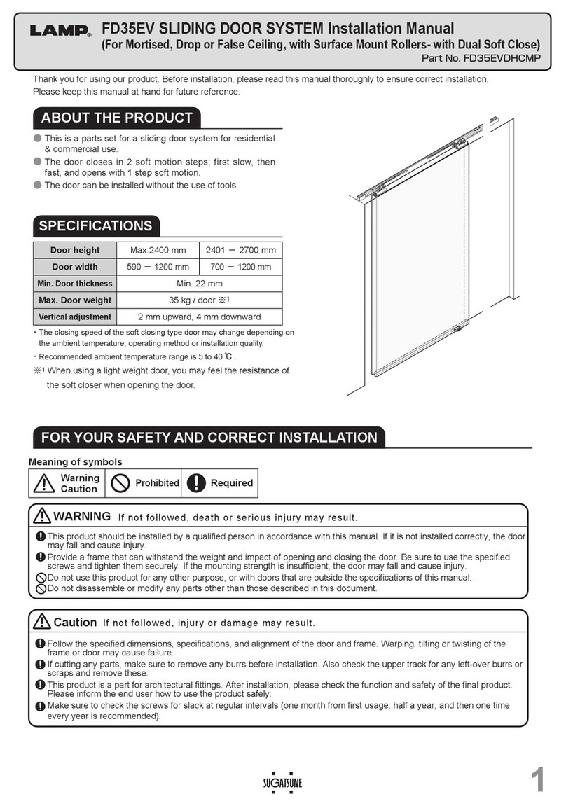
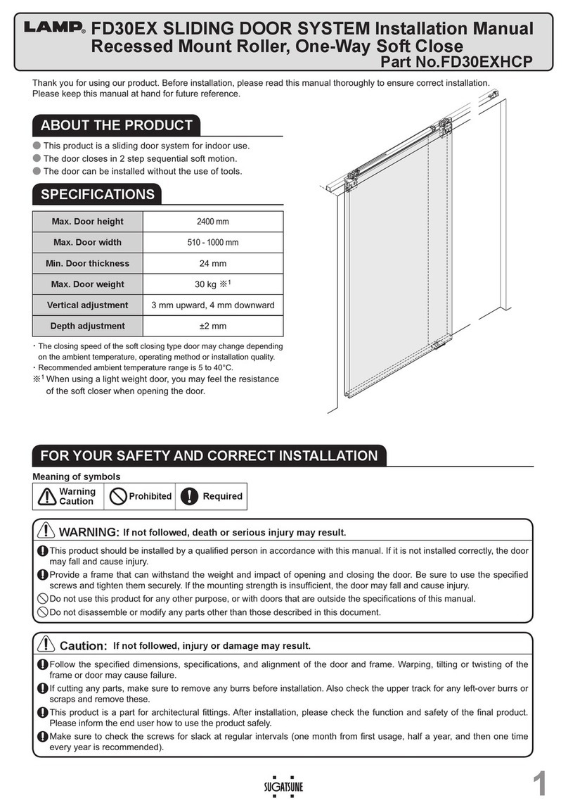
This manual suits for next models

1

Other Lamp Door Opening System manuals

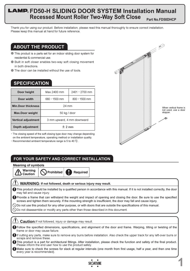
Lamp FD50-H User manual

Lamp

Lamp FD50-H User manual

Lamp XL-GC07D-CR User manual

Lamp

Lamp XL-GC07D-CR User manual

Lamp FD50-H User manual

Lamp

Lamp FD50-H User manual

Lamp FD50-H User manual

Lamp

Lamp FD50-H User manual

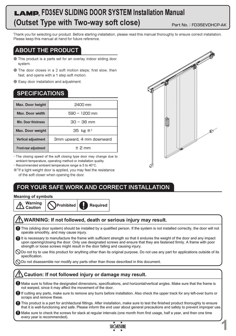
Lamp FD35EV User manual

Lamp

Lamp FD35EV User manual

Lamp FD30-F User manual

Lamp

Lamp FD30-F User manual

Lamp FD80-H User manual

Lamp

Lamp FD80-H User manual

Lamp FD50-H User manual

Lamp

Lamp FD50-H User manual

Lamp FD30-F User manual

Lamp

Lamp FD30-F User manual

Lamp HCZ-80 User manual

Lamp

Lamp HCZ-80 User manual

Lamp KF28 User manual

Lamp

Lamp KF28 User manual

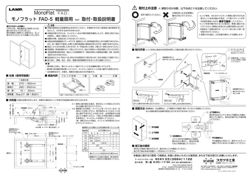
Lamp MonoFlat FAD-5 User manual

Lamp

Lamp MonoFlat FAD-5 User manual

Lamp AZ-AT230-HL Instruction Manual

Lamp

Lamp AZ-AT230-HL Instruction Manual

Lamp FM150PRO User manual

Lamp

Lamp FM150PRO User manual

Lamp FD35EV User manual

Lamp

Lamp FD35EV User manual

Lamp LDD-S User manual

Lamp

Lamp LDD-S User manual

Lamp HC-30L User manual

Lamp

Lamp HC-30L User manual

Lamp FD35EV User manual

Lamp

Lamp FD35EV User manual

Lamp FD35EV User manual

Lamp

Lamp FD35EV User manual

Lamp HDSN-30K User manual

Lamp

Lamp HDSN-30K User manual

Lamp KF111-H User manual

Lamp

Lamp KF111-H User manual

Lamp SLUN-N User manual

Lamp

Lamp SLUN-N User manual

Lamp FD30EX User manual

Lamp

Lamp FD30EX User manual

Lamp FD50-H User manual

Lamp

Lamp FD50-H User manual

Popular Door Opening System manuals by other brands

CES EB1100 Assembly and operating manual

CES

CES EB1100 Assembly and operating manual

Assa Abloy MAB 609 + AC572 Mounting instructions

Assa Abloy

Assa Abloy MAB 609 + AC572 Mounting instructions

Assa Abloy Corbin Russwin ED4000 Series installation instructions

Assa Abloy

Assa Abloy Corbin Russwin ED4000 Series installation instructions

Chamberlain T installation instructions

Chamberlain

Chamberlain T installation instructions

Chamberlain MyQ Garage user guide

Chamberlain

Chamberlain MyQ Garage user guide

Assa Abloy Norton PR7500 installation instructions

Assa Abloy

Assa Abloy Norton PR7500 installation instructions

CornellCookson SDCL-5045 Installation instructions and operation manual

CornellCookson

CornellCookson SDCL-5045 Installation instructions and operation manual

Bohle BO 5215496 instruction manual

Bohle

Bohle BO 5215496 instruction manual

Lapcon LAMP NSDX-35 2SL instruction sheet

Lapcon

Lapcon LAMP NSDX-35 2SL instruction sheet

Falcon RM70 installation instructions

Falcon

Falcon RM70 installation instructions

FAAC XKPR125D manual

FAAC

FAAC XKPR125D manual

Record R62 user manual

Record

Record R62 user manual

Eco FSA EFR TS-61 B Assembly instruction

Eco

Eco FSA EFR TS-61 B Assembly instruction

GAL MOVFR installation instructions

GAL

GAL MOVFR installation instructions

CAMDEN CX-ED1959 installation instructions

CAMDEN

CAMDEN CX-ED1959 installation instructions

Eco FSA ECO SR-EFR BG TS-62 G Assembly instruction

Eco

Eco FSA ECO SR-EFR BG TS-62 G Assembly instruction

GEZE Slimdrive SL NT Installation and service instructions

GEZE

GEZE Slimdrive SL NT Installation and service instructions

LCN 4110EDA instruction sheet

LCN

LCN 4110EDA instruction sheet

manuals.online logo
manuals.online logoBrands
  • About & Mission
  • Contact us
  • Privacy Policy
  • Terms and Conditions

Copyright 2025 Manuals.Online. All Rights Reserved.