Lamp ALT-F18LV2 User manual

1
FOLDING POCKET DOOR SYSTEM ALT-F
Installation Manual
Thank you for selecting our product. Before starting installation, please read this manual thoroughly to
ensure correct installation. Please keep this manual at hand for future reference.
WARNING: If these warnings are not followed, it may result in death or serious injury.
CAUTION: If these cautions are not followed, it may result in injury or damage.
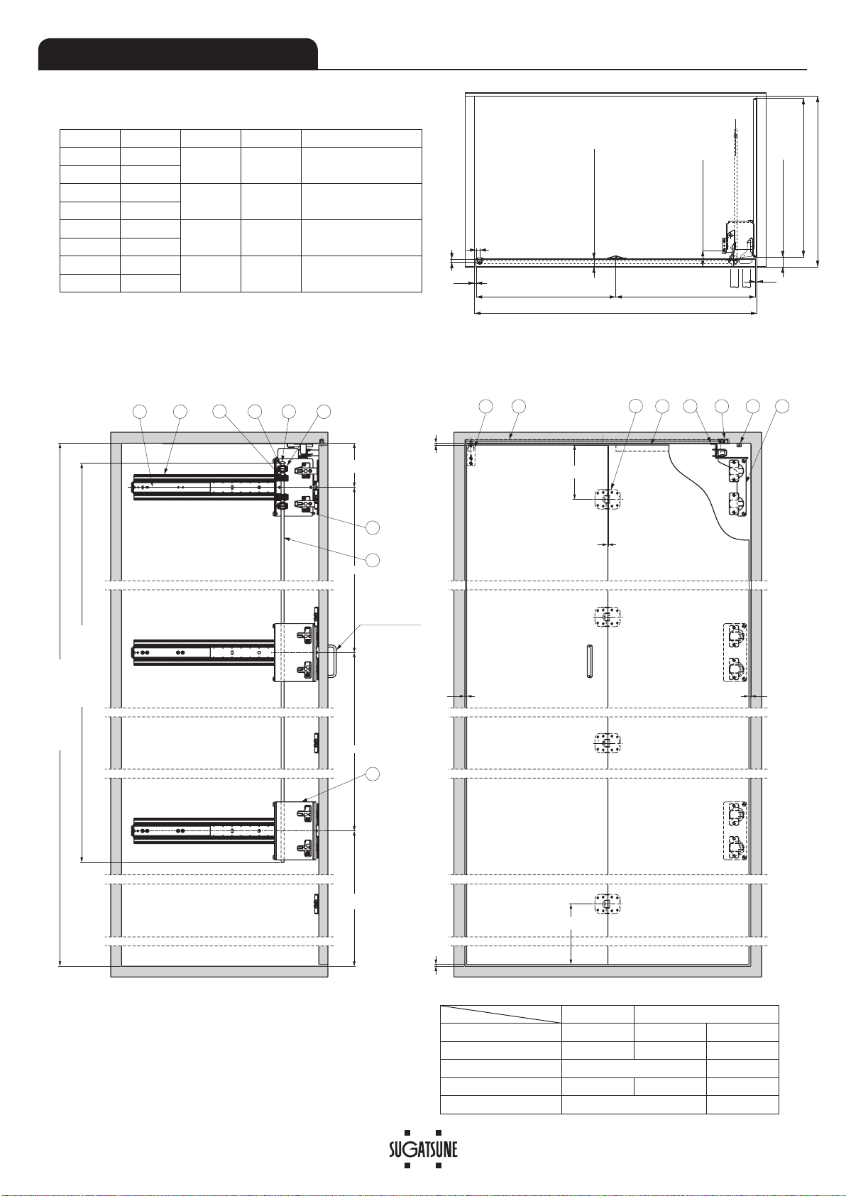
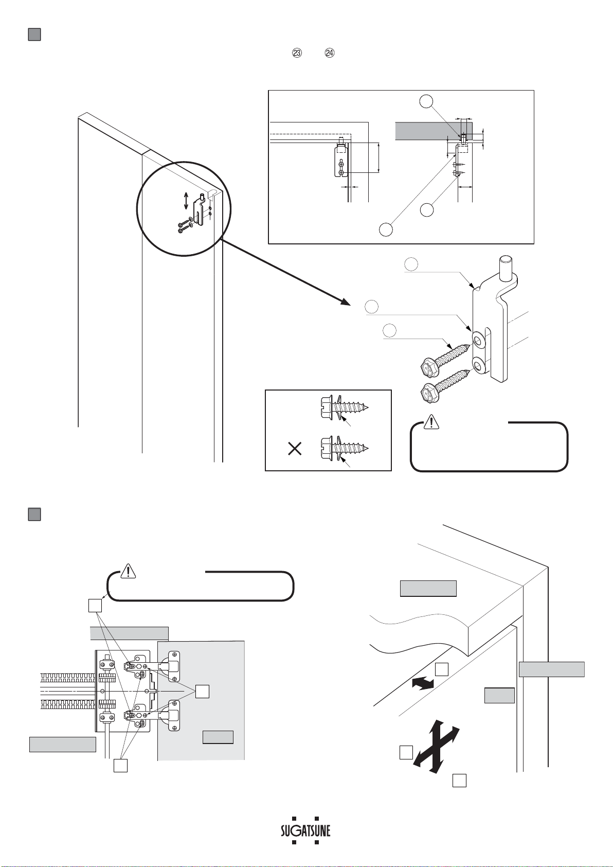
It is necessary to manufacture the frame with sufficient strength so it endures the weight of the door and impact shocks upon
opening/closing the door. Also make sure to only use the designated screws and to fasten them firmly. A frame with poor
strength or loose screws might result in improper and slower movement of the door. In the worst case, the door might drop
down and cause injury.
Do not try to use this product for any other purposes other than originally intended for. Do not use the parts for applications
that are out of specification.
Do not disassemble nor modify any parts than those described in this document.
This (folding door system) should be installed by an experienced person who has correct knowledge. If the system is not
installed correctly, the door will not operate smoothly, and or may cause injury.
This (folding door system) is a part for furniture fittings. After installation, make sure to test the finished product thoroughly to
ensure that it is well-functioning and safe.
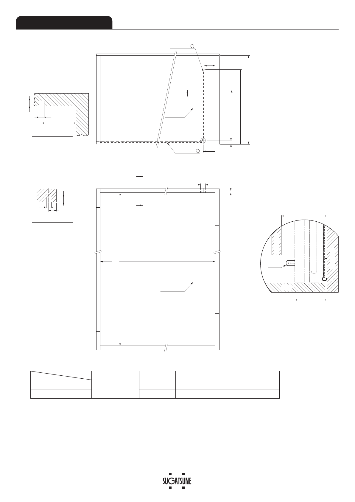
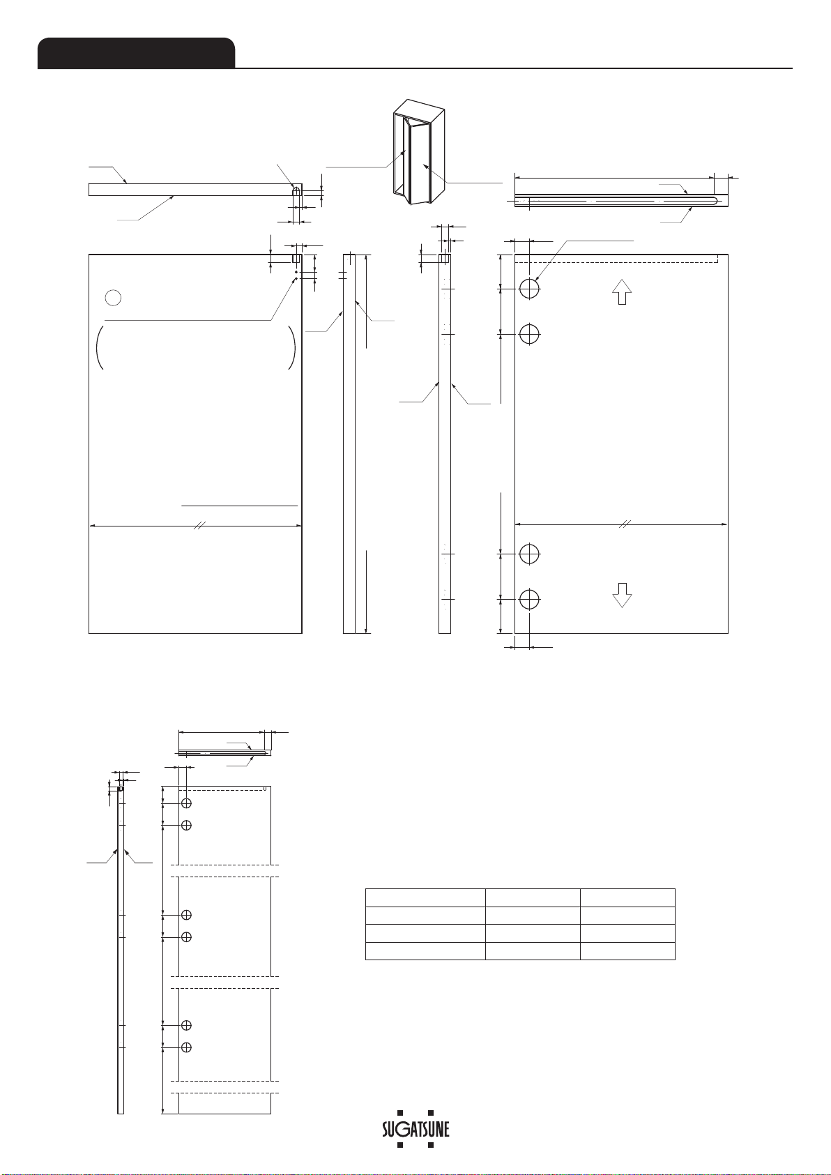
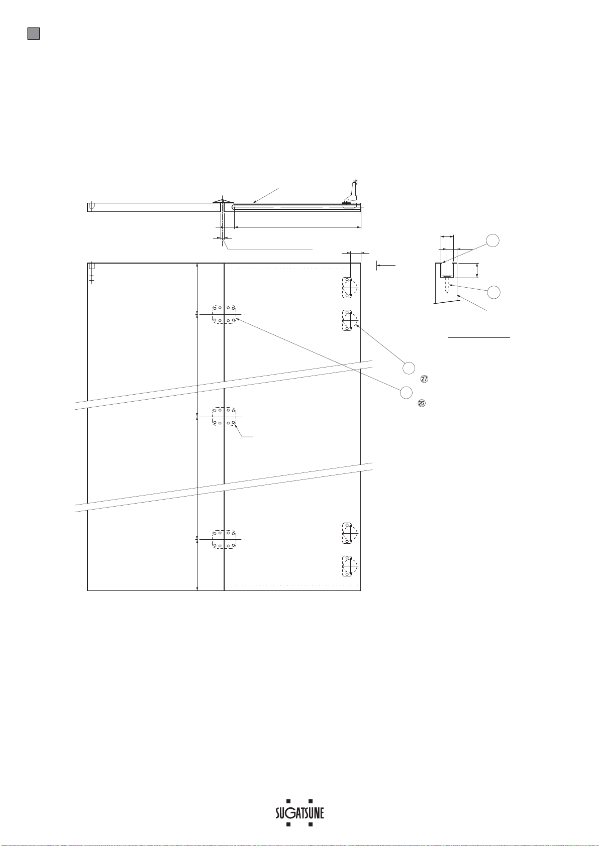
Make sure to follow the designated measurements, specifications, and horizontal/vertical angles. Make sure that the cabinet
is not warped, since it may affect the movement of the door.
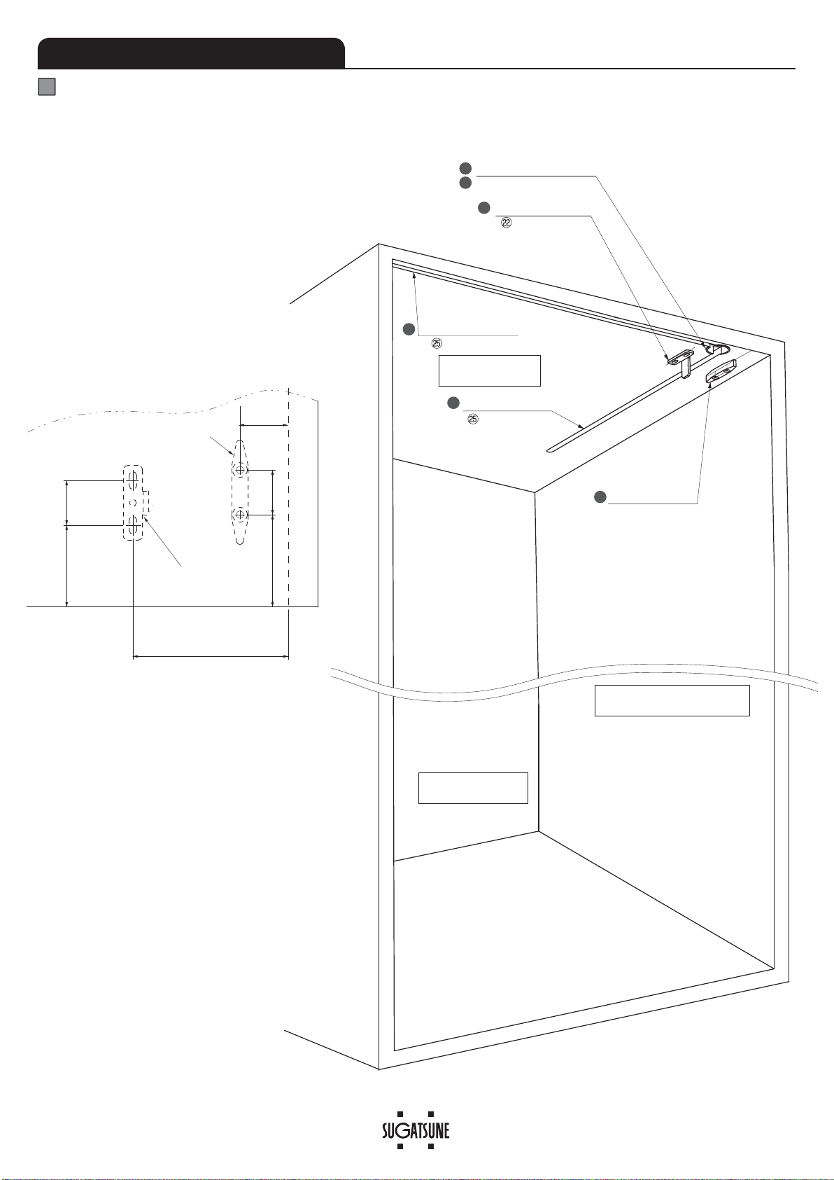
If cutting any parts, make sure to remove any burr before installation. Also check the upper rail for any left-over burr or scrap
and remove these.
Make sure to check the screws for slack at regular intervals (one month from first usage, half year and then one time every
year is recommended).
Prohibited
Warning
Caution Required
Meaning of symbols
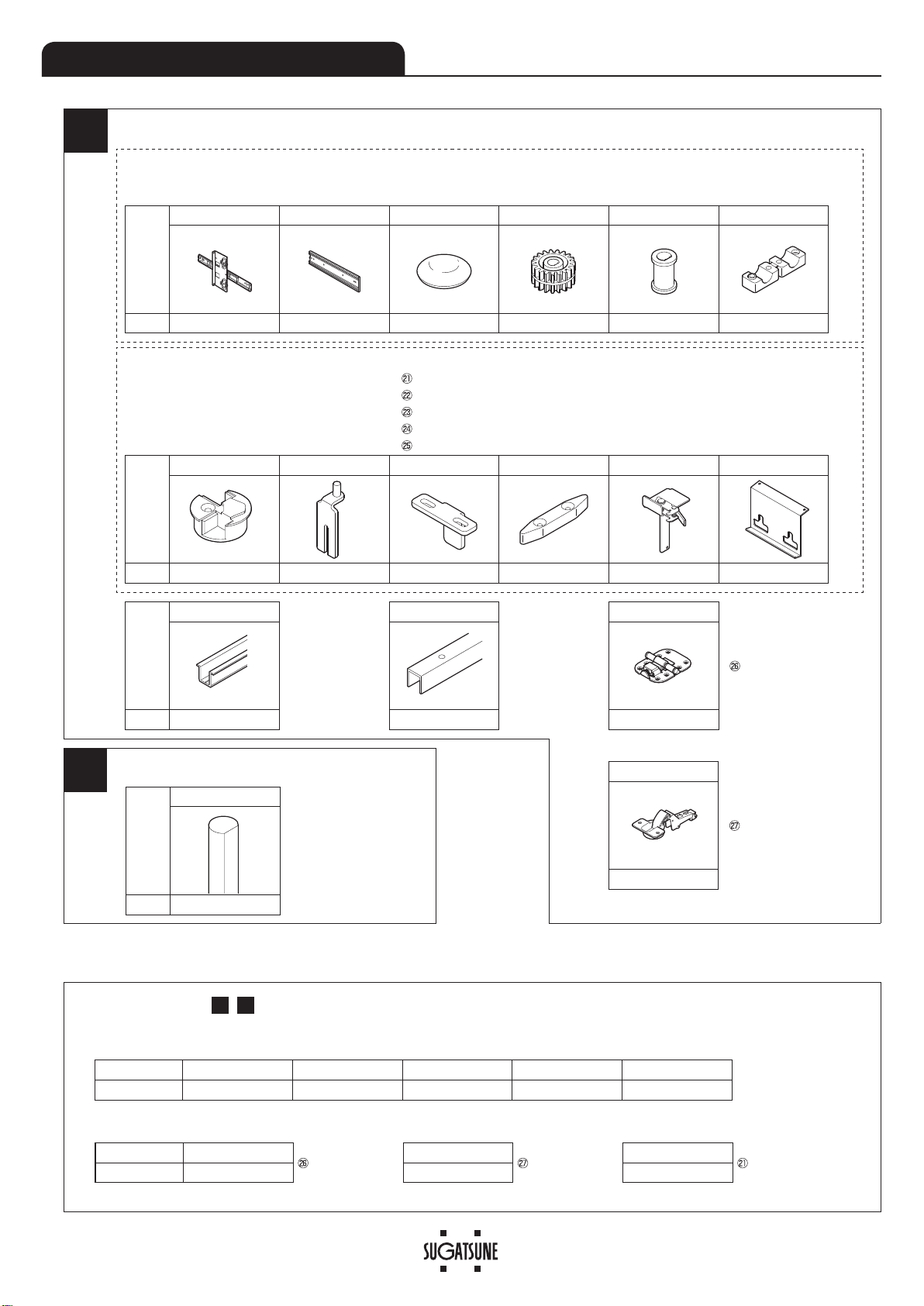
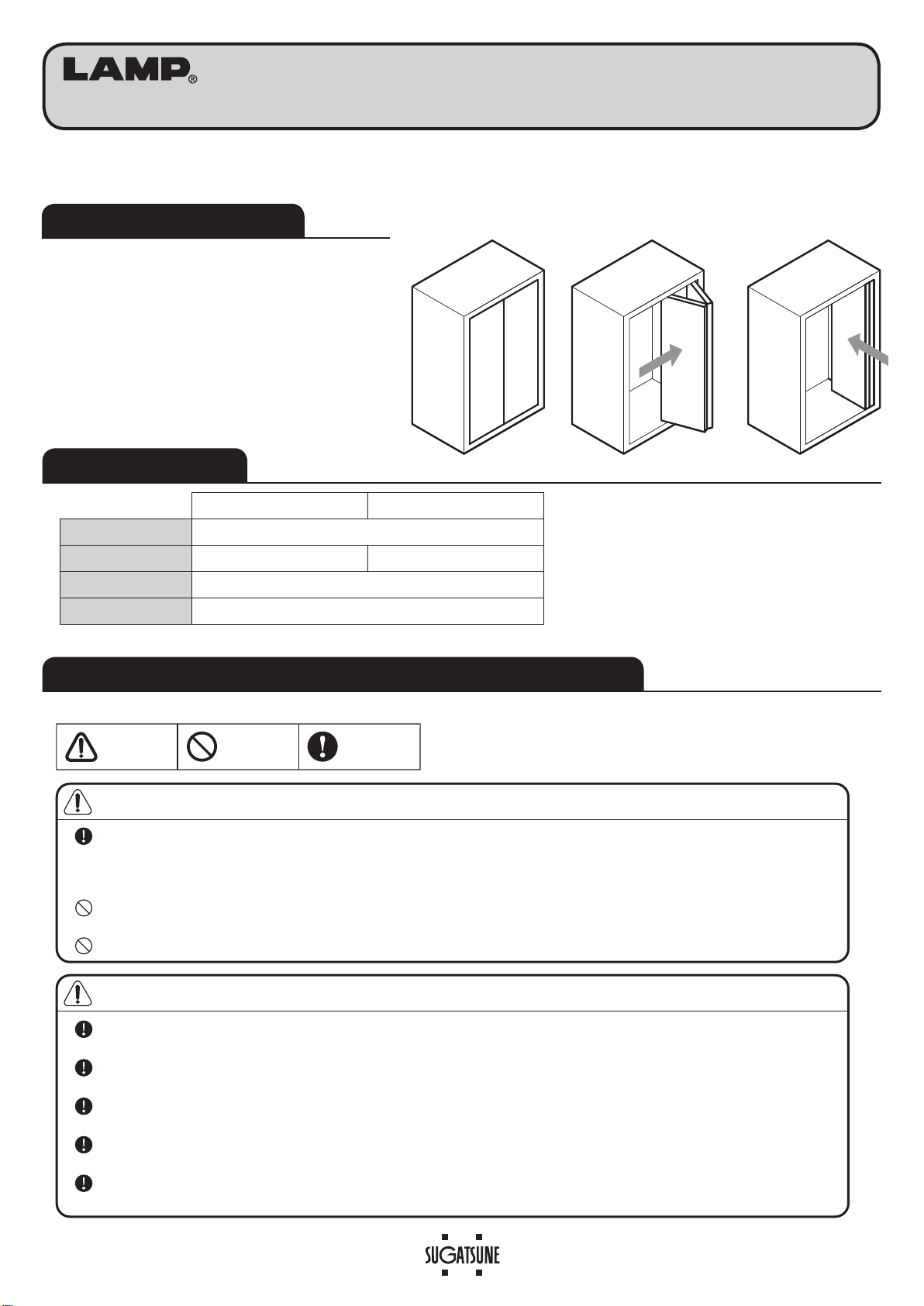
●Pocket door hardware for folding
door system.
●The folding door can be stored inside
the shallow cabinet.
ABOUT THE PRODUCT
2 Rails Type 3 Rails Type
Max. door width 450 mm / door
Max. door height 1830 mm 1831 - 2400 mm
Door thickness 23 - 30 mm
Max. door weight 10 kg / door
SPECIFICATIONS
FOR YOUR SAFE WORK AND CORRECT INSTALLATION

B
A
Pats Name
⑰Connecting bar
Length: 902±13 mm
1207±13 mm
1816±13 mm
Q'ty
1
2
Pats Name
⑬Upper Rail
Pitch end:
Approx. 30 mm
Hole pitch:
Approx. 300 mm
Do not use the
screws attached.
⑭Guide Rail
Pitch end:
Approx. 30 mm
Hole pitch:
Approx. 300 mm
⑮Center hinge
Screws supplied
Countersunk head tapping screw
3.5x16: 24 pcs
・・・
for ⑮
1820mm 1500mm
Q'ty 1 1 3
Connecting bar (1 pc)
PARTS SET (Single folding door)
【1】2 Rails Type: Max. door height: 1830 mm (Max. cabinet inside height: 1840 mm)
Parts set Item Name: ALT-F18LV2, ALT-F18RV2,ALT-F20LV2,ALT-F20RV2
2 Rails Type Screws supplied ⑱Pan head screw (self-tapping) 4x20: 8 pcs (⑥)
⑲Truss head tapping screw 4x20: 18 pcs (①)
Screws Supplied
⑱Pan head screw (self-tapping) 4x20: 8 pcs (⑥)
⑲Truss head tapping screw 4x20: 9 pcs
・・・ for ①
Pocket Door Parts Set Screws supplied ⑳Countersunk head tapping screw 4x20: 8 pcs ・・・・・・・・・ for ⑦⑩⑭
Pan head screw M6x8: 4 pcs ・・・・・・・・・・・・・・・・ for ⑪⑫
Bind head tapping screw 4.5x20: 2 pcs ・・・・・・・・・・・・ for ⑨
+H[DJRQÀDQJHKHDGWDSSLQJVFUHZ[SFV ・・・・・・・ for ⑧
Spring washer 4 mm: 2 pcs ・・・・・・・・・・・・・・・・・ for ⑧
Countersunk head tapping screw 3.5x16 (φ6 head): 10 pcs ・・
for ⑬
【2】3 Rails Type:Door height: 1831 - 2400 mm (Cabinet inside height: 1841 -2440 mm)
Item Name: ALT-F18LV3, ALT-F18RV3,ALT-F20LV3,ALT-F20RV3
Pats Name
①Rail ②Rack ③Cap ④Gear ⑤Bush ⑥Stationary Block
Q'ty221444
Pats Name
⑦Upper Rail Joint
⑧End Guide
⑨Door holder
⑩Angle Stopper ⑪Interlock ⑫
Hinge Cover Bracket
1820mm
Q'ty111111
⑯
Hinge Set
Screws supplied
Countersunk head tapping screw
3.5x20: 8 pcs
・・
for ⑯
4
Name ①Rail ②Rack ④Gear ⑤Bush ⑥Stationary Block
Q'ty11222
Name ⑮Center Hinge Screws supplied
Countersunk head tapping screw
3.5x16: 8 pcs
・・・
for
⑮
⑯Hinge set
Screws supplied
Countersunktappingscrew
3.5x20: 8 pcs
・・・
for
⑯
⑫Hinge Cover Bracket
Screws supplied
Pan head screw
M6x8: 2 pcs
・・・
for
⑫
Q'ty 1 2 pcs 1
This includes above , and below parts.
A B

3
12
10
A (Rail length)
Max. 450
Max. 450
Door thickness: 23 - 30
(5)
(5)
(Max. 910)
Door thickness + 6.3
Door thickness + 28
B
15
81110714 913
12 3
456
12
16
17
(not included)
Handle
※1
※1
※2
150
150
Min. 0.5
(5)
(5) (5)
(5)
122
(P2)P1P1
Connecting bar length
Cabinet inside height: H
The procedure describes the right handed opening type.
The left-handed opening is installed in the opposite position.
INSTALLATION DRAWINGS
Installation Drawing (3 Rails Type)
※1 Position of rails
The dimension of the design is 125, but take into
consideration that the door may sag when installing the
door.
※2 Position of handle
See page 4 when placing a middle board.
2 Rails Type 3 Rails Type
Door Height Max. 1830 1831 - 1903 1904 - 2400
Cabinet Inside Height: H Max. 1840 1841 - 1913 1914 - 2410
Connecting Bar Length H-110 1803
P1 H-250 (H-250)/2 831
(P2) 128 H-1784
Item Name
Opening direction
Rail Length (A)
Door Storing Cabinet Depth (B)
ALT-F18LV2
Left 460.4 355.6
Min. 466.7 + Door thickness
ALT-F18RV2
Right
ALT-F20LV2
Left 511.2 406.4
Min. 517.5 + Door thickness
ALT-F20RV2
Right
ALT-F18LV3
Left 460.4 355.6
Min. 466.7 + Door thickness
ALT-F18RV3
Right
ALT-F20LV3
Left 511.2 406.4
Min. 517.5 + Door thickness
ALT-F20RV3
Right

4
68
10
10
キャビネット間口高さの内寸法=扉高さ+10Cabinet Inside Height = Door height + 10
68
D
Door thickness - 3
φ30
75
12
E
Dimension A-A
Dimension B-B
A
A
B
B
※3
※3
Cabinet Inside Width
=( Door Width ×2)+10
Middle Board
Middle Board
Upper Rail b
Upper Rail a
Door thickness-10
10
10
Min.120
(
90
)
when door thickness is 30 mm
Handle
Door
Middle Board
Side Board
8VHKDUGZRRGIRUFRUHPDWHULDOIRUSDUWV¿WWLQJDUHD
When installing middle board
Position middle board to avoid
interference with handle and angle
stopper.
Please drill a new hole within 50 mm from the end of upper rail after cutting the rail.
Do not deform when the rail is cut.
Deburr the cut surfaces.
※3 : Position (center) of φ30 hole
Length of Upper Rail ⑬
CABINET DIMENSION
Rail ⓐRail ⓑDE
ALF-F18(L/R) Door Width × 2 - 69 375 410 Min. 466.7 + Door thickness
ALF-F20(L/R) 425 460 Min. 517.5 + Door thickness

5
Rear
Rear
Drill 2 holes (for hexagon flange
head tapping screw 4x16)
φ40 depth 13
Guide rail length = Door width - 30
Front
Front
Front Rear
Front
Rear
17
17
15
14 37
33
96(72)
10
5
14
12
72
96
33
30
4
R7
23
Cabinet inside width - 10.5
Door thickness=
(Max. 450)
2
Door height = Cabinet inside height - 10
Top
Bottom
Door height - 336
Use hardwood for core material and
make sure to tighten screws firmly to
prevent to loose the screws.
Moving door
Hanging door
96 72
33
D196D196D2
Rear
Guide rail length
= Door width - 30
Front
Front Rear
17
15
30
4
8VHKDUGZRRGIRUFRUHPDWHULDOIRUSDUWV¿[LQJDUHD
【1】2 Rails Type
【2】3 Rails Type
※4Please drill a new hole within 50 mm from the end of rail after
cutting the rail.
Do not deform when the rail is cut.
Deburr the cut surfaces.
DOOR DIMENSION
●Moving door
●Hanging door ●Moving door is the same as 2 rails type
●Hanging door
Door height 1831 - 1903 1904 - 2400
Cabinet inside height: H 1841 - 1913 1914 - 2410
D1 (
Door height - 432
)
/2
735
(D2) (72) Door height - 1830

Rear board
Right side board
Top board
⑩Inner guide ※6
(⑳screw 4x20)
⑬Upper rail ※5
⑬Upper rail ※5
( screw 3.2x15)
( screw 3.2x15)
⑦Upper rail joint
(Fix with ⑳screw 4x20.)
⑨Angle stopper
⑩Inner guide
104.5
28 +Door thickness
62
(30)
(30)
32.5
Side Board
1
4
6
3
5
2
⑨Angle stopper ※6
( screw 4.5x20.)
6
1Installing Parts on the Top Board
Install parts in order of ❶to ❻.
※5See p. 4 for the length of Upper rail⑬
※6 Position installing ⑨⑩
(Top board viewed from top)
INSTALLATION PROCEDURES

7
Arrow View A
Rear face
20 screw 4x20
Guide rail
14
17
15
11.5
Moving door Hanging door
Hinge set
( screw 3.5x20)
16
Rear face
A
15 Center hinge
( screw 3.5x16)
30
33
Guide rail length = Door width - 30
Space of Min. 0.5 mm
between doors.
〃〃
150150
※7
2Installing Parts
(1) Fix hinge set ⑯into the hanging door.
(2) Fix guide rail ⑭into grooves in the upper blocks in hanging door.
(3) Fix center hinge ⑮.
2 rails type : Fix as show in the below drawing.
3 rails type : Fix 2 center hinges within 150 mm from the end.
※7Another 2 hinges should be mounted in even distance each other.

8
screw M6x8
Rail Interlock
111
21
Front end hole
⑲screw 4x20
Door thickness + 6.3
Roller comes to the front.
Connecting bar
17
Rack Rail
Guide pin 1
2
Cabinet inside height: H
96
(128)
Connecting bar length: H - 110
122
Top Board
Bottom Board
H-250
Cabinet inside height: H
(P2) P1 P1 122
Bottom Board
Top Board
Connecting bar length: 1803
96
3Assembling Interlock to Rail
Assemble interlock⑪to rail①with screw .
4Installing Rails and Racks
❶Positions for rails
<As assembled>
【1】2 Rails Type 【2】3 Rails Model
Dimensions for 3 rails model
❸Fixing Rails
Fix rails in order to be parallel each other.
❷Fit rail to the rack.
❹Cutting of connecting bar
Cut connecting bar ⑰as in above drawings.
Door height 1831 - 1903 1904 - 2400
Cabinet inside height: H 1841 - 1913 1914 - 2410
P1 (H-250)/2 831
(P2) 128 H-1784
CAUTION
Deburr the cut surfaces of
the shaft completely.

Bottom Board
Side Board
Stationary Block
Rail
Bush
Rack
Rail bracket
Stationary Block
Gear
Connecting bar
Rack
screw 4x20 (self-tapping)
Hei
g
ht ad
j
ustment
Hinge set
Door
5
6
2
4
17
16
18
1
6
2
9
5Assembling Connecting Bar and Gear
Assemble gear, connecting bar, bush, and cap as
shown in the drawing.
6Assembling Gear into Rail
(1) Pull the rail bracket until the end of the rail.
(2) Engage the rack and gear of connecting shaft. Fix the stationary block as in below drawing.
7Hanging Doors
The work of hanging the doors must always be
carried out by a team of two workers.
Install the door to mount the hinge set onto mounting
plates.
See 9for door adjustment instructions.
Cap
Bush
Connecting bar
“THIS SIDE UP”
Gear
17
3
5
4
<Shaft mounted on the rail>
CAUTION
Make sure to check the direction of gear.
Be sure to push the cap into pinion shaft strongly.
CAUTION
0DNHVXUHWRWLJKWHQDGMXVWPHQWVFUHZV¿UPO\
WR¿[

Height
adjustment
51
(5)
Door thickness
23 - 30
10(5)
17
10
Top Board
Door
Top Board
Side Board
Upper rail
13
23 Screw 4x16
8End guide
End guide
Screw 4x16
8
23
Spring washer 4 mm
24
10
OK
Top Board
Side Board Door
3
2
1
Side Board
Backward
Forward
Up
Right
Left
Down
1
3
2
Top Board
Door
8Installing End Guide
Insert the end guide ⑧into upper rail ⑬DQG¿[ZLWK and after height adjustment.
9Adjusting Doors
CAUTION
Do not over loosen these screws.
CAUTION
Make sure to tighten screws
firmly to prevent to loose
while operating.

11
Hinge cover bracket
Rail
Screw M6x8 12
1
21
10
Assembling Hinge Cover Bracket
Assemble hinge cover bracket ⑫to rail ①.
(As for 3 slides model, assemble it to middle rail, too.)
<Hinge cover bracket as assembled>

12
SUGATSUNE KOGYO CO.,LTD
Tokyo, JAPAN
SUGATSUNE KOGYO (UK) LTD
Reading, UK
Phone: +44 118 9272 955
E-mail:[email protected]
SUGATSUNE EUROPE GmbH
Dusseldorf, GERMANY
Phone: +49 211 53812900
E-mail:[email protected]
SUGATSUNE SHANGHAI Co., LTD
Shanghai, CHINA
Guangzhou, CHINA
SUGATSUNE KOGYO INDIA PRIVATE LIMITED
Mumbai, INDIA
SUGATSUNE AMERICA, INC
California, USA
Chicago, USA
Phone: +1 312 461 1081
E-mail:[email protected].
SUGATSUNE CANADA, INC.
Phone: +1 514 312 5267
E-mail:[email protected]
2018.06 0754-9
This manual suits for next models
7
Table of contents
Other Lamp Indoor Furnishing manuals