Lamp ALT-ST15-D10 User manual

1
Thank you for selecting our product. Before starting installation, please read this manual thoroughly to ensure correct installation.
Please keep this manual at hand for future reference.
Installation Manual
ALT-ST15-D10
POCKET DOOR SYSTEM <OVERLAY> SOFT CLOSING
ABOUT THE PRODUCT
●This product is hardware for vertical pocket doors in furniture,
enabling slow door closing.
●The door is stored inside the cabinet.
●The door incline can be easily adjusted via a 5-stage angle retention
mechanism.
SPECIFICATION
Caution Prohibited Required
Caution If not followed, injury or damage may result.
• Provide a cabinet that can withstand the weight and impact of opening and closing the door. Be sure to use the specified screws
and tighten them securely. If the mounting strength is insufficient, the door may fall and cause injury.
• Follow the specified dimensions, specifications, and alignment of the cabinet. Make sure that the cabinet is not warped, since it
may affect the movement of the door.
• Position the handle so that the hand holding the handle does not strike the side board.
• When moving the cabinet, remove the door and re-assemble it at the site.
• This product is a part for furniture. After installation, check the function and safety of the final product.
• Make sure to check the screws for slack at regular intervals. (one month and six months from first usage and then once every
year is recommended).
• Be sure to inform users of the precautions below regarding opening and closing.
• Do not force the door to open past 90°. Damage may result.
• When closing the door, pull it out until the catch clicks and then close it.
• Repeated opening and closing may cause the inner rail to come off, shortening the door movement distance.
Push the door fully inward or pull it fully out to correct the deviation.
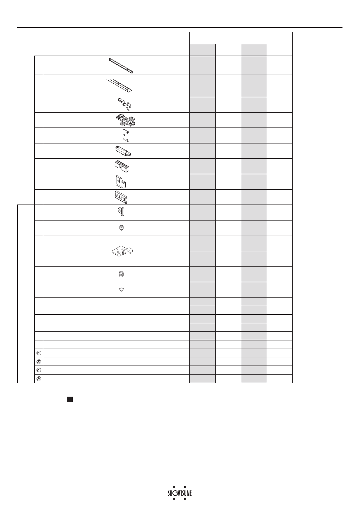
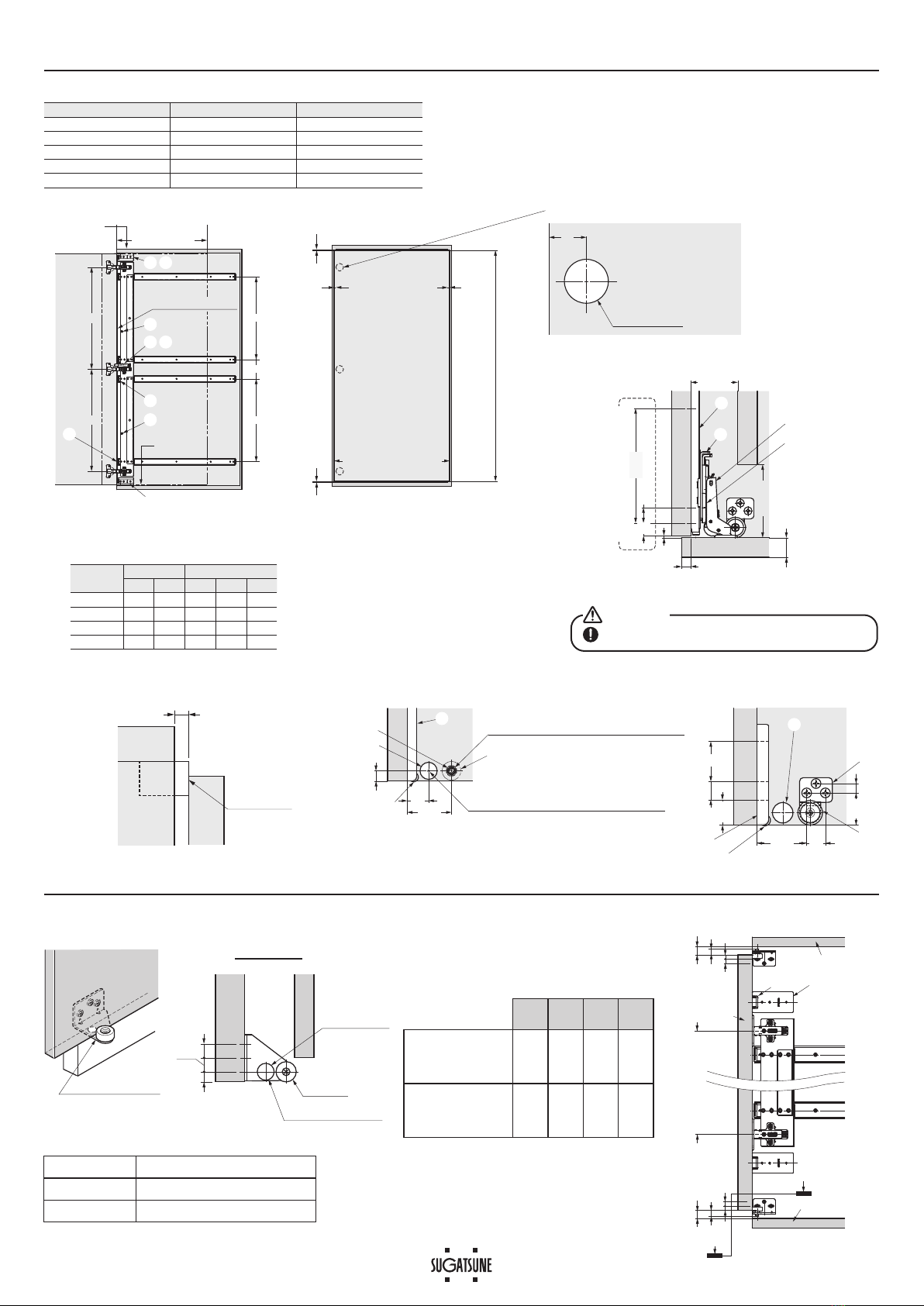
Type S M L LL
Rail Q’ty 2244
Door Width Max. 600 mm
Door Height 500 - 700 mm 700 - 900 mm 900 - 1200 mm 1200 - 1600 mm
Door Thickness 18 - 20 mm
Door Weight Max. 9 kg Max. 9 kg Max. 15 kg Max. 15 kg
Type
Size of rail
FOR YOUR SAFETY AND CORRECT INSTALLATION
ALT - ST15 - D10S - 16
Item Name Guide

2
Overlay (ST15-D10)
S Type M Type L Type LL Type
①
Rail※1
AL80C
16 - 28 inches 2244
②
Connecting plate ALT-ST15-S
ALT-ST15-M
ALT-ST15-L
ALT-ST15-LL
1111
③Concealed hinge SCAF-7G99 2233
④Hinge mounting plate SBAR3R 2233
⑤Mounting plate ALT-MP32 2233
⑥Damper unit SD0S8SNG 1111
⑦Damper base SDARX99 1111
⑧Door stopper ALT-ADS 2233
⑨Protector ALT-ADP 2222
Parts Set
⑩Catch※2
AL127-CH 2233
⑪Roller DU19-B4SBR 2222
⑫
Roller bracket ALT-2V-AB 1111
ALT-2V-BB 1111
⑬Insert nut SC-107-13 2222
⑭Slider G-175 2222
⑮ALT-A-M5 Adjustment bolt 1122
⑯Bind head tapping screw 3.5×15 20 20 36 36
⑰Bind head tapping screw 4×16 6666
⑱Raised countersunk head tapping screw 3.5×15 4466
⑲+H[DJRQÀDQJHKHDGVFUHZ0î 4488
⑳+H[DJRQÀDQJHKHDGVFUHZ0î 4488
Low countersunk head screw M4×8 2233
Raised countersunk head screw M4×10 4466
Countersunk head screw M4×14 1111
Hex key 1111
※1Do not cut rails. Rail sizes (inches) include 16, 19, 22, 24, and 28.
※2This catch holds the door at the pulled-out position. Be sure to mount it on the uppermost and lower slide rails
(For details, see P.4 3).
COMPONENT PARTS/QUANTITY

3
DIMENSIONS: OVERLAY ※Description is for left-handed product.
Rail Size Door Storing Cabinet Depth
16 315 Min. 420
19 391 Min. 496
22 467 Min. 572
24 518 Min. 623
28 620 Min. 725
■Fixed on the side board
Make middle board removable for maintenance.
Caution
CDE
Door
Door Storing
Door Storage Position
55
Overlay: 10 10
Max. Door Weight
[S Type]...
[M Type]...
[L Type]...
[LL Type]...
Max. 9kg
Max. 9kg
Max. 15kg
Max. 15kg
Max. Door Height
[S Type] 500 - 700
[M Type] 700 - 900
[L Type] 900 - 1200
[LL Type] 1200 - 1600
Door Processing
Side view Front view
34
Backside of door
ϕ40 Depth 13
a
Rail Q'ty
[S Type]...
[M Type]...
[L Type]...
[LL Type]...
2 pcs
2 pcs
4 pcs
4 pcs
b
⑩
⑥
⑮
⑧
⑮
⑦
⑧⑨
⑧⑨
AB
Door width: Max. 600
13
2
15.9
Overlay: 10
Side board
Door Thickness: 18 - 20
3
①
③
④⑤
Arrow a
Min. 48
Min. 75
Middle board
②
117.5
Installation Position for Rail
45.5
22
10.5
Mounting holes (top board/bottom board)
ϕ10 Depth 13
Mounting holes (top board/bottom board)
ϕ3 Depth 10
Side board
⑬
⑪
⑭
Arrow b (for Insert nut)
⑨
⑧
Arrow b (for Roller bracket)
42.5 16
27.5
8
Side board
⑧
⑨
⑫
⑭
⑪
35
20.5
15.9
Side-board bracket
(Optional)
Side board
Door
(Top/bottom)
10.5
14.5
14.5
⑪Roller
⑭Slider
Side-board bracket
(Optional)
Section c-c
Side board
Middle board
Item Name Installation Position
ALT - 2V5BR1 For Lower Right and Upper Left
ALT - 2V5BR2 For Upper Right and Lower Left
Type Hinge pitch Rail pitch
ABCDE
S Type 360 í260 íí
M Type 560 í460 íí
L Type 380 380 260 140 260
LL Type 530 530 430 100 430
Top board
Side board Door
※Install a door stopper
so as to create a 2mm gap.
2
Door stopper
For double doors
c
c
Door
Top board
Bottom board
99 9
12.2
※³Min. 110 ※³Min. 110
⑧⑨
Min. 15 Min. 15
12.2
9
S
Type
M
Type
L
Type
LL
Type
When both upper
and lower side-
board bracket are
used.
580
〜
780
780
〜
980
980
〜
1280
1280
〜
1600
When using a
side-board bracket
on either the top or
bottom.
540
〜
740
740
〜
940
940
〜
1240
1240
〜
1600
The applicable door height varies depending
on the number of brackets used and the
dimensions marked with ※3.

4
1
Mounting the insert nut, roller, and slider
⑭Slider
(3 depth 10)
⑪Roller
⑬Insert nut
(10 depth 13)
<Use insert nut ⑬>
<Use roller bracket ⑫>
⑭Slider
(3 depth 10)
⑪Roller
⑫Roller bracket
⑰Bind head tapping
screw 4×16
Side-board bracket
(Optional)
⑪Roller
⑭Slider
⑰Bind head tapping
screw 4×16
※Mount symmetrically on the top board as well.
■Fixed on the side board
■Fixed on the top and bottom boards
2
Mounting the concealed hinge, hinge mounting plate, mounting plate, and slider
Backside of door
③Concealed hing
e
(I40 Depth 13)
⑱Tapping screw
3.5×15
3
Temporarily fastening the slide rail and mounting the door stopper and protector
Temporarily fasten all rail ends
(outer and inner)
Screws: ⑯Bind head tapping screw 3.5×15
2
Mount catch ⑩
1
Functions when pulled
fully out.
⑩Catch
⑯Bind head tapping screw
3.5×15
⑨Protector
⑧Door stopper
Mount the door stopper and protector
3
⑯
⑨
⑯
⑧
⑧
⑯
⑯
⑨
⑯
⑧
INSTALLATION PROCEDURE ※Description is for left-handed product, LL type.
⑤Mounting plate
④Hinge mounting plate
Overlay
②
Connecting plate
Low countersunk head screw
M4×8
Raised countersunk head screw
M4
×
10
Type S M L LL
Rail
Q’ty 2244
Catch
Q’ty 2233
Catch
mounting
location
[■part]
Mount the damper base and damper unit
LQWKHVSHFL¿HGSRVLWLRQ
⑦Damper base
⑥Damper unit
Countersunk head screw M4×14
※Mount ⑨protector overlapping with the door stopper
at the top and bottom edges of the cabinet.
(If mounted toward the centre, it will interfere with the
connecting plate.)
Type S M L LL
Hinge mounting
plateQ’ty
2233
Damper base
Mounting
location
[■part]

5
4
Temporarily fastening of connecting plate
Temporarily fasten
all rails to connecting plate
Screws: ⑲Hexagon flange head screw M4×6
⑳Hexagon flange head screw M4×8
Temporarily fasten
⑮Adjustment bolts (1 - 2 pcs)
(After tightening, loosen 90° - 180°)
4
5
⑮ALT-AB-M5 Adjustment bolt
Furthest front
⑲
⑳
⑮
Move the connecting plate from
the front to the back, adjusting
all the screw positions so that
it moves smoothly
1Tighten the part (both ends)
Fasten all the parts (near centre)
Screws: ⑯Bind head tapping screw 3.5×15
2
3
1
②
Connecting plate
2
2
3
⑧
Door stopper
⑨Protector
⑨
Protector
5
5DLO¿[LQJ 6
Hanging door
Push the hinge into the hinge
mounting plate
How to remove
1
2

<2> Vertical adjustment screw
<1> Depth adjustment screw
<3> Horizontal adjustment screw
Closing speed adjustment (3 stages)
⑥Damper unit
Slow Fast
7
Adjusting the door
8
Door depth, vertical, horizontal, and closing speed adjustment
⑮Adjustment bolt
②
Connecting plate
Check that the screws fixing the connecting plate and the adjustment bolts are loose.
Lift the door and shift the adjustment bolt backward one level at a time,
to make the door and connecting plate vertical.
5-stage adjustment is possible in accordance with the door weight.
※When there are adjustment bolts at top and bottom, align their positions.
Tighten all the temporarily fastened screws.
1
3
2
12
5
4
3
Front
Back
Before adjustment After adjustment
12
5
4
2
2
2
3
12
5
4
3
⑮
Adjustment bolt
②Connecting plate
Light door
Heavy door
6
Adjustment method
<3>
<3>
<2>
<2>
<1>
<1>
SUGATSUNE KOGYO CO., LTD.
Tokyo, JAPAN
Phone: +81 3 3866 2260
E-mail:[email protected]
SUGATSUNE KOGYO (UK) LIMITED
Reading, UK
Phone: +44 1189272 955
E-mail:[email protected]
SUGATSUNE SHANGHAI CO., LTD.
Shanghai, CHINA
Phone: +86 21 3632 1858
E-mail:[email protected]
Guangzhou, CHINA
Phone: +86 20 6639 3554
E-mail:[email protected]
SUGATSUNE KOGYO INDIA
PRIVATE LIMITED
Mumbai, INDIA
Phone: +91 9867299597
E-mail:[email protected]
Delhi, INDIA
Phone: +91 9867299597
+91 11 45093636
E-mail:[email protected]
SUGATSUNE AMERICA, INC.
California, USA
Phone: +1 310 329 6373
E-mail:[email protected]
Chicago, USA
Phone: +1 630 317 7072
E-mail:[email protected]
SUGATSUNE CANADA, INC.
Montreal, CANADA
Phone: +1 514 312 5267
E-mail:[email protected]
SUGATSUNE KOREA CO., LTD.
Incheon, KOREA
Phone: +82 32 220 0603
E-mail:[email protected]
2023.06 1561-2
SUGATSUNE EUROPE GmbH
Dusseldorf, GERMANY
Phone: +49 211 53812 900
E-mail:[email protected]
Table of contents
Other Lamp Indoor Furnishing manuals
Popular Indoor Furnishing manuals by other brands

Argos
Argos Hygena Genoa 464/2718D Assembly instructions

Muller
Muller MATCH Assembly instruction

Hideaway
Hideaway Concelo Care and maintenance instructions

Ave Six
Ave Six CARRINGTON CAR51A Assembly instructions

ROOMS TO GO
ROOMS TO GO 70680802 Assembly instructions

DIR
DIR ADONIS SINGLE 6113-2GD instruction manual