■
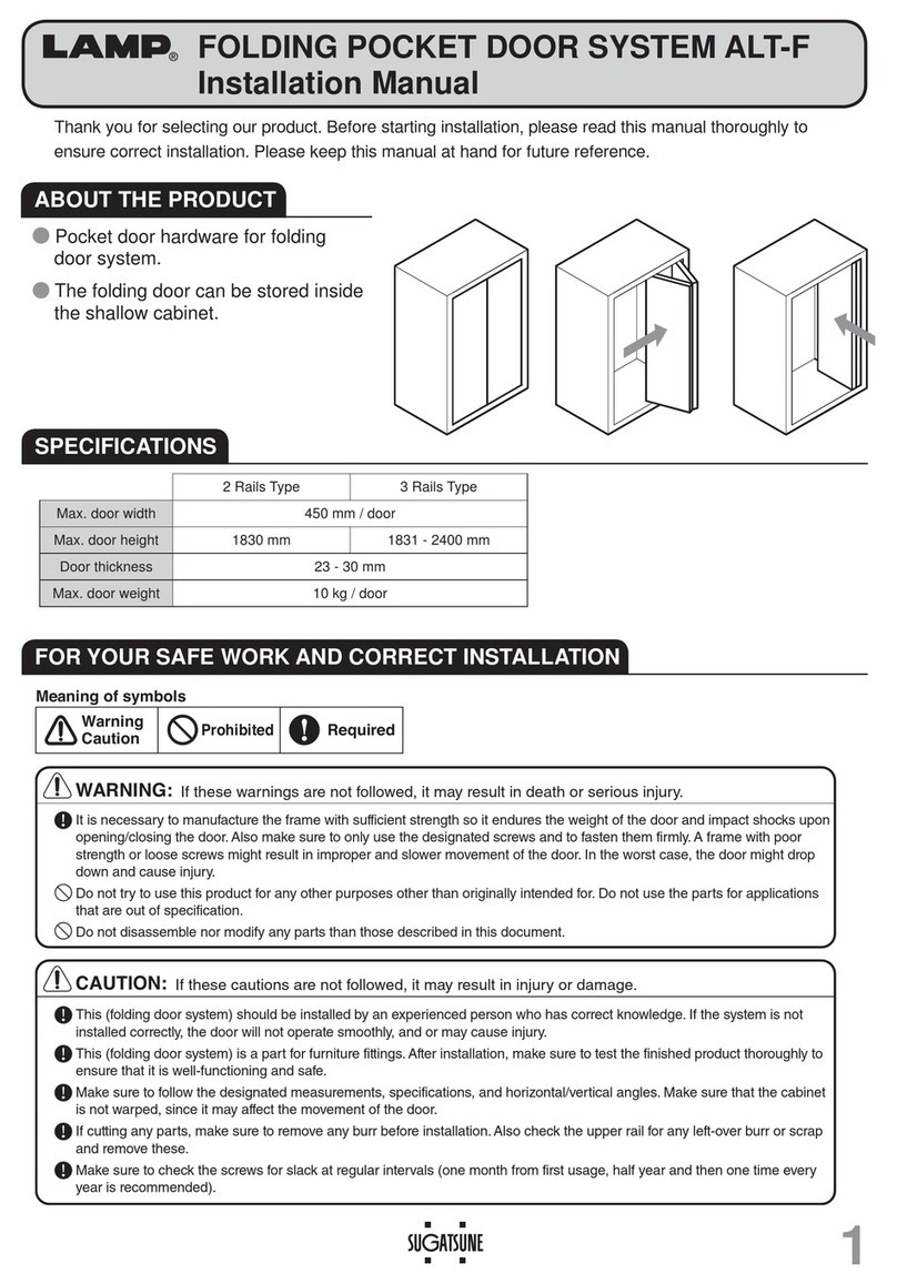
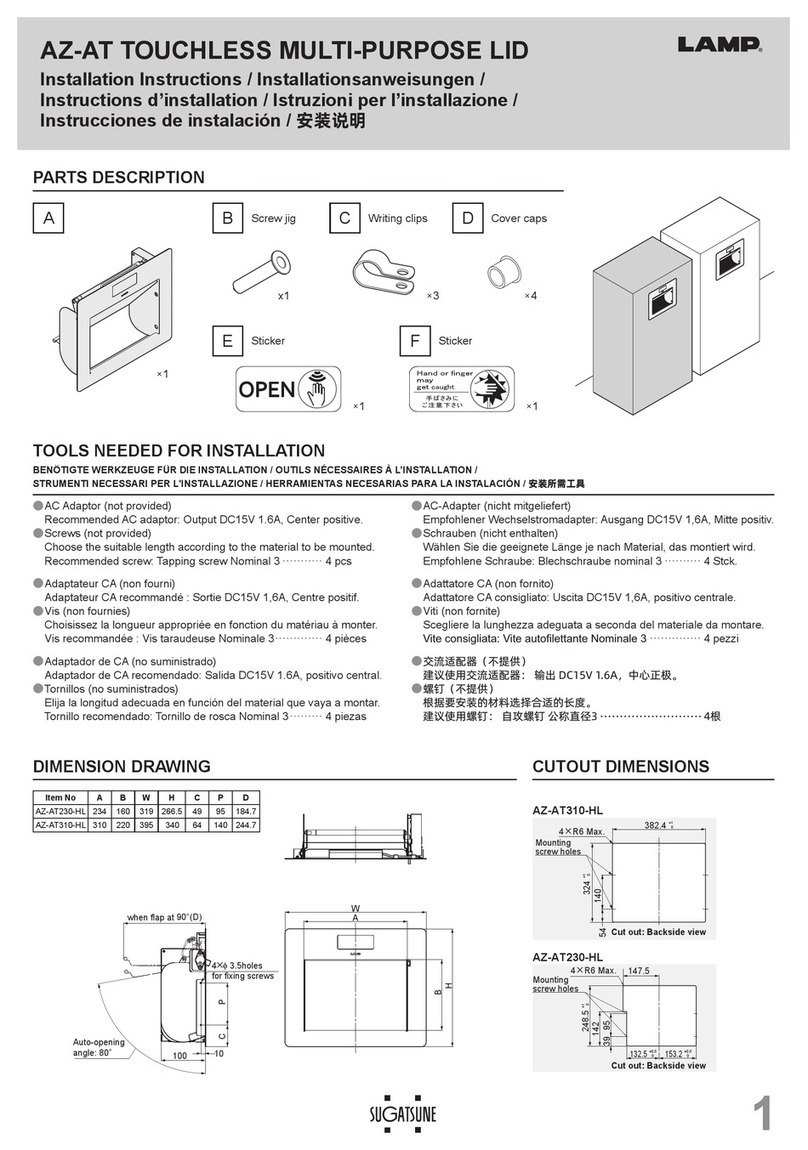
The dimensions in case of the 90°opening door are shown in the following figures. The dimensions in case of the 80°opening door are shown in ( ).
MOUNTING DIMENSIONS
■Type selection method
Cautions for operation
Keep a door from forced opening and closing. It is prohibited to open a door over a full open angle or to close a door with excess force.
The working temperature range of this mechanism is 5~35°C. Opening and closing speed of the door depends on the temperature.This is not
the symptom of troubles. It is prohibited to use this mechanism at the temperature exceeding the specified range. It is not permitted to apply this
mechanism for the cabinet installing a heat-generating microwave oven or other similar appliances.
Be careful not to insert a finger into the arm mechanism of the unit. Sever injury may be caused.
It is necessary to periodically check the fixing screws for loosing. Tighten the loosed screws as required.
●
●
●
●
●
●
●
●
●
The right-hand and left-hand side bodies of this mechanism should be installed in set.
This is the mechanism exclusively for a flap type door application. Be reminded that we can not take the responsibility for damages and injuries caused
by other applications, disassembly, conversion and the application to the door exceeding the standard ranges shown in the item ”Type selection meth-
od”.
This mechanism must be installed to the cabinet correctly in accordance with the indications of this manual. Notice that the non-observance of the
specified dimensions not only does not enable this mechanism to show its full performance, but also may result in damage and also cause injury.
It is necessary to use the attached screws for installing this mechanism. Otherwise the disconnection of this mechanism may happen causing injury.
For improvement the specification may be changed without notice. As for details please verify the actual goods.
The applicable door must have the construction for which it is difficult to induce bent or torsion.
Any failure to observe the following cautions may result in personal injury and property damage.
CAUTION
Cautions for installation Fig. 7
Hinge center for slide hinge
(dimension standard plane)
S
A=134
ー
D
B=15+T
ー
0
W=Cabinet overall width
0
T=Cabinet side board thickness
W=Door width
S=Overlay
C=Distance from the side board inside surface
to the aluminum frame side surface
1
0
)
1
0
W
ー
W
(2
C(1〜4mm)
Rubber gasket thickness D (3-5 is recommended)
16
Glass
5.5 (from the door inside plane)
6
20
50
Side board
Aluminum frame
9
B
(from the door
side end plane)
32
Fig. 8
A
157.5
ー
S
(167
ー
S)
173.5
ー
S
(183
ー
S)
32
115(124.5)
Step 4
Step 7
Step 5
Step 6
Bind tapping screw 3.5x15
(Tighten 4 screws of Step 2 and Step 7)
Truss screw M4x6
5
6
Truss screw M4x6
8
Fig. 10
※Screws for fixing
mounting plate are NOT
included.
Prepare 2 pcs of screw
separately. (M3.5~4 is recommended.)
Parts for installing to 20mm width aluminum frame door
7
5
Bind tapping screw
(3.5x15) 4pcs
6
4
HDSN-SZ mounting
plate 1pc Truss screw (M4x6)
1pc
1
8
HDSN-AZ mounting
plate 1pc
Parts of separate packing (Select either)
HDSN-30 body / left-hand side 1pc
2
Body mounting plate 1pc 3
Bind tapping screw
(3.5x15) 3pcs
Truss screw (M4x6)
1pc
PAT.P
R
1
HDSN-30 body / right-hand side 1pc
2
Body mounting plate 1pc 3
Bind tapping screw
(3.5x15) 3pcs
PAT.P
R
Parts for installing to 45mm width
aluminum frame door or solid wooden door Option Option
2 pcs
Door
Bind tapping screw 3.5x15
3.5×15 Step 2
Step 1
Step 3
Bind tapping screw
(Oblong hole for temporary fixing)
HDSN-30 body
Door
HDSN-SZ
Side board
Body mounting
plate
1
36
4
2
Fig. 9
(Prepare separately)
Screws for fixing the mounting plate
HDSN-AZ
7
The slide hinge (overlay use, non-catch type) should be used as a
door- hanging device.
The LAMP brand 220 series slide hinge (product No. 220-26/19T,
non-catch type) is recommended.
Fig. 3
Fig. 2. Cabinet
Step 1.Place the mounting plate ②to the specified position of the inside surface of
a cabinet and fix it with the attached bind tapping screws 3.5x15 ③firmly.
Step 2.
●In case of HDSN-SZ mounting plate (for 45mm width
aluminum frame door or solid wooden door)
Temporarily fix the HDSN-SZ mounting plate ④through its oblong hole to the
specified position of the back of the door with the attached bind tapping screws
3.5x15 ⑥.
●In case the HDSN-AZ mounting plate (for 20mm width
aluminum frame door)
The fixing screws are not supplied. Prepare them separately (M3.5-4 is
recommended).Fix the HDSN-AZ mounting plate ⑦with the prepared fixing
screws firmly. (Fig. 7 and 9)
※The HDSN-AZ mounting plate ⑦should be mounted so that the distance (C)
between the side board inside surface and the aluminum frame side surface be
in the range of 1~4mm. (Fig. 8)
This drawing shows the case of installation to 45mm width aluminum frame door or solid wooden door (HDSN-SZ). As for the case of installation to
20mm width aluminum frame door (HDSN-AZ), refer to Fig. 7 and 8.
H
T
W
1
0
W
0
Step 3.Put the hole of the HDSN-30 side body ①to the axis of the body mounting
plate ②, insert the unit body up to the root of the plate making click.
Never use a hammer or others like it in order to insert the mounting plate
into the HDSN-30 body ①. Otherwise trouble or damage may happen.
Step 4. Adjusting the axis of the HDSN-SZ mounting plate ④and the hole in the
arm end, insert the truss screw M4x6 ⑥.
Step 5.
Check the door opening and closing function and adjust the position of the
HDSN-SZ mounting plate ④through its oblong hole.
Step 6.
Remove the arm from the mounting plate. Then, fix the plate firmly with the
bind tapping screw ⑥into its circular hole.
Step 7.
Insert the arm into the axis of the mounting plate again and fix the arm firmly
with the truss screw M4x6 ⑤. (Fig. 10)
Fig. 4
This shows the installation procedure for the application of 45mm width aluminum frame door or solid wooden door (HDSN-SZ).
In case of the installation procedure for the application of 20mm width aluminum frame door (HDSN-AZ), refer to Fig. 9 and 10.
Fig. 5 Fig. 6
Before installing the unit, mount the slide hinge to the specified position and adjust it so that the door can be opened and closed smoothly.
The position adjustment of the slide hinge should be carried out before installing the HDSN-SZ or HDSN-AZ mounting plate. Otherwise the stay arm may be deflected right or left as
shown in Fig. 6, which may result in trouble or damage.
Lapcon is an innovative technology developed and designed for ultimate shock absorption
and the smoothest opening and closing movement imaginable.
HDSN-30 HEAVY-DUTY SOFT-DOWN STAY
INSTALLATION MANUAL PAT.P
Read this manual carefully for proper installation and operation.
Incorrect installation and improper use of the product may cause damage to the unit and also cause injury.
This manual should be kept by the user after installation.
Lapcon mount-on series
Fig. 1. Part description
■
Part description
Calculate the door torque according to the following formula considering the weight and the
height of the applicable door. Select the suitable type as per Table 1.
Type Door torque
Opening angle 90° Opening angle 80°
HDSN-30K
13.7 〜17.5 N・m ( 140 〜189 kgf・
cm ) 13.7 〜19.5 N・m ( 140 〜199 kgf・
cm )
HDSN-30M
17.6 〜21.5 N・m ( 190 〜229 kgf・
cm ) 19.6 〜24.4N・m ( 200 〜249 kgf・
cm )
HDSN-30H
21.6 〜25.4N・m ( 230 〜269 kgf・
cm ) 24.5 〜29.3N・m ( 250 〜299 kgf・cm )
HDSN-30S
25.5 〜29.4 N・m ( 270 〜300 kgf・
cm ) 29.4 〜34.3 N・m ( 300 〜350 kgf・cm )
※Contact our sales representatives in case of installing to a cabinet exceeding the
indicated ranges.
Door height (m) /2 x Door weight (kg) x 9.8 = Door torque (N_m)
Table 1. Type and suitable door range
■INSTALLATION PROCEDURE
1-8-11 HigashiKanda, Chiyoda-ku,
Tokyo 101-8633, Japan
TEL:+81-3-3866-2260 FAX:+81-3-3866-4447
http://www.sugatsune.co.jp
For Overseas Customers
SUGATSUNE KOGYO CO., LTD.
ISO9001(JSAQ384)・ISO14001(JSAE597) CERTIFICAT.
221 East Selandia Lane,
Carson,CA 90746,U.S.A.
TEL:+1-310-329-6373 FAX:+1-310-329-0819
TOLL FREE:(800) 562-5267 (from U.S.A & Canada only)
http://www.sugatsune.com
For North American Customers
SUGATSUNE AMERICA, INC.
12.2004SEPRINTEDINJAPAN 0255-1


