PHW/PHWS SERIES PRESSURE WASHER
OPERATOR’S MANUAL
7
❑Grip spray gun and wand handle securely.
❑On PHW models, turn the pump and burner switch to
the pump position.
On PHWS models, turn the pump and burner switch
ON and then pull the trigger on the spray gun to acti-
vate a pressure switch which will then start the ma-
chine.
When a steady stream of water flows from the spray
gun and wand, turn the thermostat knob to the 200°
mark, then push the burner switch (PHWS models) or
turn the pump and burner switch (PHW models) to
the burner position. The burner will light automatically
when the spray gun trigger is pulled. On the PHWS
models, the ignition light should be illuminated.
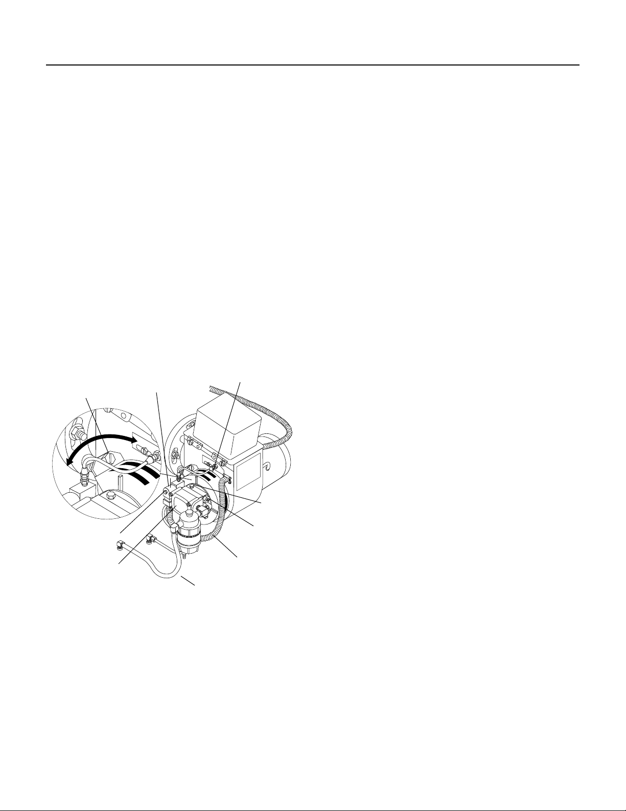
❑Turn the variable pressure control handle clockwise
to increase pressure.
❑Place chemical hose into chemical container and open
chemical valve. NOTE: Do not run this machine more
than five minutes with spray gun closed. When spray
gun is closed more than two minutes, the pump pro-
tector on PHW models will open to allow hot water to
dump on the ground; thus allowing cold water to re-
enter the pump. On PHWS models, a time delay fea-
ture will shut the machine off.
SHUT DOWN PROCEDURES
❑Place chemical line in a bucket of water allowing
chemical to be flushed from system.Then turn chemi-
cal valve off.
❑Push burner switch off or turn switch to pump position
and open trigger on spray gun, allowing water to flow,
which will cool down the heating coil.
❑After water has cooled, turn the pump and burner
switch to the OFF position (PHW models). On PHWS
models, release the trigger on the spray gun which
will activate a timer to shut the machine off after one
minute. On PHWS models, turn the pump switch off if
the machine is going to be left unattended.
❑Turn water off.
❑Protect from freezing (see Winterizing Procedures).
GENERAL WASHING
TECHNIQUES
This machine is equipped with a spray gun and various
nozzle patterns, use the wide patterns on easy soil re-
moval jobs and the narrow patterns on the more difficult
jobs or tight areas such as cracks and holes.
PRE-OPERATION CHECK
❑Check pump oil level. (Use SAE 30W non-detergent
oil). Dipstick is located on top of pump.
❑Cold water supply (minimum 6 gpm, 5/8", 20 psi)
❑Hose, wand, nozzle (nozzle size per serial plate)
❑Water filter (intact, non restrictive)
❑Open spray gun to relieve pressure before starting.
SET-UP PROCEDURES
These machines are intended for indoor use.
Machines must be stored indoors when not in use.
❑Location of machine is important. Avoid installing near
combustible material or in poorly ventilated areas.
❑Electrical connection to machine should be the proper
voltage, phase and amperage. See specifications for
particular model. Plug the power cord into a grounded
receptacle. The PHW2-11021D, PHW3-11021D and
PHWS3-11021D each require a 20 amp receptacle
to comply with UL 1776 standards.
❑Water source for machines should be supplied by a
5/8" I.D. garden hose with a city water pressure of not
less than 30 PSI. If the water supply is inadequate, or
if the garden hose is kinked, the machine will run very
rough and the burner will not fire.
❑Fill fuel tank with proper fuel.
❑Adding exhaust vent pipe to your oil fired burner is not
recommended because it restricts air flow.This causes
carbon build-up, which affects the operation and in-
creases maintenance on the coil. If a stack must be
used, refrain from using 90 degree bends. If the pipe
can not go straight up then use only 45 degree bends
and go to the next larger size pipe. The overall pipe
length must not exceed 6 feet in length
OPERATING INSTRUCTIONS
❑Read safety, installation and preventative maintenance
instructions before starting machine.
❑Connect the water supply hose to the float tank inlet
swivel connector and turn on water supply.
❑Check fuel tank level.
❑Connect the high pressure hose quick coupler to dis-
charge nipple by sliding the quick coupler collar back
and inserting quick coupler on coupler nipple and push-
ing the quick coupler collar forward to secure it.
❑Connect the wand, nozzle, hose and spray gun (where
applicable). Use teflon tape on pipe thread connec-
tions to avoid water leaks (see component identifica-
tion).
❑Plug the power cord into the proper power supply. (Re-
fer to serial plate for information.)