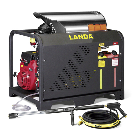
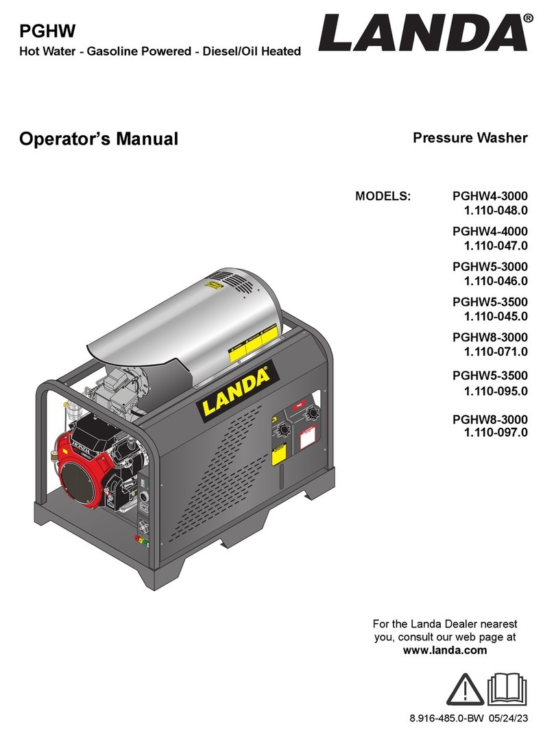
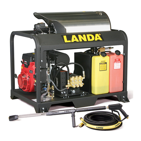
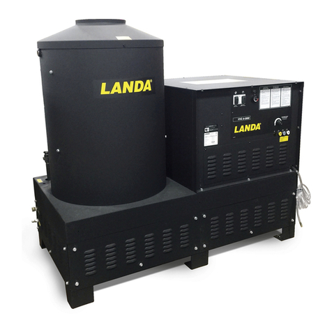
Landa Pgdc5-3500 User manual

8.916-596.0 - BF 01/15/21
PGDC
Hot Water - Gasoline Powered - Diesel/Oil Heated
Operator’s Manual Pressure Washer
GAS
8.916-274.0
DIESEL
8.932-960.0
MODELS:
PGDC4 - 3500
1.110-049.0
PGDC5 - 3500
1.110-050.0
PGDC5 - 3500
1.110-051.0
PGDC8 - 3000
1.110-072.0
For the Landa Dealer nearest
you, consult our web page at
www.landa.com

2Landa PGDC Operator’s Manual 8.916-596.0 - BF
Machine Data Label

3
Table of Contents
Machine Data Label . . . . . . . . . . . . . . . . . . . . . . . . . .2
Table of Contents . . . . . . . . . . . . . . . . . . . . . . . . . . .3
How To Use This Manual . . . . . . . . . . . . . . . . . . . . .4
Safety
Introduction & Safety Information . . . . . . . . . . . . . . .5
Important Safety Information. . . . . . . . . . . . . . . . . . .5
Operations
Component Identification . . . . . . . . . . . . . . . . . . . . .9
Assembly Instructions . . . . . . . . . . . . . . . . . . . . . . .10
Battery Installation . . . . . . . . . . . . . . . . . . . . . . . . .10
Operation Instructions. . . . . . . . . . . . . . . . . . . . . . .11
Detergents & General Cleaning Techniques . . . . .12
Shutting Down And
Clean-up . . . . . . . . . . . . . . . . . . . . . . . . . . . . . . .13
Maintenance
Storage . . . . . . . . . . . . . . . . . . . . . . . . . . . . . . . . . .14
Engine Maintenance . . . . . . . . . . . . . . . . . . . . . . . .14
Burner Air Adjustment. . . . . . . . . . . . . . . . . . . . . . .17
Troubleshooting . . . . . . . . . . . . . . . . . . . . . . . . . . . 18
Preventative Maintenance . . . . . . . . . . . . . . . . . . .22
Maintenance Schedule . . . . . . . . . . . . . . . . . . . . . . 22
Oil Change Record . . . . . . . . . . . . . . . . . . . . . . . . . 23
Parts
Landa PGDC. . . . . . . . . . . . . . . . . . . . . . . . . . . . . 26
Power Platform . . . . . . . . . . . . . . . . . . . . . . . . . . . 30
Control Box . . . . . . . . . . . . . . . . . . . . . . . . . . . . . . 33
Coil . . . . . . . . . . . . . . . . . . . . . . . . . . . . . . . . . . . . 34
Option, Float Tank . . . . . . . . . . . . . . . . . . . . . . . . 36
Hose & Spray Gun . . . . . . . . . . . . . . . . . . . . . . . . 38
Burner . . . . . . . . . . . . . . . . . . . . . . . . . . . . . . . . . . 39
Unloader - 4-3500, 5-3500 . . . . . . . . . . . . . . . . . . 40
Unloader - 8-3000 . . . . . . . . . . . . . . . . . . . . . . . . . 41
Pump. . . . . . . . . . . . . . . . . . . . . . . . . . . . . . . . . . . 42
Specifications . . . . . . . . . . . . . . . . . . . . . . . . . . . . 44
PGDC Series Wayne “EHASR-DC” Burner . . . . . 45
LT.2 Series Pump . . . . . . . . . . . . . . . . . . . . . . . . . 46
VRT3 Unloader . . . . . . . . . . . . . . . . . . . . . . . . . . . 48
Landa PGDC Operator’s Manual 8.916-596.0 - BF

4
How To Use This Manual
This manual contains the following sections:
• How to Use This Manual
•Safety
• Operations
• Maintenance
• Parts List
The HOW TO USE THIS MANUAL section will tell you
how to find important information for ordering correct
repair parts.
Parts may be ordered from authorized dealers. When
placing an order for parts, the machine model and
machine serial number are important. Refer to the
MACHINE DATA box which is filled out during the
installation of your machine. The MACHINE DATA box
is located on the inside of the front cover of this manual.
The model and serial number of your machine is
located on the back of the machine.
The SAFETY section contains important information
regarding hazardous or unsafe practices of the
machine. Levels of hazards are identified that could
result in product damage, personal injury, or severe
injury resulting in death.
The OPERATIONS section is to familiarize the operator
with the operation and function of the machine.
The MAINTENANCE section contains preventive main-
tenance to keep the machine and its components in
good working condition. They are listed in this general
order:
• Storage
• Engine Maintenance
• Landa Sure Fire Oil Burner
• Troubleshooting
• Preventative Maintenance
• Oil Change Record
The PARTS LIST section contains assembled parts
illustrations and corresponding parts list. The parts lists
include a number of columns of information:
•REF – column refers to the reference number
on the parts illustration.
•PART NO. – column lists the part number for
the part.
•QTY – column lists the quantity of the part used
in that area of the machine.
•DESCRIPTION – column is a brief description
of the part.
•NOTES – column for information not noted by
the other columns.
NOTE: If a service or option kit is installed on your
machine, be sure to keep the KIT INSTRUCTIONS
which came with the kit. It contains replacement parts
numbers needed for ordering future parts.
NOTE: The manual part number is located on the
lower right corner of the front cover.
Model:
Date of Purchase:
Serial Number:
Dealer:
Address:
Phone Number:
Sales Representative:
Landa PGDC Operator’s Manual 8.916-596.0 - BF

5
Safety
Introduction & Safety Information
Thank you for purchasing this Pressure Washer. We
reserve the right to make changes at any time
without incurring any obligation.
Owner/User Responsibility:
The owner and/or user must have an understanding of
the manufacturer’s operating instructions and warnings
before using this pressure washer. Warning information
should be emphasized and understood. If the operator
is not fluent in English, the manufacturer’s instructions
and warnings shall be read to and discussed with the
operator in the operator’s native language by the
purchaser/owner, making sure that the operator
comprehends its contents.
Owner and/or user must study and maintain for future
reference the manufacturers’ instructions.
The operator must know how to stop the machine
quickly and understand the operation of all controls.
Never permit anyone to operate the engine without
proper instructions.
SAVE THESE INSTRUCTIONS
This manual should be considered a permanent
part of the machine and should remain with it if
machine is resold.
When ordering parts, please specify model and
serial number. Use only identical replacement
parts.
This machine is to be used only by trained opera-
tors.
Important Safety Information
WARNING: To reduce the risk of
injury, read operating instructions
carefully before using.
AVERTISSEMENT: Pour réduire le
risque de blessures, lire attentive-
ment les instructions de
fonctionnement avant l'utilisation
1. Read the owner's manual thor-
oughly. Failure to follow instruc-
tions could cause malfunction of the machine and
result in death, serious bodily injury and/or property
damage.
2. Know how to stop the machine and bleed pressure
quickly. Be thoroughly familiar with the controls.
3. Stay alert — watch what you are doing.
DANGER: Keep wand, hose, and
water spray away from electric
wiring or fatal electric shock may
result.
DANGER: Garder la lance, le
boyau et le jet d'eau à l'écart de
tout câblage électrique ou des
chocs électriques mortels
pourraient survenir.
4. All installations must comply with local codes.
Contact your electrician, plumber, utility company
or the selling distributor for specific details.
Landa PGDC Operator’s Manual 8.916-596.0 - BF
WARNING
READ OPERATOR’S
MANUAL THOROUGHLY
PRIOR TO USE.
OPERATIONS
SAFETY
MAINTENANCE
DANGER
KEEP WATER
SPRAY AWAY FROM
ELECTRICAL WIRING.

6
Safety
WARNING: This machine exceeds
85 db appropriate ear protection
must be worn.
AVERTISSEMENT: Cette machine
excède XX dB et une protection
de l'ouïe appropriée doit être
portée
WARNING: High pressure spray
can cause paint chips or other
particles to become airborne and
fly at high speeds. To avoid
personal injury, eye, hand and
foot safety devices must be worn.
AVERTISSEMENT: Un jet haute
pression peut écailler la peinture
ou provoquer l'émission d'autres
particules dans l'air et leur projection à hautes
vitesses. Pour éviter les lésions corporelles, une
protection des yeux, du visage, des mains et des
pieds doit être portée lors de l'utilisation de cet
équipement
1. Always wear properly rated eye protection such as
safety goggles or face shield while
spraying.
(Safety glasses do not provide full protection.)
2. Keep operating area clear of all persons.
WARNING: Flammable liquids can create fumes
which can ignite, causing property damage or
severe injury.
AVERTISSEMENT: Des liquides inflammables
peuvent produire des vapeurs qui peuvent
s'enflammer, causant ainsi des dommages à la
propriété ou des blessures graves.
WARNING: Risk of explosion —
Operate only where open flame or
torch is permitted.
AVERTISSEMENT: Risque d'explo-
sion - Utiliser uniquement dans
des endroits où l'utilisation d'une
flamme nue ou d'une torche est
permise.
WARNING: Risk of fire — Do not
add fuel when the machine is
operating or still hot.
AVERTISSEMENT: Risque
d'incendie-Ne pas ajouter de
carburant pendant que la machine
fonctionner ou est encore chaude.
WARNING: Do not use gasoline
crankcase drainings or oil
containing gasoline, solvents or alcohol. Doing so
will result in fire and/or explosion.
AVERTISSEMENT: Ne pas utiliser d'essence, de
drainage du carter de moteur ou d'essence
contenant de l'huile, de solvants ou de l'alcool.
WARNING: Risk of fire — Do not
Spray flammable liquids.
AVERTISSEMENT: Risque
d'incendie- Ne pas pulvériser de
liquides inflammables
3. Allow engine to cool for 1-2
minutes before refueling. If any
fuel is spilled, make sure the
area is dry before testing the
spark plug or starting the engine. (Fire and/or
explosion may occur if this is not done.)
Gasoline engines on mobile or portable equipment
shall be refueled:
a. outdoors;
b. with the engine on the equipment stopped;
c. with no source of ignition within 10 feet of the
dispensing point; and
d. with an allowance made for expansion of the
fuel should the equipment be exposed to a
higher ambient temperature.
In an overfilling situation, additional precautions
are necessary to ensure that the situation is
handled in a safe manner.
WARNING: Risk of injury. Disconnect battery
ground terminal before servicing.
AVERTISSEMENT: Risque de blessures.
Débrancher la borne de mise à la terre de la batterie
avant de procéder à des opérations d'entretien
4. When in use, do not place machine near
flammable objects as the engine is hot.
5. Oil burning appliances shall be installed only in
locations where combustible dusts and flammable
Landa PGDC Operator’s Manual 8.916-596.0 - BF
WARNING
EAR PROTECTION
MUST BE WORN
WARNING
USE PROTECTIVE
EYE WEAR
AND CLOTHING
WHEN OPERATING
THIS EQUIPMENT.
WARNING
RISK OF EXPLOSION:
OPERATE ONLY WHERE
OPEN FLAME OR TORCH
IS PERMITTED
WARNING
RISK OF FIRE.
DO NOT ADD FUEL
WHEN OPERATING
MACHINE.
WARNING
RISK OF FIRE.
DO NOT SPRAY
FLAMMABLE LIQUIDS

7
Safety
gases or vapors are not present. Do not store or
use gasoline near this machine.
6. Use No. 1 or No. 2 heating oil (ASTM D306) only.
NEVER use gasoline in your fuel oil tank. Gasoline
is more combustible than fuel oil and could result in
a serious explosion. NEVER use crankcase or
waste oil in your burner. Fuel unit malfunction could
result from contamination.
7. Do not confuse gasoline and fuel oil tanks. Keep
proper fuel in proper tank.
WARNING: Risk of injury. Hot
surfaces can cause burns. Use
only designated gripping areas of
spray gun and wand. Do not place
hands or feet on non-insulated
areas of the pressure washer.
AVERTISSEMENT: Risque de
blessures. Les surfaces chaudes
peuvent causer des brûlures.
Utiliser uniquement les zones de
prise désignées du pistolet pulvérisateur et de la
lance. Ne pas placer les mains ou les pieds sur des
endroits non isolés de la laveuse à pression
8. Transport/Repair with fuel tank EMPTY or with fuel
shut-off valve OFF.
CAUTION: Hot discharge fluid. Do
not touch or direct discharge
stream at persons or animals.
ATTENTION: Liquide de décharge
chaud. Ne pas toucher ou
décharger directement le jet vers
des personnes ou des animaux
WARNING: This machine produces hot water and
must have insulated components attached to
protect the operator.
AVERTISSEMENT: Cette machine produit de l'eau
chaude et doit comporter des composants isolés
attachés pour protéger l'opérateur
9. To reduce the risk of injury, close supervision is
necessary when a machine is used near children.
Do not allow children to operate the pressure
washer. This machine must be attended during
operation.
WARNING: Grip cleaning wand
securely with both hands before
starting. Failure to do this could
result in injury from a whipping
wand.
AVERTISSEMENT: Agripper la
lance de nettoyage avec les deux
mains avant de commencer. Le
non-respect de cette consigne
pourrait mener à des blessures
causées par le mouvement violent de la lance
10. Never make adjustments on machine while in
operation.
Be certain all quick coupler fittings are secured
before using pressure washer.
WARNING: High pressure
developed by these machines will
cause personal injury or
equipment damage. Keep clear of
nozzle. Use caution when oper-
ating. Do not direct discharge
stream at people and animals, or
severe injury or death will result.
AVERTISSEMENT: La haute
pression générée par ces machines causera des
lésions corporelles ou des dommages à
l'équipement.
Se tenir à l'écart de la buse. Faire preuve de
prudence lors de l'utilisation. Ne pas décharger
directement le jet vers des personnes ou des
animaux, car cela risquerait de causer des
blessures graves ou même la mort.
WARNING: Protect machine from
freezing.
AVERTISSEMENT: Protéger la
machine contre le gel.
11. To keep machine in best
operating conditions, it is
important you protect machine
from freezing. Failure to protect
machine from freezing could
cause malfunction of the machine and result in
death, serious bodily injury, and/or property
damage. Follow storage instructions specified in
this manual.
12. Inlet water must be clean fresh water and no hotter
then 90°F.
Landa PGDC Operator’s Manual 8.916-596.0 - BF
WARNING
RISK OF INJURY.
HOT SURFACES
CAN CAUSE BURNS
WARNING
HOT DISCHARGE FLUID:
DO NOT TOUCH OR
DIRECT DISCHARGE
STEAM AT PERSONS.
WARNING
TRIGGER GUN KICKS
BACK — HOLD WITH
BOTH HANDS
WARNING
RISK OF INJECTION
OR SEVERE INJURY
TO PERSONS. KEEP
CLEAR OF NOZZLE.
WARNING
PROCTECT FROM
FREEZING
8
Safety
DANGER: Risk of asphyxiation.
Running this product indoors can
result in death due to carbon
monoxide, poison gas you cannot
see or smell. Only use outdoors
and far away from windows,
doors, and openings or vents. Use
this product only in a well venti-
lated area.
DANGER: Risque d'asphyxie.
L'utilisation de ce produit à l'intérieur peut causer
la mort par monoxyde de carbone, un gaz toxique
incolore et inodore. Utiliser uniquement à
l'extérieur et à l'écart des fenêtres, des portes et
des ouvertures ou fentes de ventilation. Utiliser ce
produit uniquement dans un endroit bien ventilé.
13. Avoid installing machines in small areas or near
exhaust fans. Adequate oxygen is needed for
combustion or dangerous carbon monoxide will
result.
14. Manufacturer will not be liable for any changes
made to our standard machines or any compo-
nents not purchased from us.
15. The best insurance against an accident is precau-
tion and knowledge of the machine.
WARNING: Be extremely careful
when using a ladder, scaffolding
or any other relatively unstable
location. The cleaning area should
have adequate slopes and
drainage to reduce the possibility
of a fall due to slippery surfaces.
AVERTISSEMENT: Faire preuve
d'une extrême prudence au
moment d'utiliser une échelle, des
échafaudages ou toute autre surface relativement
instable. La zone de nettoyage doit avoir une pente
et un drainage adéquats pour réduire la possibilité
d'une chute due à une surface glissante
16. Do not allow acids, caustic or abrasive fluids to
pass through the pump.
17. Never run pump dry or leave spray gun closed
longer than 1-2 minutes.
18. Machines with shut-off spray gun should not be
operated with the spray gun in the off position for
extensive periods of time as this may cause
damage to the pump.
19. Protect discharge hose from vehicle traffic and
sharp objects. Inspect condition of high pressure
hose before using or bodily injury may result.
20. Before disconnecting discharge hose from water
outlet, turn burner off and open spray gun to allow
water to cool below 100° before stopping the
machine. Then open the spray gun to relieve
pressure. Failure to properly cool down or maintain
the heating coil may result in a steam explosion.
21. Do not overreach or stand on unstable support.
Keep good footing and balance at all times.
22. Do not operate this machine when fatigued or
under the influence of alcohol, prescription medica-
tions, or drugs.
23. In oil burning models, use only kerosene, No. 1
home heating fuel, or diesel. If diesel is used, add a
soot remover to every tankful.
WARNING: Do not spray machine
or any people, animals or elec-
trical parts.
AVERTISSEMENT: Ne pas
vaporiser sur la machine ou les
gens, les animaux ou les pièces
électriques
WARNING: If connection is made
to a potable water system, the
system shall be protected against
back flow.
AVERTISSEMENT: Si une
connexion est établie avec un
approvisionnement en eau
potable, un dispositif de protec-
tion contre le retour d'eau doit
être fourni.
Follow the maintenance instructions
specified in the manual.
Landa PGDC Operator’s Manual 8.916-596.0 - BF
WARNING
DO NOT SPRAY
MACHINE OR ANY
PEOPLE, ANIMALS OR
ELECTRICAL PARTS.
WARNING
IF CONNECTED
TO A POTABLE
WATER SUPPLY,
PROTECT AGAINST
BACKFLOW.
RISK OF
ASPHYXIATION.
USE THIS PRODUCT
ONLY IN A WELL
VENTILATED AREA.
DANGER
WARNING

RISK OF INJURY
FROM FALLS WHEN
USING LADDER.

9
Operations
Component Identification
Landa PGDC Operator’s Manual 8.916-596.0 - BF
GA S
8.916-274.0
DIESEL
8.932-960.0
Detergent
Pick Up
Tube
Water Supply
Hose (not
included)
Detergent
Bucket
(not included)
High Pressure
Hose
Fuel Oil
Tank
Variable
Pressure
Control
Wand Handle
Variable Pressure
Control Wand
Nozzle
Engine
Switch
Spray
Gun
Nozzle
Quick
Coupler
Discharge
Nipple
Rupture
Disk
Gasoline
Tank
Pressure
Nozzles
Burner
Switch
Trigger
Fresh
Water
Inlet
Detergent
Injector
(not included)
Trigger
Safety Latch

10
Operations
Assembly Instructions
STEP 1: Attach a 5/8" water supply
hose to inlet connector. Minimum
flow should be 6 or 10 gpm
depending on model of machine.
STEP 4: Check engine and pump
oil level by removing oil dipstick,
making sure oil is on proper
indicator marking. Oil should be
visible one half way up sight glass
located at the end of pump
(SAE 10W-40 non-foaming).
STEP 2: Attach wand to spray gun
using teflon tape on threads to
prevent leakage. Attach swivel
connector on discharge hose to
spray gun using teflon tape on
threads. Attach swivel connector on
high pressure hose to spray gun
using teflon tape on threads.
Engage safety latch to prevent from
triggering gun when inserting high
pressure nozzle.
STEP 5: Fill red gasoline tank. Fill
green fuel oil tank. Do not confuse
gasoline and fuel oil (diesel) tanks.
Keep proper fuel in proper tank.
STEP 3: Attach high pressure hose
to discharge nipple using quick
coupler. Lock coupler securely into
place by pulling back coupler collar
and inserting it into discharge
nipple, then pushing collar forward
to lock in place.
STEP 6: Install proper battery
making sure that the red cable is
attached to the positive terminal.
Use a 12V Group 24 battery on all
models except 4-40321 and 5-
35321E. These models use a U1
30 amp garden tractor style battery.
Landa PGDC Operator’s Manual 8.916-596.0 - BF
Spray Wand
Safety
Latch
Spra
y
Gun
High Pressure
Hose
GAS
8.916-274.0
DIESEL
8.932-960.0
High
Pressure
Hose
Discharge
Nipple
GAS
8.916-274.0
DIESEL
8.932-960.0
Gasoline
Burner Fuel
Battery Installation
Due to Federal Regula-
tions concerning shipment
of corrosive chemicals,
batteries are not shipped
with this machine.
Local purchase of battery will be the responsibility of
the owner. Automotive type 12 Volt Group 24 battery is
recommended for placement within the weather
resistant box. Follow safety and installation instructions
furnished with the battery.
Red Cable is attached to battery (+) positive terminal,
black cable is connected to battery (-) negative
terminal.
SHIELD
EYES
EXPLOSIVE
GASES CAN CAUSE
BLINDNESS OR INJURY
NO
SPARKS
FLAMES
SMOKING
SULFURIC
ACID
CAN CAUSE
BLINDNESS OR
SEVERE BURNS
FLUSH EYES
IMMEDIATELY
WITH WATER
GET
MEDICAL
HELP
FAST
KEEP OUT OF THE REACH OF CHILDREN. DO NOT TIP
. KEEP VENT CAPS TIGHT AND LEVEL.
DANGER
/
POISON
Bla
ck - Negative
T
erminal
Red + Positive
Terminal
Blac
k
Red

11
Operations
Operation Instructions
STEP 1: Read operator’s manual
before operating. Pull wand coupler
collar back, insert desired pressure
nozzle into coupler, then secure by
pushing collar forward.
CAUTION: Never replace nozzles
without engaging the safety
latch on the spray gun trigger.
ATTENTION: Ne jamais
remplacer les buses sans
d'abord mettre le dispositif de
sécurité sur la détente du
pistolet pulvérisateur.
STEP 4: With the spray nozzle
pointed away from you or anybody
else, press the trigger on the spray
gun to obtain pressurized cold
water spray.
STEP 2: Turn on water at faucet
and pull trigger on spray gun
allowing water to flow until all air
has discharged from system.
Check for water leaks; tighten as
needed. NOTE: Variable pressure
control wand handle must be
turned clockwise to enable water to
flow out of the high pressure
nozzle.
STEP 5: For hot water, turn the
burner switch to ON when a steady
stream of water flows out of the
spray gun. Burner will now light
automatically. NOTE: Do not start
machine with burner switch on.
STEP 3: Read engine manual. Move
fuel valve to closed or OFF position,
if equipped. To start engine, if choke
is closed, gradually move it to the
open position as the engine warms
up. Turn the engine switch to the
START position and hold it there until
the engine starts.
NOTE: Do not use the electric starter
for more than five seconds at a time.
If the engine fails to start, release the
switch and wait ten seconds before
operating the starter again. When the
engine starts, allow the engine switch
to return to the ON position. If the
engine is to be started without the
battery, turn switch to start position
and pull rope to start. Turn off choke.
WARNING: Small engines may
kick back. Do not hold pull rope
tightly in hand. Starter cord
kickback (rapid retraction) can
result in bodily injury.
AVERTISSEMENT: Les petits
moteurs peuvent présenter un
risque de retour. Ne pas tenir
fermement le lanceur moteur. Le
retour du cordon de lancement
(rétraction rapide) peut causer des
lésions corporelles.
NOTE: Kick back will pull hand
and arm toward engine faster then
you can let go. Always relieve
spray gun pressure before pulling
starter cord.
Pull starter cord slowly until resis-
tance is felt, then pull rapidly.
Landa PGDC Operator’s Manual 8.916-596.0 - BF
High Pressure
Nozzle
Wand
Coupler
Collar
Engine
Switch
Burner
Switch Detergent
Valve
STEP 6: Selection of high or low pressure is accompanied by turning the handle. NOTE: High pressure nozzle must
be inserted at end of wand to obtain high pressure.
Variable Pressure
Control Handle Trigger
Variable Pressure
Wand (VP)
High
Pressure
Nozzle
Brass Soap
Nozzle

12
Operations
Detergents & General Cleaning
Techniques
WARNING: Some detergents may be
harmful if inhaled or ingested,
causing severe nausea, fainting or
poisoning. The harmful elements
may cause property damage or
severe injury.
AVERTISSEMENT: Certains déter-
gents peuvent être dangereux s'ils
sont inhalés ou ingérés, provo-
quant de fortes nausées, des évanouissements et
l'empoisonnement. Les éléments dangereux peuvent
causer des dommages à la propriété ou des blessures
graves.
STEP 1: Use detergent designed
specifically for pressure washers.
Household detergents could damage
the pump. Prepare detergent solution
as required by the manufacturer. Fill a
container with pressure washer deter-
gent. Place the filter end of detergent
suction tube into the detergent
container.
STEP 2: Apply safety latch to spray gun trigger. Secure
black detergent nozzle into quick coupler.
NOTE: Detergent cannot be applied using the Yellow
nozzle.
STEP 3: Selection of high or low pressure is accompanied
by turning the handle. NOTE: High pressure nozzle must
be inserted at end of wand to obtain high pressure. To
apply soap connect detergent injector to discharge nipple
and secure by pushing coupler collar forward. Turn handle
to lower pressure (water will exit both nozzles). Place
detergent pick-up tube into detergent container. Rinse by
turning handle for high pressure.
STEP 4: With the engine
running, pull trigger to operate
machine. Liquid detergent is
drawn into the machine and
mixed with water. Apply
detergent to work area. Do not
allow detergent to dry on
surface.
IMPORTANT: You must flush the detergent injection
system after each use by placing the suction tube into
a bucket of clean water, then run the pressure washer
in low pressure for 1-2 minutes.
Thermal Pump Protection
If you run your pressure washer for 3-5 minutes without
pressing the trigger on the spray gun, circulating water in
the pump can reach high temperatures. When the water
reaches this temperature, the pump protector engages
and cools the pump by discharging the warm water onto
the ground. This thermal device prevents internal damage
to the pump.
Cleaning Tips
Pre-rinse cleaning surface with fresh water. Place
detergent suction tube directly into cleaning solution and
apply to surface at low pressure (for best results, limit your
work area to sections approximately 6 feet square and
always apply detergent from bottom to top). Allow
detergent to remain on surface 1-3 minutes. Do not allow
detergent to dry on surface. If surface appears to be
drying, simply wet down surface with fresh water. If
needed, use brush to remove stubborn dirt. Rinse at high
pressure from top to bottom in an even sweeping motion
keeping the spray nozzle approximately 1 foot from
cleaning surface. Use overlapping strokes as you clean
and rinse any surface. For best surface cleaning action
spray at a slight angle.
Recommendations:
• Before cleaning any surface, an inconspicuous
area should be cleaned to test spray pattern and
distance for maximum cleaning results.
• If painted surfaces are peeling or chipping, use
extreme caution as pressure washer may remove
the loose paint from the surface.
• Keep the spray nozzle a safe distance from the
surface you plan to clean. High pressure wash a
small area, then check the surface for damage. If
no damage is found, continue to pressure
washing.
CAUTION - Never use:
• Bleach, chlorine products and other corrosive
chemicals
• Liquids containing solvents (i.e., paint thinner,
gasoline, oils)
• Tri-sodium phosphate products
• Ammonia products or acid-based products
These chemicals will harm the machine and will damage
the surface being cleaned.
ATTENTION: Ne jamais utiliser :
• Eau de Javel, produits à base de chlore et autres
produits chimiques corrosifs
• Liquides contenant des solvants (c.-à-d. diluant à
peinture, essence, huiles, etc.)
• Produits à base de tripolyphosphate de sodium
• Ammoniac ou produits à base d'acide
Landa PGDC Operator’s Manual 8.916-596.0 - BF
WARNING

13
Operations
Ces produits chimiques endommag-
eront la machine et endommageront
la surface étant nettoyée
Rinsing
It will take a few seconds for the
detergent to clear.Apply safety
latch to spray gun. Remove black
soap nozzle from the quick coupler.
Select and install the desired high
pressure nozzle. NOTE: You can
also stop detergent from flowing by
simply removing detergent siphon
tube from bottle.
Shutting Down And
Clean-up
STEP 1: Remove detergent suction
tube from container and insert into
one (1) gallon of fresh water. Pull
trigger on spray gun and siphon
water for one minute.
STEP 4: Squeeze trigger on spray
gun to relieve remaining pressure.
STEP 2: Turn burner switch off and
continue spraying, allowing the
water to cool to below 100°F.
STEP 5: Remove water supply
hose.
STEP 3: Turn engine key switch off
and turn off water.
STEP 6: Disconnect high pressure
hose from high pressure outlet.
Burner
Switch
Engine
Key Switch
Landa PGDC Operator’s Manual 8.916-596.0 - BF

14
Maintenance
Storage
CAUTION: Always store your pressure washer in a
location where the temperature will not fall below
32°F (0°C). The pump in this machine is susceptible
to permanent damage if frozen. FREEZE DAMAGE
IS NOT COVERED BY WARRANTY.
ATTENTION: Toujours entreposer la laveuse à
pression dans un endroit où la température ne sera
pas inférieure à 32°C (0 °F). La pompe sur cette
machine est susceptible de subir des dommages si
elle est exposée au gel. LES DOMMAGES DUS AU
GEL NE SONT PAS COUVERTS PAR LA GARANTIE.
1. Stop the pressure washer, squeeze spray gun
trigger to release pressure.
2.
Detach water supply hose and high pressure hose.
3. Turn on the machine for a few seconds, until
remaining water exits. Turn engine off immediately.
4. Drain the gas and oil from the engine.
5. Do not allow high pressure hose to become kinked.
6. Store the machine and accessories in a room
which does not reach freezing temperatures.
CAUTION: Failure to follow the above directions
will result in damage to your pressure washer.
ATTENTION: Le non-respect des directives ci-
dessus entraînera des dommages à la laveuse à
pression.
When pressure washer is not being operated or is
being stored for more than one month, follow these
instructions:
1. Replenish engine oil to upper level.
2. Drain gasoline from fuel tank, fuel line, fuel valve
and carburetor.
3. Pour about one teaspoon of engine oil through
spark plug hole, pull starter grip several times and
replace the plug. Then pull the starter grip slowly
until you feel increased pressure which indicates
the piston is on its compression stroke and leave it
in that position. This closes both the intake and
exhaust valves to prevent rusting of cylinder.
4. Cover pressure washer and store in a clean, dry
place that is well ventilated away from open flame
or sparks. NOTE: The use of a fuel additive, such
as STA-BIL®, or an equivalent, will minimize the
formulation of fuel deposits during storage. Such
additives may be added to gasoline in fuel tank of
the engine, or to gasoline in a storage container.
After Extended Storage
CAUTION: Prior to restarting, thaw out any
possible ice from pressure washer hoses, spray
gun or wand.
ATTENTION: Avant de redémarrer, faire fondre la
glace se trouvant sur les boyaux, le pistolet
pulvérisateur ou la lance de la laveuse à pression.
Engine Maintenance
During the winter months, rare atmospheric conditions
may develop which will cause an icing condition in the
carburetor. If this develops, the engine may run rough,
lose power and may stall. This temporary condition can
be overcome by deflecting some of the hot air from the
engine over the carburetor area. NOTE: Refer to the
engine manufacturer’s manual for service and mainte-
nance of the engine.
1. Check to see that water pump is properly
lubricated.
2. Follow winterizing instructions to prevent freeze
damage to pump and coils.
3. Always neutralize and flush detergent from system
after use.
4. If water is known to be high in mineral content, use
a water softener on your water system, or de-scale
as needed.
5. Do not allow acidic, caustic or abrasive fluids to be
pumped through system.
6. Always use high grade quality cleaning products.
7. Never run pump dry for extended periods of time.
8. Use clean fuel-kerosene, No. 1 fuel oil, or diesel.
Clean or replace fuel filter every 100 hours of oper-
ation. Avoid water contaminated fuel as it will
damage the fuel pump.
9. If machine is operated with smoky or eye burning
exhaust, coils will soot up, not letting water reach
maximum operating temperature.
10. Never allow water to be sprayed on or near the
engine or burner assembly or any electrical
component.
11. Periodically delime coils as per instructions.
12. Check to see that engine is properly lubricated.
It is advisable, periodically, to visually inspect the
burner. Check air inlet to make sure it is not clogged or
blocked. Wipe off any oil spills and keep equipment
clean and dry.
Landa PGDC Operator’s Manual 8.916-596.0 - BF

15
Maintenance
The flow of combustion and ventilating air to the burner
must not be blocked or obstructed in any manner.
The area around the Landa washer should be kept
clean and free of combustible materials, gasoline and
other flammable vapors and liquids.
Unloader Valves
Unloader valves are preset and tested at the factory
before shipping. Occasional adjustment of the unloader
may be necessary to maintain correct pressure.
Winterizing Procedure
Damage due to freezing is not covered by warranty.
Adhere to the following cold weather procedures
whenever the washer must be stored or operated
outdoors under freezing conditions.
During winter months, when temperatures drop below
32°F, protecting your machine against freezing is
necessary. Store the machine in a heated room. If this
is not possible then mix a 50/50 solution of anti-freeze
and water in the float tank. Turn the engine on to siphon
the anti-freeze mixture through the machine. If
compressed air is available, an air fitting can be
screwed into the float tank by removing the float tank
strainer and fitting. Then inject the compressed air.
Water will be blown out of the machine when the trigger
on the spray gun is opened.
High Limit Hot Water Thermostat
For safety, each machine is equipped with a tempera-
ture sensitive high limit control switch. In the event that
the water should exceed its operating temperature, the
high limit control will turn the burner off until the water
cools then automatically reset itself. The thermostat
sensor is located on the discharge side of the heating
coil. The thermostat control dial is located on the
control panel.
Pumps
Use only SAE 10W-40 weight non-foaming oil. Change
oil after first 50 hours of use. Thereafter, change oil
every year or at 500 hour intervals. Oil level should be
checked through use of dipstick found on top of pump,
or the red dot visible through the oil gauge window. Oil
should be maintained at that level.
Cleaning of Coils
In alkaline water areas, lime deposits can accumulate
rapidly inside the heating coil. This growth is increased
by the extreme heat build up in the coil. The best
preventative for liming conditions is to use high quality
cleaning detergents. In areas where alkaline water is
an extreme problem, periodic use of Landa Coil
Descaler (part #8.914-296.0) will remove lime and
other deposits before coil becomes plugged.
Periodic descaling of the heating coil is recom-
mended so please consult your local Landa Dealer
for instruction.
Removal of Soot and Heating Coil
In the heating process, fuel residue in the form of soot
deposits may develop between the heating coil pipe
and block air flow which will affect burner combustion.
When soot has been detected on visual observation,
the soot on the coil must be washed off after following
the coil removal steps (See Coil Removal).
Rupture Disk
If pressure from pump or thermal expansion should
exceed safe limits, the rupture disk will burst allowing
high pressure to be discharged through hose to ground.
When disk ruptures it will need to be replaced.he
Rupture Disk should be replaced every two years.
Fuel
Use clean fuel oil that is not contaminated with water
and debris. Replace fuel filter and drain tank every 100
hours of operation. Use No. 1 or No. 2 Heating Oil
(ASTM D306) only. NEVER use gasoline in your burner
tank. Gasoline is more combustible than fuel oil and
could result in a serious explosion. NEVER use
crankcase or waste oil in your burner. Fuel unit
malfunction could result from contamination.
Landa PGDC Operator’s Manual 8.916-596.0 - BF

16
Maintenance
Fuel Control System
These machines utilize a fuel solenoid valve located on
the fuel pump to control the flow of fuel to the combus-
tion chamber. This solenoid valve, which is normally
closed, is activated by a flow switch when water is
flowing through it. When an operator releases the
trigger on the spray gun, the flow of water through the
flow switch stops, turning off the current to the fuel
solenoid. The solenoid then closes, shutting off the
supply of fuel to the combustion chamber. Controlling
the flow of fuel in this way allows for an instantaneous
burn or no burn situation, thereby eliminating high and
low water temperatures, and combustion smoke
normally associated with units incorporating a spray
gun.
CAUTION: Periodic inspection is recommended to
insure that the fuel solenoid valve functions
properly. This can be done by operating the
machine and checking to see that when the trigger
on the spray gun is in the off position, the burner is
not firing.
Fuel Pressure Adjustment
To adjust fuel pressure, First install a pressure gage
into the port just after the pump fuel exit. Turn the
adjusting screw (located at the regulator port)
clockwise to increase, and counterclockwise to
decrease. Do not exceed 200 psi or lower the pressure
below 130 PSI, when checked at the post-pump
pressure port.
The fuel pressure may need to be adjusted due to
altitude. For every 500 ft altitude above sea level, the
boiling point of water goes down 1 °F. At high altitude
environments, this boiling point change may require the
heat input to be lowered so the water input does not
turn to steam earlier than at the factory settings and
activate the pressure sensors and pressure relief
equipment when the unit is operated and much higher
altitudes from factory settings or local dealer site
settings. Check with your dealer before making local
site fuel pressure adjustments.
Also, as ambient temperature changes seasonally, the
fuel temperature in the feed tank and air temperature
inlet can impact fuel flow. In more extreme tempera-
tures, this local-site adjustment may also require
different fuel nozzles for fuel inlet temperatures that are
at seasonal extremes (higher or lower) in locations
where the temperature changes are beyond moderate
temperatures of between 40°F and 90°F. Colder
temperatures will make for a thicker flow and less fine a
fuel spray while hotter temperatures will make for a
thinner flow a more fine spray with the same nozzle.
Consider alternate nozzle configurations from the
baseline factory-supplied nozzle for operating in such
temperature extremes if performance is not meeting
needs with air band and fuel pressure settings alone.
NOTE: When changing fuel pump, a by-pass plug
must be installed in return line port or fuel pump will
not prime.
Electrode Setting
Burner Nozzle
Keep the tip free of surface deposits by wiping it with a
clean, solvent-saturated cloth, being careful not to plug
or enlarge the nozzle. For maximum efficiency, replace
the nozzle each season.
Gun Setting Instructions
For EHASR Only
SR-Series gage KNA Part
Number 8.717-379.0
Landa PGDC Operator’s Manual 8.916-596.0 - BF

17
Maintenance
Burner Air Adjustment
The oil burner on this machine is preset for operation at
altitudes below 500 feet. If operated at higher altitudes,
it may be necessary to adjust the air band for a #1 or #2
smoke spot on the Bacharach scale.
To adjust, start machine and turn burner ON. Loosen
two locking screws found on the air band and close air
band until black smoke appears from burner exhaust
vent. Note air band position. Next, slowly open the air
band until white smoke just starts to appear. Turn air
band halfway back to the previously noted position.
Tighten locking screws.
For higher altitudes, the air band opening may need to
be increased; for lower altitude, the .air band may need
to be decreased.
For higher humidity, the air band opening may need to
be increased; for lower relative humidity, the .air band
may need to be decreased.
For higher ambient temperatures the air band opening
may need to be increased; for lower ambient tempera-
tures, the air band opening may need to be decreased.
Adjust to your operating location’s environment as-
needed for best smoke spot and performance
compliant with local, state, and federal regulations.
CAUTION: If white smoke appears from burner
exhaust vent during start-up or operation,
discontinue use and readjust air bands.
ATTENTION: Si de la fumée blanche s'échappe de
l'évacuation du brûleur pendant le démarrage ou le
fonctionnement, cesser d'utiliser et réajuster les
bandes d'air.
NOTE: If a flue is installed, have a professional
serviceman adjust your burner for a #1 or #2 smoke
spot on the Bacharach scale.
Coil Removal
Removal of coil, because of freeze breakage or to
clean soot from it, can be done quickly and easily.
1. Disconnect hose from pump to inlet side of
the coil.
2. Carefully disconnect thermostat sensor from
electrical connection.
3. Remove all the fittings from the inlet and discharge
side of coil.
4. Remove the burner assembly from the combustion
chamber.
5. Remove the 3-3/8" bolts from each side of coil and
tank assembly (these bolts are used to fasten tank
to chassis).
6. Remove the two bolts which are underneath the
bottom wrap (to keep the coil from moving.)
7. Remove tank top wrap exposing insulation
and coil.
8. Bend back insulation tabs.
9. Carefully fold back the insulation and remove insu-
lation retainer plates and coil.
10. Replace or repair coil and any insulation found to
be torn or broken.
11. Reinstall 1/2" pipe nipples into coil.
Coil Reinstallation
Reinstall new or cleaned coil by reversing Steps 9
through 1.
Final Note
The 12 VDC burner systems can draw as much as 18
amps! For such motors to run properly, the battery and
engine charging system must be kept in good condi-
tion, and the engine must run fast enough to
adequately charge the battery. Do not throttle down the
engine at any time while the machine is operating.
Landa PGDC Operator’s Manual 8.916-596.0 - BF

18
Maintenance
Troubleshooting
PROBLEM POSSIBLE CAUSE SOLUTION
LOW
OPERATING
PRESSURE
Faulty pressure gauge Install new gauge.
Insufficient water supply Use larger supply hose; clean filter at water inlet.
Old, worn or incorrect spray nozzle Match nozzle number to machine and/or replace with
new nozzle.
Belt slippage Tighten or replace; use correct belt.
Plumbing or hose leak Check plumbing system for leaks. Re-tape leaks with
teflon tape.
Faulty or mis-adjusted unloader
valve
Adjust unloader for proper pressure. Install repair kit
when needed.
Worn packing in pump Install new packing kit.
Fouled or dirty inlet or discharge
valves in pump
Clean inlet and
discharge valves.
Worn inlet or discharge valves Replace with valve kit.
Obstruction in spray nozzle Remove obstruction.
Leaking pressure control valve Rebuild or replace as needed.
Slow engine RPM Set engine speed at proper specifications.
Pump sucking air Check water supply and possibility of air seepage.
Valves sticking Check and clean or replace if necessary.
Unloader valve seat faulty Check and replace if necessary.
BURNER
WILL NOT
LIGHT
Little or no fuel Fill tank with fuel.
Improper fuel or water in fuel Drain fuel tank and fill with proper fuel.
Clogged fuel line Clean or replace.
Plugged fuel filter Replace as needed.
Mis-adjusted burner air bands Readjust air bands for clean burn.
Little or no fuel pressure from fuel
pump
Increase fuel pressure to specification and/or replace
fuel pump. Test with pressure gauge.
Faulty burner transformer Test transformer for proper arc between contacts.
Replace as needed.
30 amp circuit breaker tripped Push reset button
Bridge rectifier defective Test and replace
12 VDC relay defective Test and replace
(continued on next
page)
Disconnected or short in electrical
wiring
All wire contacts should be clean and tight. No
breaks in wire
Landa PGDC Operator’s Manual 8.916-596.0 - BF

19
Maintenance
PROBLEM POSSIBLE CAUSE SOLUTION
BURNER WILL
NOT LIGHT
(continued from
previous page)
Flex coupling slipping on fuel pump
shaft or burner motor shaft Replace if needed.
On-Off switch defective Check for electrical current reaching burner
assembly with burner switch on.
Heavy sooting on coil and burner can
cause interruption of air flow and
shorting of electrodes
Clean as required.
Improper electrode setting Check and reset according to diagram
in Operator’s Manual.
Fuel not reaching combustion
chamber
Check fuel pump for proper flow. Check solenoid
flow switch on machines with spray gun control, for
proper on-off fuel flow control.
Clogged burner nozzle Clean as required.
Thermostat faulty or slow engine
speed Increase engine RPM to increase voltage.
Flow switch malfunction Remove, test for continuity and replace as needed.
Flow solenoid malfunction Replace if needed.
FLUCTUATING
PRESSURE
Valves worn Check and replace if necessary.
Blockage in valve Check and replace if necessary.
Pump sucking air Check water supply and air seepage at joints in
suction line.
Worn piston packing Check and replace if necessary.
MACHINE
SMOKES
WHILE
BURNER UNIT
IS RUNNING
OR
UNIT SMOKES
AT COLD-START
ONLY WHEN
BURNER
IS OFF
Improper fuel or water in fuel Drain tank and replace contaminated fuel.
Improper air adjustment Readjust air bands on burner assembly.
Fuel pressure is low <140 psi for
burner Adjust fuel pump pressure to specifications.
Plugged or dirty burner nozzle Replace nozzle. Check parts breakdown
for nozzle size
Faulty burner nozzle spray pattern Replace nozzle. Check parts breakdown
for nozzle size.
Heavy accumulation of soot on coils
and burner assembly
Remove coils and burner assembly, clean thor-
oughly. Call local dealer.
Misaligned electrode setting Realign electrodes to specifications.
Obstruction in smoke stack Check for insulation blockage or other foreign
objects.
Low engine RPM Increase RPM to correct specs. See serial plate.
Fuel Pressure is too high for clean
burn (fuel PSI above 140 and below
200) and smokes when burner is off
Reduce fuel pressure PSI/Increase air band set for
cleaner without max water heat loss
Landa PGDC Operator’s Manual 8.916-596.0 - BF

20
Maintenance
PROBLEM POSSIBLE CAUSE SOLUTION
LOW
WATER
TEMPERATURE
Improper fuel or water in fuel Replace with clean and proper fuel.
Low fuel pressure Increase fuel pressure.
Weak fuel pump Check fuel pump pressure. Replace pump if
needed.
Fuel filter partially clogged Replace as needed.
Soot build-up on coils not allowing
heat transfer Clean coils.
Improper burner nozzle See specifications pages
WATER
TEMPERATURE
TOO HOT
Incoming water to machine warm
or hot Lower incoming water temperature.
Fuel pump pressure too high See specifications for proper fuel pressure.
Fuel pump defective Replace fuel pump.
Detergent line sucking air Tighten all clamps. Check detergent lines for
holes
Defective temperature switch Replace.
Incorrect fuel nozzle size See specifications for proper fuel nozzle.
Insufficient water supplied Check water G.P.M. to machine.
Restricted water flow Check nozzle for obstruction, proper size.
PUMP
NOISY
Air in suction line Check water supply and connections on
suction line.
Broken or weak inlet or discharge
valve springs Check and replace if necessary.
Excessive matter in valves Check and clean if necessary.
Worn bearings Check and replace if necessary.
PRESENCE
OF WATER
IN OIL
Oil seal worn Check and replace if necessary.
High humidity in air Check and change oil twice as often.
WATER DRIPPING
FROM UNDER PUMP
Piston packing worn Check and replace if necessary.
O-Ring plunger retainer worn Check and replace if necessary.
Cracked piston Check and replace if necessary.
Pump protector Lower water supply pressure. Do not run with
spray gun closed longer than 2 minutes.
Landa PGDC Operator’s Manual 8.916-596.0 - BF
This manual suits for next models
6
Table of contents
Other Landa Pressure Washer manuals

Landa
Landa PGHW4-3000 User manual

Landa
Landa SDHW5-3000 User manual

Landa
Landa PDE2-1100 User manual

Landa
Landa SEHW6-3500 User manual

Landa
Landa HOT 3-300 User manual

Landa
Landa PDHW5-35624E User manual

Landa
Landa SLT6-32624E User manual

Landa
Landa SEA3-1100 User manual

Landa
Landa PHW2-1100 User manual

Landa
Landa SGP-302214S User manual

Landa
Landa MPG5-5000 User manual

Landa
Landa PGHW4-3000 User manual

Landa
Landa ZF2-10021D User manual

Landa
Landa MPE5-5000 User manual

Landa
Landa HOT 2-1100 User manual

Landa
Landa TR-6000 User manual

Landa
Landa PG4-2000 User manual

Landa
Landa SEA3-1100 User manual

Landa
Landa ENG4-2000 User manual

Landa
Landa MP-373534 User manual