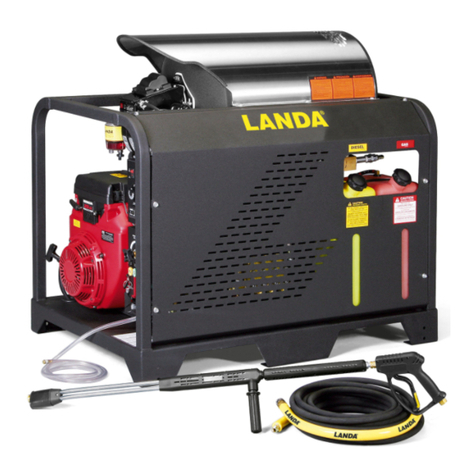
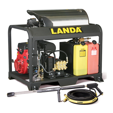
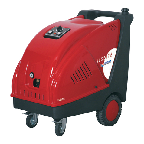
Landa vhp2-1500 User manual

8.913-949.0
OPERATOR’S MANUAL
For technical assistance or the Landa Dealer nearest you,
consult our web page at www.landa.com
■ VHP2-1500 (1.109-556.0) ■ VHP3-2000 (1.109-557.0)
WARNING
Tipover Hazzard
89139490-1
USE VAPOR FUEL ONLY
L
I
S
T
E
D
®
VHP

CONTENTS
2
Model Number ______________________________
Serial Number ______________________________
Date of Purchase ____________________________
The model and serial numbers will be found on a decal attached
to the pressure washer.You should record both serial number and
date of purchase and keep in a safe place for future reference.
LANDA VHP • 8.913-949.0 • Rev. 5/13
Introduction & Important Safety Information..................................... 3-5
Component Identification..................................................................... 6
Installation ........................................................................................ 7-8
Pre-Operation Checklist ...................................................................... 8
Instructions for Lighting ....................................................................... 9
Assembly Instructions........................................................................ 10
Operating Instructions ....................................................................... 11
Detergents and General Cleaning Techniques .................................. 12
Shutting Down and Clean up............................................................. 13
Storage .............................................................................................. 13
Troubleshooting ............................................................................ 14-15
Maintenance and Service............................................................. 16-17
Oil Change Record............................................................................ 17
Exploded View ............................................................................. 18-19
Exploded View Parts List .............................................................. 20-22
Hose & Spray Gun Assembly ............................................................ 23
Pump Exploded View and Parts List............................................. 24-25
VRT 3 Unloader Exploded Views and Parts List................................ 26
Injector Assemblies ........................................................................... 27
Warranty ............................................................................................ 28
Spanish......................................................................................... 29-37

LANDA VHP • 8.913-949.0 • Rev. 5/13
3
PRESSURE WASHER OPERATOR’S MANUAL
INTRODUCTION & IMPORTANT SAFETY INFORMATION
Thank you for purchasing this Pressure Washer.
We reserve the right to make changes at any time
without incurring any obligation.
Owner/User Responsibility:
The owner and/or user must have an understanding of
the manufacturer’s operating instructions and warnings
before using this pressure washer. Warning information
should be emphasized and understood. If the operator
is not fluent in English, the manufacturer’s instructions
and warnings shall be read to and discussed with
the operator in the operator’s native language by the
purchaser/owner, making sure that the operator com-
prehends its contents.
Owner and/or user must study and maintain for future
reference the manufacturers’ instructions.
The operator must know how to stop the machine
quickly and understand the operation of all controls.
Never permit anyone to operate the engine without
proper instructions.
SAVE THESE INSTRUCTIONS
This manual should be considered a permanent
part of the machine and should remain with it if
machine is resold.
When ordering parts, please specify model and
serial number. Use only identical replacement parts.
This machine is to be used only by trained operators.
IMPORTANT SAFETY
INFORMATION
READ OPERATOR’S
MANUAL THOROUGHLY
PRIOR TO USE.
WARNING: To reduce the risk of
injury, read operating instruc-
tions carefully before using.
1. Read the owner's manual
thoroughly. Failure to follow
instructions could cause mal-
function of the machine and
result in death, serious bodily
injury and/or property dam-
age.
2. Know how to stop the machine and bleed pressure
quickly. Be thoroughly familiar with the controls.
3. Stay alert — watch what you are doing.
4. Do not replace LP tank while machine is running.
5. All installations must comply with local codes. Con-
tact your electrician, plumber, utility company or the
selling distributor for specific details. If your machine
is rated 250 volts or less, single phase will be pro-
vided with a ground fault circuit interrupter (GFCI).
If rated more than 250 volts, or more than single
phase this product should only be connected to a
power supply receptacle protected by a GFCI.
DANGER: Improper connection of the equipment-
grounding conductor can result in a risk of elec-
trocution. Check with a qualified electrician or
service personnel if you are in doubt as to whether
the outlet is properly grounded. Do not modify the
plug provided with the product - if it will not fit the
outlet, have a proper outlet installed by a qualified
electrician. Do not use any type of adaptor with
this product.
WARNING
KEEP WATER
SPRAY AWAY FROM
ELECTRICAL WIRING.
WARNING: Keep wand, hose, and
water spray away from electric
wiring or fatal electric shock may
result.
6. To protect the operator from
electrical shock, the machine
must be electrically grounded.
It is the responsibility of the
owner to connect this machine
to a UL grounded receptacle of proper voltage and
amperage ratings. Do not spray water on or near
electrical components. Do not touch machine with
wet hands or while standing in water. Always dis-
connect power before servicing.
RISK OF EXPLOSION:
IF GAS SMELL
PRESENT TURN OFF
SUPPLY
WARNING
WARNING: Flammable liquids
can create fumes which can ig-
nite, causing property damage
or severe injury.
WARNING: Risk of explosion —
Operate only where open flame
or torch is permitted.
RISK OF FIRE.
DO NOT ADD FUEL
WHEN OPERATING
MACHINE.
WARNING
WARNING: Risk of fire — Do not
change tanks when the product
is operating or still hot.
WARNING: Use vapor fuel only.
7. Oil burning appliances shall
be installed only in locations
where combustible dusts and
flammable gases or vapors
are not present. Do not store
or use gasoline near this machine.
8. Keep operating area clear of all persons.
WARNING
USE PROTECTIVE
EYE WEAR
AND CLOTHING
WHEN OPERATING
THIS EQUIPMENT.
WARNING: High pressure spray
can cause paint chips or other
particles to become airborne
and fly at high speeds. To avoid
personal injury, eye, hand and
foot safety devices must be
worn.
9. Eye, hand, and foot protection
must be worn when using this
equipment.

LANDA VHP • 8.913-949.0 • Rev. 5/13
OPERATOR’S MANUAL
PRESSURE WASHER
4
WARNING: Protect machine from
freezing.
13. To keep machine in best
operating conditions, it is
important you protect machine
from freezing.Failure to protect
machine from freezing
could cause malfunction of the
machine and result in death,
serious bodily injury, and/or property damage. Fol-
low storage instructions specified in this manual.
14. Inlet water must be clean fresh water and no hotter
then 90°F.
WARNING
RISK OF
ASPHYXIATION. USE
THIS PRODUCT ONLY
IN A WELL
VENTILATED AREA.
WARNING: Risk of asphyxiation.
Use this product only in a well
ventilated area.
15. Avoid installing machines in
small areas or near exhaust
fans. Adequate oxygen is
needed for combustion or
dangerous carbon monoxide
will result.
16. Manufacturer will not be liable for any changes
made to our standard machines or any components
not purchased from us.
17. The best insurance against an accident is precau-
tion and knowledge of the machine.
WARNING
RISK OF INJURY
FROM FALLS WHEN
USING LADDER.
WARNING: Be extremely careful
when using a ladder, scaffolding
or any other relatively unstable
location. The cleaning area
should have adequate slopes
and drainage to reduce the pos-
sibility of a fall due to slippery
surfaces.
18. Do not overreach or stand on unstable support.
Keep good footing and balance at all times.
19. Do not operate this machine when fatigued or under
the influence of alcohol, prescription medications,
or drugs.
20. Follow the maintenance instructions specified in
the manual.
21. Do not replace LP tank while machine is running.
Serious injury could result.
WARNING: Use vapor fuel only.
22. The LP models are designed to run on vapor pro-
pane fuel. Do not use liquid fuel. Have a qualified
serviceman install and service your equipment.
IMPORTANT SAFETY INFORMATION
WARNING
EAR PROTECTION
MUST BE WORN
WARNING:This machine exceeds
85 db appropriate ear protection
must be worn.
HOT DISCHARGE FLU-
ID: DO NOT TOUCH OR
DIRECT DISCHARGE
STREAM AT PERSONS.
CAUTION: Hot discharge fluid.
Do not touch or direct discharge
stream at persons.
WARNING: This machine pro-
duces hot water and must have
insulated components attached
to protect the operator.
WARNING
Risk Of Injury.
Hot Surfaces
Can Cause Burns
WARNING: Risk of injury. Hot
surfaces can cause burns. Use
only designated gripping areas
of spray gun and wand. Do not
place hands or feet on non-insu-
lated areas of the pressure
washer.
10. To reduce the risk of injury, close supervision is
necessary when a machine is used near children.
Do not allow children to operate the pressure
washer. This machine must be attended during
operation.
TRIGGER GUN KICKS
BACK - HOLD WITH
BOTH HANDS
WARNING
WARNING: Grip cleaning wand
securely with both hands before
starting. Failure to do this could
result in injury from a whipping
wand.
11. Never make adjustments on
machine while in operation.
12. Be certain all quick coupler fit-
tings are secured before using
pressure washer.
RISK OF INJECTION
OR SEVERE INJURY
TO PERSONS. KEEP
CLEAR OF NOZZLE.
WARNING
WARNING: High pressure devel-
oped by these machines will
cause personal injury or equip-
ment damage. Keep clear of
nozzle. Use caution when oper-
ating. Do not direct discharge
stream at people, or severe in-
jury or death will result.
WARNING
PROTECT FROM
FREEZING

LANDA VHP • 8.913-949.0 • Rev. 5/13
5
PRESSURE WASHER OPERATOR’S MANUAL
23. Never expose a spark or flame where there may
be unburned gas present.
24. Install the machine 18” above the floor and about
2 feet from wall providing adequate ventilation and
space.
25. When making repairs disconnect from electrical
source and shut off gas valve.
26. Install this machine on non combustible flooring.
27. Do not allow acids, caustic or abrasive fluids to pass
through the pump.
28. Never run pump dry or leave spray gun closed
longer than 1-2 minutes.
WARNING: If connection is made to portable water
supply, a back flow device must be provided.
Follow the maintenance instructions speci-
fied in the manual.
IMPORTANT SAFETY INFORMATION
Example Of Down
Draft Diverter
For Gas Fired
Machines

LANDA VHP • 8.913-949.0 • Rev. 5/13
OPERATOR’S MANUAL
PRESSURE WASHER
6
COMPONENT IDENTIFICATION
89139490-2
LP Tank
(not
included)
High Pressure
Hose Hanger
Wand
Holder
High
Pressure
Hose
Trigger
Spray Gun
Variable Pressure
Control Handle
Variable
Pressure
Wand
Brass Soap
Nozzle
GFCI
Propane
Hose
LP Shelf
Water Supply
(not included)
Pump &
Burner Switch
Wand
Rest
Discharge
Nipple
High Limit
Snap Switch
Quick
Coupler
Rupture
Disk
Collar
Detergent
Injector
Nozzle
Quick
Coupler
Reversed View

LANDA VHP • 8.913-949.0 • Rev. 5/13
7
PRESSURE WASHER OPERATOR’S MANUAL
INSTALLATION
WARNING: Moving this machine on an incline may
cause instability and could result in the machine
tipping over. Equipment damage or bodily harm
could occur.
Place machine in a convenient location providing ample
support, drainage and room for maintenance.
These machines are intended for indoor use. Ma-
chine must be stored indoors when not in use.
Location:
The location should protect the machine from damag-
ing environmental conditions, such as wind, rain and
freezing.
1. The machine should be run on a level surface
where it is not readily influenced by outside sources
such as strong winds, freezing temperatures, rain,
etc. Consider accessibility for the replacing of LP
tanks, refilling of detergents, adjustments and
maintenance when selecting a location. Normal
precautions should be taken by the operator to
prevent excess moisture from reaching electrical
components.
2. It is recommended that a partition be made be-
tween the wash area and the machine to prevent
direct spray from the spray gun to come in contact
with machine. Excess moisture reaching the elec-
trical controls will reduce the machine life and may
cause electrical shorts.
3. During installation, beware of poorly ventilated
locations or areas where exhaust fans may cause
an insufficient supply of oxygen. Sufficient combus-
tion can only be obtained when there is a sufficient
supply of oxygen available for the amount of fuel
being burned. If it is necessary to install in a poorly
ventilated area, outside fresh air may have to be
piped to the burner and a fan installed to bring air
into the room. Avoid small locations or areas near
exhaust fans.
Gas Codes:
Confer with local gas company and with proper mu-
nicipal officials regarding any specific code or regula-
tions governing the installation. The installation must
conform to local codes.
The gas pressure coming out of the regulator and going
to the burner ring has been factory set for elevations of
0 to 2000 ft. Altitudes greater than 2000 ft will require
adjustments to the gas manifold pressures. Consult
your local service dealer/distributor for high altitude
adjustments. In Canada, certification for installation
at altitudes over 4500 feet above sea level is the juris-
diction of local authorities.You should not readjust the
burner ring gas pressure. If you replace your gas valve,
you will need to adjust the new valve. Refer to your
machine’s specification plate for the correct pressure
setting. Follow the installation and adjustment instruc-
tions provided with your replacement valve.
NOTE:Air for combustion and ventilation along with
exhaust flue sizing must conform to methods outlined
in current American Standard (ANSI-Z223.1) National
Fuel Gas Code or National Standard of Canada CSA-
149.1 and CSA-149.2 “Installation Code for Gas Burn-
ing Appliances”.
Electrical:
This machine, when installed, must be electrically
grounded in accordance to local codes. Check for
proper power supply using a volt meter. The VHP2-
15021D requires a 20 amp receptacle to comply with
UL 1776 certification standards.
Venting:
Regulations or ventilation concerns may call for a
chimney or furnace pipe.
When venting, if the machine is to be in an enclosed
area with a chimney on it, be sure the chimney is the
same size as the stack on the machine. Poor draft
will cause machine to soot and not operate efficiently.
When placing for installation, keep in mind that the
pressure washer should be positioned in such a man-
ner that the stack will be as straight as possible and
protrude through the roof of the building at a proper
location and at sufficient height to eliminate downdraft.
The chimney of gas fired machines should be installed
with a down draft diverter.
Draft Diverter:
A draft diverter should be installed above the heating
coil. The diverter serves to sever the chimney effect
created in all sections of furnace pipe positioned below
to enhance the draft through the burner. It also helps
prevent freezing of the coil due to wind chill factors.
NOTE: the draft diverter is not standard on VHP ma-
chines.
When the pressure washer is installed in a tightly closed
room without ventilation openings to the outdoors or
other rooms, provisions shall be made for supplying
air for combustion through special openings, one near
the floor line and the other near the ceiling, each to be
sized on the basis of one square inch or more of free
area for each 1,000 BTU input per hour.

LANDA VHP • 8.913-949.0 • Rev. 5/13
OPERATOR’S MANUAL
PRESSURE WASHER
8
Placement:
Do not locate near any combustible material. Keep all
flammable material at least 20 feet away.
Allow enough space for servicing the machine.
Local code will require certain distances from floor and
walls. (Two feet away should be adequate.)
Water Source:
Water source for machine should be supplied by a 5/8"
I.D. garden hose with a city water pressure of not less
than 30 psi. If the water supply is inadequate, or if the
garden hose is kinked, the machine will run very rough
and the burner will not fire.
Connection:
Connect the wand, nozzle, hose and spray gun (where
applicable). On pipe thread connections, use teflon
tape to avoid water leaks. (See Component Identifica-
tion.)
Attach high pressure hose to discharge nipple by pull-
ing the quick coupler collar back and inserting it onto
the discharge nipple. Then push the collar forward to
secure. A detergent injector could be inserted between
the hose coupler and the discharge nipple. (See page
10.)
Place detergent dip tube into liquid soap or detergent
solution. Avoid letting tube suck air.
CAUTION:When installing propane hose to LP tank,
please note that it has left hand threads.
Inspection and Testing:
Before turning gas under pressure into piping, all open-
ings from which gas can escape should be closed.
Immediately after turning on gas, the system should
be checked for leaks.This can be done by watching the
1/2 cubic foot test dial and allowing 5 minutes to show
any movement, or by soaping each pipe connection
and watching for bubbles. If a leak is found, make the
necessary repairs and repeat the above test.
Defective pipes or fittings should be replaced and not
repaired. Never use a flame or fire in any form to locate
gas leaks, use a soap solution.
After the piping and meter have been checked com-
pletely, purge the system of air. DO NOT bleed the air
inside an enclosed room.
The pressure washer and its individual shut-off valve
must be disconnected from the gas supply piping
system during the pressure testing of that system at
test pressure in excess of 1/2 psig or damage to the
gas valve will occur.
Shut-Off Valve:
A gas shut-off valve has been installed between the gas
supply line and the washer.The plumbing also includes
a union between the shut-off valve and the burner.
Condensation from Coils:
When cold water is being pumped into the water heater
coils, and the burners are on, condensation will form on
the coils and drip down into the burner compartment
giving the appearance of a leaking coil, particularly on
cold humid days.
Check Water Heater Coil for Leaks:
With the burner “OFF” start the pumping machine and
allow to run for a few minutes. Look into the burner
compartment with a drop light or flashlight. If no leak
is visible, then subsequent water dripping from the coil
will be from condensation in the flue gases when the
burner is on, as described in the previous paragraph.
INSTALLATION
PRE-START CHECK LIST YES NO
Is machine protected from down-
draft and excessive wind?
Is machine shielded from moisture
or water spray?
Is the voltage correct and circuit
breaker and supply cord adequate
according to specifications and
serial plate notation?
Is the machine electrically
grounded?
Is there ample water supply?
Have all flammable liquids or gases
been removed from installation
location?
Is the machine properly vented to
allow adequate air flow?
Is there an adequate gas supply for
the BTU rating of the burner?
Have gas lines been checked for
gas leaks?
Have all operators using this
machine been instructed properly
& have they read the manual?
Has the machine been installed
according to the instructions in the
operator's manual?
Is the incoming gas supply pressure
to the machine between 6-14 water
column inches or 1/2 psig?

LANDA VHP • 8.913-949.0 • Rev. 5/13
9
PRESSURE WASHER OPERATOR’S MANUAL
WARNING: If“NO” has been checked on any of the
above questions, do not operate.
WARNING: If you do not follow
instructions exactly, a fire or
explosion may result causing
property damage, personal in-
jury or loss of life.
1. This machine has a pilot
which must be lighted by
hand. When lighting the pi-
lot, follow these instructions
exactly.
2. BEFORE LIGHTING smell all around the appli-
ance area for gas. Be sure to smell next to the floor
because propane gas is heavier than air and will
settle on the floor.
For your safety:
“WHAT TO DO IF YOU SMELL GAS”
a. Do not try to light any appliance.
b. Do not touch any electrical switch; do not
use any phone in your building.
c. Immediately call your gas supplier from a
neighbor’s phone. Follow the gas supplier’s
instructions.
d. If you cannot reach your gas supplier, call
the fire department.
3. Use only your hand to push in or turn gas control
knob. Never use tools. If the knob will not push in
or turn by hand, don’t try to repair it, call a qualified
service technician. Force or attempted repair may
result in a fire or explosion.
4. Do not use this machine if any part has been
under water. Immediately call a qualified service
technician to inspect the machine and to replace
any part of the control system or any gas control
that has been under water.
WARNING
RISK OF FIRE OR
EXPLOSION:
FOLLOW
INSTRUCTIONS
EXACTLY.
INSTRUCTIONS FOR LIGHTING

LANDA VHP • 8.913-949.0 • Rev. 5/13
OPERATOR’S MANUAL
PRESSURE WASHER
10
ASSEMBLY INSTRUCTIONS
STEP 1: Connect power cord to
proper electrical outlet according
to serial plate information. Push
in GFCI reset button. The VHP2-
15021D requires a 20 amp recep-
tacle.
STEP 2: Connect high pressure
hose to discharge nipple by slid-
ing quick coupler collar back. (If
detergent is to be applied, insert
a detergent injector.) Insert quick
coupler onto discharge nipple and
secure by pushing quick coupler
collar forward.
STEP 3: Attach the high pressure
hose to the spray gun using teflon
tape on hose threads. Move safety
latch into locked position.
STEP 4: Check oil level by using
supplied dip-stick. Use SAE 30W
non-detergent only.
Detergent
Injector
Safety
Latch
High
Pressure
Hose
Spray
Gun
High
Pressure
Hose
Discharge
Nipple
Detergent
Suction
Tube
STEP 5: Connect propane hose to
a propane tank.
Propane
Hose
STEP 1: STOP! Read operator’s manual
before operating this machine. Failure to
read operation and warning instructions may
result in personal injury or property damage.
Connect water supply hose to inlet connec-
tor and turn water on.
STEP 2: Turn all switches off. Remove and
position LP tank as far from machine as supply
hose will allow.
89139490-5
Turn Pump/
Burner
Switch Off
OPERATING INSTRUCTIONS

LANDA VHP • 8.913-949.0 • Rev. 5/13
11
PRESSURE WASHER OPERATOR’S MANUAL
Variable Pressure
Control Handle
Trigger
Variable Pressure
Wand (VP)
High
Pressure
Nozzle
Brass Soap
Nozzle
STEP 6: Selection of high or low pressure is ac-
companied by turning the handle. Note: High
pressure nozzle must be inserted at end of wand to
obtain high pressure.To apply soap read operator's
manual.
STEP 5: Release the coupler
collar and push the nozzle until
the collar clicks. Pull the nozzle to
make sure it is seated properly.
STEP 4: Pull the spring-loaded
collar of the wand coupler col-
lar back to insert your choice
of pressure nozzle. CAUTION:
Never replace nozzles without
engaging the safety latch on
the spray gun trigger.
Coupler
Collar
OPERATING INSTRUCTIONS
STEP 3: Before installing nozzle, Pull
trigger on spray gun allowing water to flow
until all air has been discharged from the
system. Check for water leaks and tighten
as needed.
Grip spray gun variable pressure wand
securely. Then turn the variable pressure
control handle counterclockwise to flush
any debris out of soap nozzle.
89139490-6
Pump and Burner
Switch
STEP 9: Turn switch to pump position and
pull the trigger on the spray gun. Turn vari-
able pressure control wand handle clockwise
to obtain pressure for cold water operation.
For hot water, turn the switch to the burner
position and pull the trigger on the spray gun.
To apply detergent, read section on Deter-
gents and General Cleaning Techniques.
STEP 7: Open valve on LP tank, then slightly depress
main gas valve control knob on the right side of the ma-
chine and turn it counterclockwise to the Pilot position.
NOTE: Knob cannot be turned from “Pilot” to “OFF” unless
the knob is slightly depressed.
Step 8: Depress the control knob all the way and hold it in. After
five (5) seconds, depress the red ignitor until you hear a loud click.
Repeat 3 or 4 times if necessary until pilot is lit. If pilot does not
remain lit, repeat operation allowing a longer period of time before
releasing the gas valve knob. After the pilot lights, continue to hold
the control knob down for about one (1) minute before releasing.
Look at the pilot viewing mirror at the rear of the machine.
Turn gas control knob counterclockwise to “ON.”
Control
Knob
Gas
Valve
Red
Ignitor

LANDA VHP • 8.913-949.0 • Rev. 5/13
OPERATOR’S MANUAL
PRESSURE WASHER
12
WARNING: Some detergents
may be harmful if inhaled or
ingested, causing severe nau-
sea, fainting or poisoning. The
harmful elements may cause
property damage or severe
injury.
STEP 1: Use detergent designed
specifically for pressure washers.
Household detergents could dam-
age the pump. Prepare detergent
solution as required by the manu-
facturer. Fill a container with pres-
sure washer detergent. Place the
filter end of detergent suction tube
into the detergent container.
STEP 2: Apply safety latch to spray gun trigger.
Secure black detergent nozzle into quick coupler.
NOTE: Detergent cannot be applied using the yellow
nozzle.
STEP 3: With the motor
running, pull trigger to oper-
ate machine. Liquid deter-
gent is drawn into the ma-
chine and mixed with water
at an approximate ratio of 15
to 1. Turn pressure control
handle on wand counterclock-
wise. This lowers the pressure by directing the water
flow through the soap nozzle and allow detergent
injector to siphon soap.
Apply detergent to work area. Do not allow detergent
to dry on surface.
IMPORTANT:You must flush the detergent injection
system after each use by placing the suction tube
into a bucket of clean water, then run the pressure
washer in low pressure for 1-2 minutes.
CLEANING TIPS
Pre-rinse cleaning surface with fresh water. Place de-
tergent suction tube directly into cleaning solution and
apply to surface at low pressure (for best results, limit
your work area to sections approximately 6 feet square
and always apply detergent from bottom to top). Allow
detergent to remain on surface 1-3 minutes. Do not
allow detergent to dry on surface. If surface appears
to be drying, simply wet down surface with fresh water.
If needed, use brush to remove stubborn dirt. Rinse at
high pressure from top to bottom in an even sweeping
motion keeping the spray nozzle approximately 1 foot
from cleaning surface. Use overlapping strokes as you
clean and rinse any surface. For best surface cleaning
action, spray at a slight angle.
Recommendations:
• Before cleaning any surface, an inconspicuous
area should be cleaned to test spray pattern and
distance for maximum cleaning results.
• If painted surfaces are peeling or chipping,
use extreme caution as pressure washer may
remove the loose paint from the surface.
• Keepthespraynozzleasafedistancefromthe
surface you plan to clean. High pressure wash
a small area, then check the surface for dam-
age. If no damage is found, continue to pressure
washing.
CAUTION - Never use:
• Bleach, chlorine products and other corrosive
chemicals
• Liquidscontainingsolvents(i.e.,paintthinner,
gasoline, oils)
• Tri-sodiumphosphateproducts
• Ammoniaproducts
• Acid-basedproducts
These chemicals will harm the machine and will dam-
age the surface being cleaned.
RINSING
It will take a few seconds for the detergent to clear.
Apply safety latch to spray gun. Remove black soap
nozzle from the quick coupler. Select and install the
desired high pressure nozzle. NOTE: You can also stop
detergent from flowing by simply removing detergent
siphon tube from bottle.
WARNING
DETERGENTS & GENERAL CLEANING TECHNIQUES

LANDA VHP • 8.913-949.0 • Rev. 5/13
13
PRESSURE WASHER OPERATOR’S MANUAL
89139490-7
SHUTTING DOWN AND CLEAN-UP
CAUTION: Always store your pressure washer in a
location where the temperature will not fall below
32°F (0°C).The pump in this machine is susceptible
to permanent damage if frozen. FREEZE DAMAGE
IS NOT COVERED BY WARRANTY.
1. Stop the pressure washer, squeeze spray gun trig-
ger to release pressure.
2.
Detach water supply hose and high pressure hose.
3. Turn on the machine for a few seconds, until re-
maining water exits. Turn engine off immediately.
4. Drain the gas and oil from the engine.
5.
Do not allow high pressure hose to become kinked.
6. Store the machine and accessories in a room which
does not reach freezing temperatures.
CAUTION: Failure to follow the above directions will
result in damage to your pressure washer.
When the pressure washer is not being operated or is
being stored for more than one month, follow these
instructions:
1. Replenish engine oil to upper level.
2. Drain gasoline from fuel tank, fuel line, fuel valve
and carburetor.
3. Pour about one teaspoon of engine oil through
the spark plug hole, pull the starter grip several
times and replace the plug. Then pull the starter
grip slowly until you feel increased pressure which
indicates the piston is on its compression stroke and
leave it in that position. This closes both the intake
and exhaust valves to prevent rusting of cylinder.
4. Cover the pressure washer and store in a clean, dry
place that is well ventilated away from open flame
or sparks. NOTE: The use of a fuel additive, such
as STA-BIL®, or an equivalent, will minimize the
formulation of fuel deposits during shortage. Such
additives may be added to the gasoline in the fuel
tank of the engine, or to the gasoline in a storage
container.
After Extended Storage
CAUTION: Prior to restarting, thaw out any
possible ice from pressure washer hoses,
spray gun or wand.
Engine Maintenance
During the winter months, rare atmospheric conditions
may develop which will cause an icing condition in the
carburetor. If this develops, the engine may run rough,
lose power and may stall. This temporary condition can
be overcome by deflecting some of the hot air from the
engine over the carburetor area. NOTE: Refer to the
engine manufacturer's manual for service and mainte-
nance of the engine.
STORAGE
STEP 2: After water has cooled,
turn pump off. Turn main gas valve
off, then close the valve on the LP
tank. Secure the LP tank to the
machine when moving it.
STEP 3: Turn the water off. To pro-
tect from freezing, pull the trigger
on spray gun to allow water to drain
from the system.
STEP 1: Remove detergent suction
tube from container and insert into
one (1) gallon of fresh water. Flush
detergent lines with fresh water,
switch to the pump position and
continue to spray water allowing
burner to cool.
STEP 4: Squeeze trigger on spray
gun to relieve remaining pressure.
Move safety latch into its locked
position.
Pump Switch

LANDA VHP • 8.913-949.0 • Rev. 5/13
PRESSURE WASHER Troubleshooting Guide
14
TROUBLESHOOTING
PROBLEM POSSIBLE CAUSE SOLUTION
PULSATION Faulty pulsation damper Check precharge. If low, recharge or install
new one.
LOW
PRESSURE
Worn nozzle Replace with nozzle of proper size.
Belt slippage Tighten or replace with correct belt.
Air leak in inlet plumbing Disassemble, reseal and reassemble.
Relief valve stuck, partially plugged or
improperly adjusted. Valve seat worn
Clean and adjust relief valve; check for
worn or dirty valve seats. Kit available.
Inlet suction strainer clogged or
improperly sized
Clean. Use adequate size. Check more
frequently.
Worn packing.
Abrasives in pumped in cavitation.
Inadequate water
Install proper filter. Suction at inlet mani-
fold must be limited to lifting less than 20
feet of water or 8.5 psi vacuum.
Fouled or dirty inlet or discharge valves Clean inlet and discharge valve
assemblies.
Worn inlet, discharge valve blocked
or dirty
Replace worn valves, valve seats and/or
discharge hose.
Leaky discharge hose Replace.
PUMP RUNS
EXTREMELY ROUGH,
PRESSURE
VERY LOW
Restricted inlet or air entering the inlet
plumbing
Proper size inlet plumbing; check for air
tight seal.
Inlet restrictions and/or air leaks. Stuck
inlet or discharge valve
Replace worn cup or cups. Clean out
foreign material. Replace worn valves.
WATER LEAKAGE
FROM UNDER
MANIFOLD.
Worn packing Install new packing.
OIL LEAKING IN AREA
OF CRANKSHAFT
Worn crankshaft seal or improperly
installed oil seal O-ring
Remove oil seal retainer and replace
damaged O-ring and/or seals.
Bad bearing Replace bearing.
EXCESSIVE
PLAY IN END OF
CRANKSHAFT
PULLEY
Worn main bearing from excessive
tension on drive belt
Replace crankcase bearing and/or
tension drive belt.
WATER IN
CRANKCASE
Humid air condensing into water inside
crankcase
Change oil intervals. Use any high grade
automotive 30 weight non-detergent oil.
Worn packing and/or piston rod sleeve;
O-rings on plunger retainer worn
Replace packing. Replace O-rings.
OIL LEAKING FROM
UNDERSIDE OF
CRANKCASE
Worn crankcase piston rod seals Replace seals.
OIL LEAKING AT
REAR PORTION
OF CRANKCASE
Worn crankcase piston rod seals Replace seals.
LOUD KNOCKING Pulley loose on crankshaft Check key and tighten set screw.
NOISE IN PUMP Broken or worn bearing Replace bearing.

LANDA VHP • 8.913-949.0 • Rev. 5/13
15
PRESSURE WASHER Troubleshooting Guide
TROUBLESHOOTING
PROBLEM POSSIBLE CAUSE SOLUTION
PUMP
NOISY
Air in suction line Check water supply and connections on
suction line.
Broken or weak inlet or discharge
valve springs
Check and replace if necessary.
Excessive matter in valves Check and clean if necessary.
Worn bearings Check and replace if necessary.
PRESENCE OF
WATER IN OIL
Oil seal worn Check and replace if necessary.
High humidity in air Check and change oil twice as often.
WATER DRIPPING
FROM UNDER PUMP
Piston packing worn Check and replace if necessary.
O-ring plunger retainer worn Check and replace if necessary.
Pump protector Check inlet water pressure.
OIL DRIPPING Oil seal worn Check and replace if necessary.
EXCESSIVE
VIBRATION IN
DELIVERY LINE
Irregular functioning of the valves Check and replace if necessary.
RELIEF VALVE
LEAKS WATER
Wrong nozzle size, debris in nozzle Clean or replace with correct nozzle.
BURNER WILL
NOT LIGHT
No fuel Open gas valve.
Pilot light is out Light pilot.
Defective high limit switch Replace switch.
BURNER SMOKES Stack restriction See venting under installation (page 7).
PILOT DOES
NOT LIGHT
Manual pilot valve closed Open pilot valve.
Gas leak in pilot Call qualified serviceman.
Piezo ignitor Adjust spark gap. Secure wires.
PILOT IGNITES BUT
WILL NOT STAY ON
WHEN GAS COCK
DIAL IS RELEASED
Pilot too far away from thermocouple Adjust thermocouple closer to flame.
Thermocouple loose at regulator
safety valve
Tighten to firm fit.
SHORT
THERMOCOUPLE
LIFE
Excessive heat from pilot light Decrease pilot supply gas.
Thermocouple too close to pilot Adjust thermocouple farther away.
BURNER CYCLING
ON/OFF
Defective high limit switch Replace switch.
WASHER WILL
NOT STEAM
Steam valve closed Open valve (counterclockwise).
Burner not on Turn burner switch to "ON" position.
Coil dirty or sooty See coil maintenance section.
Steam valve clogged Clean or replace.

LANDA VHP • 8.913-949.0 • Rev. 5/13
OPERATOR’S MANUAL
PRESSURE WASHER
16
MAINTENANCE & SERVICE
PREVENTATIVE
MAINTENANCE
1. Check to see that the water pump is properly
lubricated.
2. Follow winterizing instructions to prevent freeze
damage to the pump and coils.
3. Always neutralize and flush detergent from system
after use.
4. If water is known to be high in mineral content, use
a water softener in your water system or de-scale
as needed.
5. Do not allow acidic, caustic or abrasive fluids to be
pumped through system.
6. Always use high grade quality Landa cleaning
products.
7. Never run pump dry for extended periods
of time.
8. Periodically delime coils as per instructions.
It is advisable, periodically, to visually inspect the
burner. Check air inlet to make sure it is not clogged
or blocked. Wipe off any oil spills and keep this equip-
ment clean and dry.
The areas around the Landa washer should be kept
clean and free of combustible materials, gasoline and
other flammable vapors and liquids.
The flow of combustion and ventilating air to the burner
must not be blocked or obstructed in any manner.
MAINTENANCE AND SERVICE
Unloader Valves:
Unloader valves relieve pressure in the line when
the shut-off spray gun is closed. Unloader valves are
preset and tested at the factory before shipping. Oc-
casional adjustment of the unloader may be neces-
sary to maintain correct pressure. (Contact your local
dealer for correct procedure in adjusting unloader
valve.) Tampering with the factory setting may cause
personal injury and/or property damage, and will void
the manufacturer's warranty.
Winterizing Procedure:
Damage due to freezing is not covered by warranty.
Adhere to the following cold weather procedures when-
ever the washer must be stored or operated outdoors
under freezing conditions.
During winter months, when temperatures drop below
32°F, protecting your machine against freezing is nec-
essary. Store the machine in a heated room. If this is not
possible then mix a 50/50 solution of anti-freeze/water
into a 5 gallon bucket and with a short section of garden
hose elevate the bucket and turn the pump on to siphon
the anti-freeze through the machine. If compressed air
is available, an air fitting can be screwed into the inlet
connector and, by injecting compressed air, all water
will be blown out of the system.
High Limit Hot Water Thermostat:
For safety, each machine is equipped with a high limit
control switch. In the event the temperature of the water
should exceed its operating temperature, the high limit
control will turn the burner off until the water cools.
Pumps:
Use only SAE 30 weight non-detergent oil. Change oil
after first 50 hours of use.Thereafter, change oil every
three months or at 500 hour intervals. Oil level should
be checked through use of the dipstick found on the
top of the pump or by the red dot visible through the oil
gauge window. Oil should be maintained at that level.
Cleaning of Coils:
In alkaline water areas, lime deposits can accumulate
rapidly inside the coil pipes.This growth is increased by
the extreme heat build up in the coil. The best preven-
tion for liming conditions is to use high quality cleaning
detergents. In areas where alkaline water is an extreme
problem, periodic use of Landa Deliming Powder (part
#9-028008) will remove lime and other deposits before
coil becomes plugged. (See Deliming Instructions for
use of Landa Deliming Powder.)
Deliming Coils:
Periodic flushing of coils is recommended.
1. Fill a container with 4 gallons of water, then add 1
lb. of deliming powder. Mix thoroughly.
2. Remove wand assembly from spray gun and put
spray gun into container. Secure the trigger on the
spray gun into the open position.
3. Attach a short section (3-5 ft.) of garden hose to
machine to siphon solution from an elevated con-
tainer.Turn pump switch on allowing solution to be
pumped through coils back into the container. Solu-
tion should be allowed to circulate 2-4 hours.
4. After circulating solution, flush entire system with
fresh water. Reinstall wand assembly to spray
gun.
Removal of Soot and Heating Coil:
In the heating process, fuel residue in the form of soot
deposits may develop between the heating coil pipe
and block air flow which will affect burner combustion.
When soot has been detected on visual observation,
the soot on the coil must be washed off after following
the coil removal steps.

LANDA VHP • 8.913-949.0 • Rev. 5/13
17
PRESSURE WASHER OPERATOR’S MANUAL
MAINTENANCE & SERVICE
1. Remove the tank head assembly by unscrewing
the three Tek screws and lifting the tank head off.
2. Remove the two pipe nipples and associated fit-
tings.
3. Lift the coil out of the outer wrap.
CAUTION:The coil weighs about 80 lbs. Use proper
lifting techniques.
4. Clean, repair and replace the coil by reversing the
above steps.
Pressure Relief Valve:
Each machine is equipped with a relief valve to relieve
pressure in the system when higher than normal oper-
ating pressures are encountered. Unusually high pres-
sures come from an object plugging the spray nozzle.
This problem can easily be remedied by removing the
obstruction. If operating pressure of machine is found
to be normal and relief valve continues to leak, repair
or replace the valve.
Rupture Disk
If pressure from pump or thermal expansion should
exceed safe limits, the rupture disk will burst, allowing
high pressure to be discharged through hose to ground.
When disk ruptures, it needs to be replaced.
DATE OIL CHANGED
MONTH/DAY/YEAR
NO. OF OPERATING
HOURS SINCE
LAST OIL CHANGE
Propane Cylinder Capacity:
An important consideration with propane systems is the
capacity of the supply cylinder relative to the needs of
the burner. The burner operates on propane as a gas;
as gas is used from the propane cylinder, the liquid in
the cylinder boils to maintain gas pressure.This boiling
process cools the liquid, and in a heavy, continuous-
demand situation, the liquid temperature can fall to
the point at which it cannot provide gas as rapidly as
is needed. In this case, it may be necessary to warm
the propane cylinder by directing a warm spray, not
over 120° F, on the cold cylinder or by manifolding two
propane bottles together to increase total vaporization
capacity. It is recommended that a minimum 30 lb.
vapor propane bottle be used on the machine.
OIL CHANGE RECORD
DATE OIL CHANGED
MONTH/DAY/YEAR
NO. OF OPERATING
HOURS SINCE
LAST OIL CHANGE

LANDA VHP • 8.913-949.0 • Rev. 5/13
OPERATOR’S MANUAL
PRESSURE WASHER
18
Thismachine is designed to run on propane vapor fuel.
Shelfis for transporting only.
Removevapor propane tankfrom shelf beforeoperating.
Donot connect to a propane bottle.
Readoperator's manual before starting.
Thismachine is designed to run on propane vapor fuel.
Shelfis for transporting only.
Removevapor propane tankfrom shelf beforeoperating.
Donot connect to a propane bottle.
Readoperator's manual before starting.
Thismachine is designed to run on propane vapor fuel.
Shelfis for transporting only.
Removevapor propane tankfrom shelf beforeoperating.
Donot connect to a propane bottle.
Readoperator's manual before starting.
OPERATING INSTRUCTIONS INSTRUCCIONES DE OPERACION INSTRUCTIONS D' OPERATION
89139490-4
EXPLODED VIEW — LEFT SIDE
53
54
46
47
55
36
3
2
37
15
15
129
21
125
45
43
42
31
28
38
1
Tank
(Not Included,
Optional)
44
14
13
27
35
34
30
25
29
18
16
109
110
114
115
116
52
7
39
8
137 9
12
10
4
6
140
32
24
41
50
48
43
112
108
84
20
49
51
26
13
131
16111
40
133
33
19
View A-A
29
11
23
5
Electronic Ignition
(Optional)
17
127

LANDA VHP • 8.913-949.0 • Rev. 5/13
19
PRESSURE WASHER OPERATOR’S MANUAL
NeverUse:
·
Bleach,chlorineproducts and other corrosive chemicals
·
Liquidscontainingsolvents (i.e.paint thinner, gasoline, oil)
·
Tri-sodiumphosphate products
·
Ammonia products
·
Acid-based products
Thesechemicalswill harm the unit and will damage the
surfacebeingcleaned.
Usemanufacturer’sdetergentsas recommended in manual.
CAUTION
89139490-3
EXPLODED VIEW — RIGHT SIDE
56
57
59
58
62
59
63
61 60
65
71
66
70
68
67
64
73
11
81
80
79
78
77
74
99
95
102
126
92
91
120
100
120
92
132
120
75
120
96
92
97
98
97
102 101 103
104
105 94
95
106
107
91
118
83
82
117
95
94
85
119
72
86 89
87
88
90
For
Detail See
View A-A
121
22
68
128
93
69
123
120
121
43
130
119
125
11
112
122
112
122
134
135
136
138
76
139
124
133

LANDA VHP • 8.913-949.0 • Rev. 5/13
OPERATOR’S MANUAL
PRESSURE WASHER
20
EXPLODED VIEW PARTS LIST
ITEM PART NO. DESCRIPTION QTY
1 8.912-918.0 Cover, Electrical Box 1
2 9.800-016.0 Label, Disconnect PWR Supply 1
3 9.802-764.0 Screw, 10/32" x 3/4", Hex 2
4 9.802-551.0 Transformer 240/480V - 120V
(3-2000) 1
5 8.716-173.0 Fuse, Paper 1 Amp 250V
Midget (3-2000) 1
6 8.933-007.0 Fuse, 1 Amp 600V Midget
(3-2000) 2
7 9.802-793.0 Nut, Cage, 1/4" x 16 GA. 7
8 8.912-917.0 Box, Electrical, VHW, Belt 1
9.802-762.0 ▲ Screw, 10/32" x 1-1/4" 1
9.802-695.0 ▲ Nut, 10/32" Keps 6
(Electric Ignition) 10
9.800-040.0 ▲Label, Ground 1
9 8.912-919.0 Cover, Pump & Motor,
VHW Belt 1
10 8.912-888.0 Holder, Wand Bracket,
VHW/VHP 1
11 9.802-754.0 Screw, 1/4" x 1/2", HH NC,
Whiz Loc 16
12 9.800-033.0 Label, Warning Hot Water 1
13 9.802-449.0 Switch, 3 PS, 115V-230V, 1 PH 1
14 8.912-916.0 Panel, Control, VHW, Belt 1
15 9.802-759.0 Screw, 10/32" x 1/2"
BHSOC BLK 8
(Electric Ignition) 12
16 9.802-776.0 Nut, 5/16", ESNA, NC 5
17 9.802-553.0 Transformer, 120/240 -24V
.050 KVA
(Electronic Ignition Option) 1
18 9.802-514.0 Strain Relief, 1/2" LQ Tite 4
19 9.802-525.0 Locknut, 1/2" 4
20 9.802-433.0 Plug, GFCI, 240V, 20 Amp
(3-2000) 1
9.802-431.0 Cord w/GFCI, 120V 20 Amps
(2-1500) 1
21 8.932-969.0 Label, Warning, Service Cord 1
22 9.802-772.0 Screw, 10/32" x 1/4" 2
23 9.802-771.0 Screw, 10/32" x 3/4" 4
24 9.802-146.0 Swivel, 1/2" MP x 3/4" GHF
w/Strainer 1
25 8.933-006.0 Switch Flow MV 60, Yellow 1
26 8.918-210.0 Hose, 3/8" x 16", 2 Wire,
Pressure Loop 1
27 8.750-299.0 Unloader, VRT 3, 8 GPM
@4500 PSI 1
28 8.706-168.0 Elbow, 3/8" Male Pipe 1
ITEM PART NO. DESCRIPTION QTY
29 9.802-695.0 Nut, 10/32” Keps 8
30 9.802-127.0 Nipple, 1/2" JIC x 3/8" Pipe 1
31 9.802-036.0 Nipple, 1/2" JIC x 3/8" Pipe 1
32 9.802-767.0 Screw, 3/8" x 3/4" Whiz Loc 4
33 8.900-822.0 Label, VHP Operating Instr. 1
34 8.706-984.0 Adapter, 1/2" x 1/2" Pipe 1
35 8.706-844.0 Tee 1/2" Female, Pipe 1
36 8.706-797.0 Nipple, 1/2" Hex 1
37 9.802-128.0 Nipple, 1/2" JIC x 1/2" Pipe 1
38 8.707-254.0 Pump Protector, 3/8" PTP 1
39 9.802-151.0 Swivel, 1/2" JIC Fem,
Push-On 2
40 4-02110000 Hose, 1/2" Push-On 12"
41 9.802-339.0 Motor, 2 HP, 1 PH 3450 RPM,
C-Face (2-1500) 1
9.802-341.0 Motor, 5 HP 1 PH 3450 RPM
C-Face (3-2000) 1
9.800-032.0 ▲ Label, Motor Overload Reset,
Lexan 1
42 8.912-873.0 Support, Propane Tank, VHP 1
43 9.802-792.0 Nut, Cage, 3/8" x 12 Ga. 16
44 8.912-864.0 Brace, LP Bottle, VHP 1
45 8.912-879.0 Bracket, Propane Tank, VHP 1
46 8.912-882.0 Strap, Propane Tank, R/H VHP 1
47 8.912-885.0 Strap, Propane Tank, L/H VHP 1
48 8.719-063.0 Knob, 3/8" - 16 x 1-1/2" VHP 1
49 9.804-029.0 Pulley, AK64H, (2-15024D) 1
9.802-380.0 Pulley, BK80H (3-20024A) 1
50 8.715-517.0 Pulley, Bore, AK21 x 5/8"
(2-15024D) 1
9.802-377.0 Pulley, BK32 (3-20024A) 1
9.803-897.0 ▲Bushing, H x 3/4 (3-20024A) 1
51 9.802-402.0 Bushing, HX24mm 1
52 9.804-026.0 Belt, AX31 (2-15024D) 1
9.802-413.0 Belt, BX32 (3-20024A) 1
This manual suits for next models
1
Table of contents
Other Landa Pressure Washer manuals

Landa
Landa PGHW4-3000 User manual

Landa
Landa PGA3-27324 User manual

Landa
Landa PGHW4-3000 User manual

Landa
Landa VNG4-2000 User manual

Landa
Landa MPG5-5000 User manual

Landa
Landa SDHW Series User manual

Landa
Landa SGP-302214S User manual

Landa
Landa PHW User manual

Landa
Landa PDHW5-35624E User manual

Landa
Landa TR-6000 User manual

Landa
Landa Pgdc5-3500 User manual

Landa
Landa SEA3-1100 User manual

Landa
Landa MVC4-3000 User manual

Landa
Landa PG4-15321 User manual

Landa
Landa PGHW5-5000 User manual

Landa
Landa ZG3-2300 User manual

Landa
Landa XPERT-HD 3.8/35 P User manual

Landa
Landa PDE2-1100 User manual

Landa
Landa SLT6-32624E User manual

Landa
Landa WATER JET SYSTEM User manual