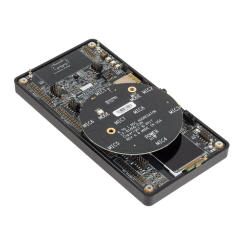
DisplayPort VIP Input Board
Evaluation Board User Guide
© 2018 Lattice Semiconductor Corp. All Lattice trademarks, registered trademarks, patents, and disclaimers are as listed at www.latticesemi.com/legal.
All other brand or product names are trademarks or registered trademarks of their respective holders. The specifications and information herein are subject to change without notice.
2 FPGA-EB-02014-1.0
Contents
Acronyms in This Document .................................................................................................................................................3
1. Introduction ..................................................................................................................................................................4
1.1. Further Information................................................................................................................................................5
2. Functional Description ..................................................................................................................................................6
2.1. Switches..................................................................................................................................................................6
2.2. DisplayPort Interface ..............................................................................................................................................6
2.3. LVDS Translator ......................................................................................................................................................6
2.4. Clock Interface........................................................................................................................................................6
3. High-Speed Headers .....................................................................................................................................................7
4. Power Supply ................................................................................................................................................................9
5. User LEDs and Headers ...............................................................................................................................................10
6. Ordering Information..................................................................................................................................................11
References ..........................................................................................................................................................................12
Technical Support Assistance .............................................................................................................................................12
Appendix A. DisplayPort VIP Input Board Schematics ........................................................................................................13
Appendix B. DisplayPort VIP Input Board Bill of Materials .................................................................................................17
Revision History...................................................................................................................................................................20
Figures
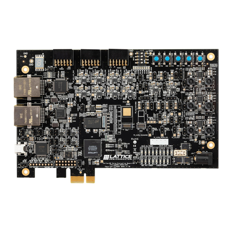
Figure 1.1. Top View of DisplayPort VIP Input Board ...........................................................................................................4
Figure 1.2. Bottom View of DisplayPort VIP Input Board .....................................................................................................5
Figure 2.1 Functional Block Diagram ....................................................................................................................................6
Figure 4.1 Power Supply .......................................................................................................................................................9
Figure A.1. Block Diagram...................................................................................................................................................13
Figure A.2. DP Redriver and Connector I/F .........................................................................................................................14
Figure A.3. Power, Debug LED, Header I/F .........................................................................................................................15
Figure A.4. Clock Synthesizer ..............................................................................................................................................16
Tables
Table 3.1. Connector J1 ........................................................................................................................................................7
Table 3.2. Connector J2 ........................................................................................................................................................8
Table 5.1 User LEDs.............................................................................................................................................................10
Table 8.1. Reference Part Number .....................................................................................................................................11
