Lattice MachXO3D Breakout Board User manual

MachXO3D Breakout Board
User Guide
FPGA-UG-02084-0.90
July 2019

MachXO3D Breakout Board
User Guide
© 2019 Lattice Semiconductor Corp. All Lattice trademarks, registered trademarks, patents, and disclaimers are as listed at www.latticesemi.com/legal.
All other brand or product names are trademarks or registered trademarks of their respective holders. The specifications and information herein are subject to change without notice.
2 FPGA-UG-02084-0.90
Disclaimers
Lattice makes no warranty, representation, or guarantee regarding the accuracy of information contained in this document or the suitability of its
products for any particular purpose. All information herein is provided AS IS and with all faults, and all risk associated with such information is entirely
with Buyer. Buyer shall not rely on any data and performance specifications or parameters provided herein. Products sold by Lattice have been
subject to limited testing and it is the Buyer's responsibility to independently determine the suitability of any products and to test and verify the
same. No Lattice products should be used in conjunction with mission- or safety-critical or any other application in which the failure of Lattice’s
product could create a situation where personal injury, death, severe property or environmental damage may occur. The information provided in this
document is proprietary to Lattice Semiconductor, and Lattice reserves the right to make any changes to the information in this document or to any
products at any time without notice.

MachXO3D Breakout Board
User Guide
© 2019 Lattice Semiconductor Corp. All Lattice trademarks, registered trademarks, patents, and disclaimers are as listed at www.latticesemi.com/legal.
All other brand or product names are trademarks or registered trademarks of their respective holders. The specifications and information herein are subject to change without notice.
FPGA-UG-02084-0.90 3
Contents
Acronyms in This Document.................................................................................................................................................5
1. Introduction..................................................................................................................................................................6
2. Features........................................................................................................................................................................7
3. Storage and Handling ...................................................................................................................................................9
4. Software Requirements..............................................................................................................................................10
5. MachXO3D Device ......................................................................................................................................................11
6. Demonstration Design................................................................................................................................................12
6.1. Running the Demonstration Design ..................................................................................................................12
6.2. Download Demo Designs ..................................................................................................................................13
6.3. Programming a Demo Design with the Lattice Diamond Programmer.............................................................14
7. MachXO3D Breakout Board........................................................................................................................................15
7.1. Overview ...........................................................................................................................................................15
7.2. Subsystems........................................................................................................................................................16
7.2.1. Clock Sources ................................................................................................................................................16
7.2.2. Expansion Header Landings ..........................................................................................................................16
7.2.3. MachXO3D FPGA ..........................................................................................................................................22
7.2.4. Programming Interface Circuits....................................................................................................................22
7.2.5. LEDs...............................................................................................................................................................23
7.2.6. Power Supply ................................................................................................................................................23
7.2.7. Test Points ....................................................................................................................................................23
7.2.8. USB Programming and Debug Interface .......................................................................................................23
7.3. Board Modifications..........................................................................................................................................24
7.3.1. Bypassing the USB Programming Interface ..................................................................................................24
7.3.2. Applying External Power...............................................................................................................................24
7.3.3. Measuring Bank and Core Power .................................................................................................................24
7.4. Mechanical Specifications.................................................................................................................................24
7.5. Environmental Requirements ...........................................................................................................................24
8. Troubleshooting .........................................................................................................................................................25
8.1. LEDs Do Not Flash .............................................................................................................................................25
8.2. USB Cable Not Detected ...................................................................................................................................25
8.3. Determine the Source of a Pre-programmed Device........................................................................................25
9. Ordering Information .................................................................................................................................................26
Schematics................................................................................................................................................27
Bill of Materials.........................................................................................................................................35
References..........................................................................................................................................................................37
Lattice Semiconductor Documents.................................................................................................................................37
Revision History ..................................................................................................................................................................38
MachXO3D Breakout Board
User Guide
© 2019 Lattice Semiconductor Corp. All Lattice trademarks, registered trademarks, patents, and disclaimers are as listed at www.latticesemi.com/legal.
All other brand or product names are trademarks or registered trademarks of their respective holders. The specifications and information herein are subject to change without notice.
4 FPGA-UG-02084-0.90
Figures
Figure 2.1. MachXO3D Breakout Board, Top Side ................................................................................................................7
Figure 2.2. MachXO3D Breakout Board, Bottom Side ..........................................................................................................8
Figure 6.1.Demonstration Design Block Diagram ...............................................................................................................12
Figure 7.1. MachXO3D-9400HC Block Diagram ..................................................................................................................15
Figure 7.2. J3/J4 Header Landing Callout............................................................................................................................21
Figure 7.3. J6/J8 Header Landing Callout............................................................................................................................21
Figure 7.4. J1 Header Landing and LED Array Callout.........................................................................................................22
Figure A.1. Block Diagram...................................................................................................................................................27
Figure A.2. USB to JTAG Interface.......................................................................................................................................28
Figure A.3. Power Regulators .............................................................................................................................................29
Figure A.4. Bank0 I/O..........................................................................................................................................................30
Figure A.5. Bank1 I/O..........................................................................................................................................................31
Figure A.6. Bank2 I/O..........................................................................................................................................................32
Figure A.7. Bank3, 4, 5 I/O ..................................................................................................................................................33
Figure A.8. Power Decoupling and LEDs .............................................................................................................................34
Tables
Table 6.1. DIP Switch Setting and LED Behavior .................................................................................................................12
Table 7.1. MachXO3D Breakout Board Components and Interfaces..................................................................................16
Table 7.2. Expansion Connector Reference ........................................................................................................................16
Table 7.3. Expansion Header Pin Information for Bank 0 (J3) ............................................................................................17
Table 7.4. Expansion Header Pin Information for Bank 1 (J4) ............................................................................................18
Table 7.5. Expansion Header Pin Information for Bank 2 (J6) ............................................................................................19
Table 7.6. Expansion Header Pin Information for Bank 3/4/5 (J8) .....................................................................................20
Table 7.7. MachXO3D FPGA Interface Reference...............................................................................................................22
Table 7.8. USB/JTAG Interface Reference...........................................................................................................................22
Table 7.9. JTAG Programming Pin Information...................................................................................................................22
Table 7.10. SPI Programming Pin Information....................................................................................................................23
Table 7.11. I2 Programming Pin Information......................................................................................................................23
Table 7.12. Power and User LEDs Reference ......................................................................................................................23
Table 7.13. USB Interface Reference ..................................................................................................................................23
Table B.1. MachXO3D Breakout Board Bill of Materials.....................................................................................................35

MachXO3D Breakout Board
User Guide
© 2019 Lattice Semiconductor Corp. All Lattice trademarks, registered trademarks, patents, and disclaimers are as listed at www.latticesemi.com/legal.
All other brand or product names are trademarks or registered trademarks of their respective holders. The specifications and information herein are subject to change without notice.
FPGA-UG-02084-0.90 5
Acronyms in This Document
A list of acronyms used in this document.
Acronym
Definition
DIP
Dual in-line Package
ESB
Embedded Security Block
FPGA
Field Programmable Gate Array
FTDI
Future Technology Devices International
I2C
Inter-Integrated Circuit
LED
Light Emitting Diode
LUT
Look Up Table
PCB
Printed Circuit Board
RoHS
Restriction of Hazardous Substances Directive
SPI
Serial Peripheral Interface
USB
Universal Serial Bus
WDT
Watchdog Timer
DNI
Do Not Install

MachXO3D Breakout Board
User Guide
© 2019 Lattice Semiconductor Corp. All Lattice trademarks, registered trademarks, patents, and disclaimers are as listed at www.latticesemi.com/legal.
All other brand or product names are trademarks or registered trademarks of their respective holders. The specifications and information herein are subject to change without notice.
6 FPGA-UG-02084-0.90
1. Introduction
This user guide describes how to start using the MachXO3D™Breakout Board, hereinafter referred to as the Board. It is
an easy-to-use platform for evaluating and designing with the MachXO3D device, a secure control PLD from Lattice
Semiconductor. Along with the Board and accessories, a preloaded demonstration design is included. You may also
reprogram the onboard MachXO3D device to review your own custom designs.
The MachXO3D Breakout Board currently features a Flash-based MachXO3D-9400HC device in a 256-ball 0.8 mm pitch
caBGA package. The Board includes a serial Flash memory for demonstrating external SPI boot-up. The external Flash
memory also supports one of the dual-boot modes in addition to on chip dual-boot configuration memory. For more
details regarding the supported dual-boot mode, refer to MachXO3D Programming and Configuration Usage Guide
(FPGA-TN-02069).
See also the Ordering Information section for more information.
Note: Static electricity can severely shorten the lifespan of electronic components. See the Storage and Handling
section of this document for handling and storage tips.

MachXO3D Breakout Board
User Guide
© 2019 Lattice Semiconductor Corp. All Lattice trademarks, registered trademarks, patents, and disclaimers are as listed at www.latticesemi.com/legal.
All other brand or product names are trademarks or registered trademarks of their respective holders. The specifications and information herein are subject to change without notice.
FPGA-UG-02084-0.90 7
2. Features
The MachXO3D Breakout Kit includes:
MachXO3D Breakout Board –The Board is a 3” × 3” form factor that features the following onboard components
and circuits:
MachXO3D FPGA – Flash-based LCMXO3D-9400HC-5BG256C
USB mini-B connector for power and programming
16 Mb Serial Flash Memory (Machronix MX25V1635) for external SPI boot up support
Eight LEDs
Four-position DIP switch
Momentary push button switch
40-hole prototype area
Four 2 × 20 expansion header landings for general I/O, JTAG, and external power
1 × 8 expansion header landing for JTAG
1 × 6 expansion header landing for SPI/I2C
3.3 V and 1.2 V supply rails
Preloaded Demo –The Board includes a preloaded counter design that highlights use of the embedded MachXO3D
oscillator and programmable I/O configured for LED drive.
USB Connector Cable –The Board is powered from the USB mini-B socket when connected to a host PC. The USB
channel also provides a programming interface to the MachXO3D JTAG port.
Lattice Development Kits and Boards Web Page –Visit www.latticesemi.com/boards, and look for the MachXO3D
Breakout Board for the latest documentation including this guide and other downloads supporting this board. This
user guide includes demo operation, programming instructions, top-level functional descriptions of the MachXO3D
Breakout Board, descriptions of the on-board connectors, and a complete set of schematics.
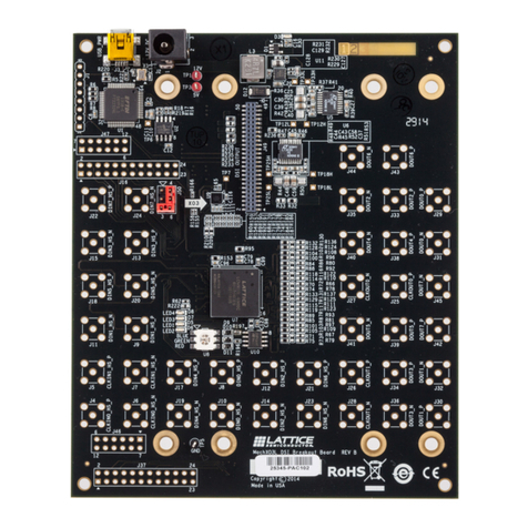
Figure 2.1 and Figure 2.2 show the top side and bottom side of the MachXO3D Breakout board.
Two 2 x 20 Header
Landings (J3, J4)
Two 2 x 20 Header
Landings (J6, J8)
JTAG Header
Landing (J1)
SPI/I2C Header
Landing (J7)
MachXO3D PLD
(U5)
USB Mini-B
Socket (J2)
Power LED,
Blue (D1)
FTDI USB to
UART/FIFO IC (U1)
Push Button
Switch (SW1)
4-Position DIP
Switch (SW2)
4 x 10 40-Hole
Prototype array
LED array
(D9 -D2)
Figure 2.1. MachXO3D Breakout Board, Top Side

MachXO3D Breakout Board
User Guide
© 2019 Lattice Semiconductor Corp. All Lattice trademarks, registered trademarks, patents, and disclaimers are as listed at www.latticesemi.com/legal.
All other brand or product names are trademarks or registered trademarks of their respective holders. The specifications and information herein are subject to change without notice.
8 FPGA-UG-02084-0.90
SPIFlash Boot
Memory (U6)
Figure 2.2. MachXO3D Breakout Board, Bottom Side

MachXO3D Breakout Board
User Guide
© 2019 Lattice Semiconductor Corp. All Lattice trademarks, registered trademarks, patents, and disclaimers are as listed at www.latticesemi.com/legal.
All other brand or product names are trademarks or registered trademarks of their respective holders. The specifications and information herein are subject to change without notice.
FPGA-UG-02084-0.90 9
3. Storage and Handling
Static electricity can shorten the lifespan of electronic components. Follow the tips below to prevent damage that
could occur from electrostatic discharge:
Use anti-static precautions such as operating on an anti-static mat and wearing an anti-static wristband.
Store the evaluation board in the packaging provided.
Touch a metal USB housing to equalize voltage potential between you and the Board.

MachXO3D Breakout Board
User Guide
© 2019 Lattice Semiconductor Corp. All Lattice trademarks, registered trademarks, patents, and disclaimers are as listed at www.latticesemi.com/legal.
All other brand or product names are trademarks or registered trademarks of their respective holders. The specifications and information herein are subject to change without notice.
10 FPGA-UG-02084-0.90
4. Software Requirements
Before you begin developing new designs for the MachXO3D Breakout Board, install the Lattice Diamond® design
software. For detailed information on the Diamond software, visit www.latticesemi.com/diamond.
Diamond software includes the Lattice Diamond Programmer for programming your own content to the MachXO3D
FPGA. Lattice Diamond Programmer is also available as a stand-alone installation at www.latticesemi.com/programmer
Note: To communicate with the Board, FTDI Chip USB hardware drivers are required. It can be installed as an option
within the Diamond or Diamond Programmer installation.

MachXO3D Breakout Board
User Guide
© 2019 Lattice Semiconductor Corp. All Lattice trademarks, registered trademarks, patents, and disclaimers are as listed at www.latticesemi.com/legal.
All other brand or product names are trademarks or registered trademarks of their respective holders. The specifications and information herein are subject to change without notice.
FPGA-UG-02084-0.90 11
5. MachXO3D Device
The Board currently features the MachXO3D-9400HC FPGA which enhances Secure Control PLD functionality with
Hardware Root-of-Trust and Dual Boot capabilities. It features an immutable Embedded Security Block which offers
cryptographic functions such as ECDSA256, SHA256, HMAC, ECIES, ECDH, AES-128/256, PUF, Public/Private Key
Generation, and True Random Number Generator. Along with Embedded Security Block (ESB), numerous system
functions are included, such as two PLLs, 432 kbits of embedded RAM, plus hardened implementations of I2C and SPI.
Flexible, high performance I/O supports numerous single-ended and differential standards including LVDS. The 256-ball
BGA package provides up to 206 user I/O in a 14 mm × 14 mm form factor. A complete description of this MachXO3D
device can be found in the MachXO3D Device Family Data Sheet (FPGA-DS-02026).

MachXO3D Breakout Board
User Guide
© 2019 Lattice Semiconductor Corp. All Lattice trademarks, registered trademarks, patents, and disclaimers are as listed at www.latticesemi.com/legal.
All other brand or product names are trademarks or registered trademarks of their respective holders. The specifications and information herein are subject to change without notice.
12 FPGA-UG-02084-0.90
6. Demonstration Design
Lattice provides a simple, pre-programmed demo to illustrate basic operation of the MachXO3D device. The design
integrates an LED controller with the on-chip oscillator or external clock. The pre-programmed design resides in the
internal Flash.
Note: To restore the factory default demo and program it with other Lattice-supplied examples, see the Download
Demo Designs section of this document.
6.1. Running the Demonstration Design
Figure 6.1 is the block diagram of the demonstration design. Upon power-up, the preprogrammed demonstration
design automatically loads and drives the LED array in a 1-Hz pattern. The program shows a clock divider driven by
either the MachXO3D internal oscillator or the external FTDI clock chip. The divider modules, heartbeat.v and kitcar.v,
are clocked at the default frequency of 12 MHz, which divides the clock to cycle the LED display approximately once per
second. The resulting light pattern is determined by the DIP Switch (SW2) setting as shown in Table 6.1.
MachXO3D Device
X1
12.0 MHz
OSCH
12.09 MHz Kitcar.v
Heartbeat.v
SW2
4-Position DIPSW
1 x 8
LED
Array
XO3D_BB_blink.v
SW1
Momentary PB Async Reset
Figure 6.1.Demonstration Design Block Diagram
Table 6.1. DIP Switch Setting and LED Behavior
Switch
Setting
LED Behavior
DIP_SW[1]
0 (Down)
External 12.0 MHz (X1)
1 (Up)
Internal 12.09 MHz (OSCJ)
DIP_SW[2:4]
001
1 Hz Sweep
011
1 Hz Left-Right
111
1 Hz Blink
Others
1 Hz Alternating
WARNING: Do not connect the Board to your PC before you complete the driver installation procedure of this section.
Communication between the Board and a PC through the USB connection cable requires installation of the FTDI Chip
USB hardware drivers. Loading these drivers enables the computer to recognize and program the Board. Drivers can be
loaded as part of the installation of Lattice Diamond design software or Diamond Programmer, or as a stand-alone
package.

MachXO3D Breakout Board
User Guide
© 2019 Lattice Semiconductor Corp. All Lattice trademarks, registered trademarks, patents, and disclaimers are as listed at www.latticesemi.com/legal.
All other brand or product names are trademarks or registered trademarks of their respective holders. The specifications and information herein are subject to change without notice.
FPGA-UG-02084-0.90 13
To load the FTDI Chip USB hardware drivers as part of the Lattice Diamond installation:
1. Select Programmer Drivers in the Product Options of Lattice Diamond Setup.
2. Select FTDI Windows USB Driver or All Drivers in the LSC Drivers Install/Uninstall dialog box.
3. Click Finish to install the USB driver.
4. After the driver installation is completed, connect the USB cable from a USB port on your PC to the Board USB
mini-B socket (J2). After the connection is made, a blue Power LED (D1) lights indicating the Board is powered on.
5. The demonstration design automatically loads and drive the LED array in a repeating pattern.
To load the FTDI Chip USB hardware drivers through the stand-alone package on a Windows system:
1. Download the FTDI Chip USB hardware driver package from Lattice web site.
2. Extract the FTDI Chip USB hardware driver package to your PC hard drive.
3. Connect the USB cable from a USB port on your PC to the Board USB mini-B socket (J2). After the connection is
made, a blue Power LED (D1) lights indicating the Board is powered on.
4. If you are prompted Windows may connect to Windows Update select No, not this time from available options and
click Next to proceed with the installation.
5. Choose the Install from specific location (Advanced) option and click Next.
6. Search for the best driver in these locations and click the Browse button to browse to the Windows driver folder.
Select the CDM 2.04.06 WHQL Certified folder and click OK.
7. Click Next. A screen displays as Windows copies the required driver files. Windows displays a message indicating
that the installation is successful.
8. Click Finish to install the USB driver.
9. The demonstration design is automatically loaded and drives the LED array in a repeating pattern.
See the Troubleshooting section of this guide if the Board does not function as expected.
6.2. Download Demo Designs
The LED controller demo is pre-programmed into the Board, however, over time it is likely your board is modified.
Lattice distributes source and programming files for demonstration designs compatible with the MachXO3D Breakout
Board. The demo design for the Board is available on Lattice website.
To download demo designs:
1. Go to www.latticesemi.com/boards. Navigate to the MachXO3D Breakout Board web page. In the Documentation
section, from the Downloads area, click Design File. From the drop-down list, select MachXO3D Breakout Board
Program and save the file.
2. Extract the contents of MachXO3D_Breakout_Brd.zip to an accessible location on your hard drive.
3. Open the project file Blink.ldf in the Lattice Diamond design software.
4. Run the Process Flow and regenerate the Bitstream file.
After downloading demo designs, you can follow steps in the Programming a Demo Design with the Lattice Diamond
Programmer section to program a demo design.

MachXO3D Breakout Board
User Guide
© 2019 Lattice Semiconductor Corp. All Lattice trademarks, registered trademarks, patents, and disclaimers are as listed at www.latticesemi.com/legal.
All other brand or product names are trademarks or registered trademarks of their respective holders. The specifications and information herein are subject to change without notice.
14 FPGA-UG-02084-0.90
6.3. Programming a Demo Design with the Lattice Diamond Programmer
The demonstration design is pre-programmed into the MachXO3D Breakout Board by Lattice Semiconductor. If you
have changed the design but now want to restore the Board to factory settings, follow the steps below.
To program the MachXO3D device:
1. Install, license, and run Lattice Diamond software. See Lattice Diamond for downloading and licensing information.
2. Connect the USB cable to the host PC and the MachXO3D Breakout Board.
3. From Diamond, open the project file Blink.ldf.
4. Double click impl.xcf under Programming Files of imple1 to open the embedded Programmer.
5. Click the Program icon. When the process is completed, PASS is displayed in the Status column.
You can also use the stand-alone Diamond Programmer to update the MachXO3D device.
1. Click the Programmer icon.
2. Click Detect Cable. The Programmer detects the cable HW-USBN-2B, Port: FTUSB-0. If the cable is not detected, see
the Troubleshooting section.
3. Click Device Properties.
4. Make sure the default Access mode is Flash Programming Mode, the default Port Interface is JTAG Interface, and
the default Operation is Flash Erase, Program, Verify.
5. Check the Flash_A Programming Options, and select Blink_impl1_a.jed programming file before clicking OK.
6. Click the Program icon. When the process is completed, PASS is displayed in the Status column.

MachXO3D Breakout Board
User Guide
© 2019 Lattice Semiconductor Corp. All Lattice trademarks, registered trademarks, patents, and disclaimers are as listed at www.latticesemi.com/legal.
All other brand or product names are trademarks or registered trademarks of their respective holders. The specifications and information herein are subject to change without notice.
FPGA-UG-02084-0.90 15
7. MachXO3D Breakout Board
This section describes the features of the MachXO3D Breakout Board in detail.
7.1. Overview
The MachXO3D Breakout Board is a complete development platform for the MachXO3D FPGA. The Board includes a
prototyping area, a USB program/power port, an LED array, switches, and header landings with electrical connections
to most of the FPGA programmable I/O, power, and configuration pins. The Board is powered by the PC USB port or
optionally with external power. You may create or modify the program files and reprogram the Board using Lattice
Diamond software.
MachXO3D-9400HC Device
2 x 20 Header
Landing (J6)
LED
Array
GPIO
8
2 x 20 Header
Landing (J3)
GPIO 2 x 20 Header
Landing (J4)
Bank 1
Bank 2
Bank 0
Landing (J8)
GPIO
GPIO
USB
Controller
USB Mini B
Socket
1 x 8 Header
Landing (J1,
Optional JTAG
Interface)
JTAG
Programming
1 x 6 Header
Landing (J7,
Optional SPI,
I2C Interfaces)
Bank 0, 2
DIP_SW 4
Bank 3, 4, and 5
Figure 7.1. MachXO3D-9400HC Block Diagram

MachXO3D Breakout Board
User Guide
© 2019 Lattice Semiconductor Corp. All Lattice trademarks, registered trademarks, patents, and disclaimers are as listed at www.latticesemi.com/legal.
All other brand or product names are trademarks or registered trademarks of their respective holders. The specifications and information herein are subject to change without notice.
16 FPGA-UG-02084-0.90
Table 7.1. MachXO3D Breakout Board Components and Interfaces
Component/Interface
Type
Schematic Reference
Description
Circuits
USB Controller
Circuit
U1: FT2232H
USB-to-JTAG interface and dual USB UART/FIFO IC
USB Mini-B Socket
I/O
J2:USB_MINI_B
Programming and debug interface
Components
LCMXO3D
FPGA
U5: LCMXO3D-
9400HC-5BG256C
9400-LUT device packaged in a 14 mm × 14 mm, 256-ball caBGA
Interfaces
LED Array
Output
D9-D2
Red LEDs
Push Button Switch
Input
SW1
Momentary User Input
4-position DIP Switch
Input
SW2
User inputs
Four 2 x 20 Header
Landings
I/O
J3: header_2x20
J4: header_2x20
J6: header_2x20
J8: header_2x20
User-definable I/O
1 x 8 Header Landing
I/O
J1: header_1x8
Optional JTAG interface
1 x 6 Header Landing
I/O
J7: header_1x6
Optional SPI/I2C interfaces
4 x 10 40-Hole Prototype
Area
—
—
Prototype area 100 mil centered holes.
Test Points
Power
TP1: +3.3 V
TP2: +1.2 V
TP3: GND
Power and ground reference points
7.2. Subsystems
This section describes the principle subsystems for the MachXO3D Breakout Board in alphabetical order.
7.2.1. Clock Sources
Clock sources for the LED demonstration designs originate from the MachXO3D on-chip oscillator or the 12 MHz crystal
X1. You may use an expansion header landing to drive an FPGA input with an external clock source.
7.2.2. Expansion Header Landings
The expansion header landings provide access to user GPIOs, primary inputs, clocks, and VCCO pins of the MachXO3D
device. The remaining pins serve as power supplies for external connections. Each landing is configured as one 2 × 20
100 mil.
Table 7.2. Expansion Connector Reference
Item
Description
Reference Designators
J3, J4, J6, J8
Part Number
header_2x20

MachXO3D Breakout Board
User Guide
© 2019 Lattice Semiconductor Corp. All Lattice trademarks, registered trademarks, patents, and disclaimers are as listed at www.latticesemi.com/legal.
All other brand or product names are trademarks or registered trademarks of their respective holders. The specifications and information herein are subject to change without notice.
FPGA-UG-02084-0.90 17
Table 7.3. Expansion Header Pin Information for Bank 0 (J3)
Header Pin Number
–9400HC Function
MachXO3D Ball in 256caBGA
1
VCCIO0
D5,D12,G8,G9
2
VCCIO0
D5,D12,G8,G9
3
PT44C/INITn
A13
4
PT44D/DONE
C13
5
PT27A
F8
6
PT43B
B12
7
PT43A
C12
8
PT29B
E11
9
PT31B
E10
10
PT31A
D10
11
GND
—
12
GND
—
13
PT29A
F9
14
PT31C/JTAGENB
C10
15
PT22B
E8
16
PT24B
E9
17
PT15B
E7
18
PT24A
D8
19
PT21B
D7
20
PT20B
C7
21
GND
—
22
GND
—
23
PT10B
C5
24
PT15A
D6
25
PT21A
E6
26
PT9A
C4
27
PT28B
A10
28
PT22A
F7
29
PT27B
D9
30
PT28A
B9
31
GND
—
32
GND
—
33
PT11B
B6
34
PT20A
B7
35
PT9B
B5
36
PT11A
A5
37
PT12B
B4
38
PT10A
A4
39
GND
—
40
PT12A
A3

MachXO3D Breakout Board
User Guide
© 2019 Lattice Semiconductor Corp. All Lattice trademarks, registered trademarks, patents, and disclaimers are as listed at www.latticesemi.com/legal.
All other brand or product names are trademarks or registered trademarks of their respective holders. The specifications and information herein are subject to change without notice.
18 FPGA-UG-02084-0.90
Table 7.4. Expansion Header Pin Information for Bank 1 (J4)
Header Pin Number
–9400HC Function
MachXO3D Ball in 256caBGA
1
VCCIO1
E13,H10,J10,M13
2
VCCIO1
E13,H10,J10,M13
3
PR24D
K12
4
PR24C
K13
5
PR28A
M14
6
PR29B
N14
7
PR21B
L14
8
PR29A
N16
9
PR28B
M15
10
PR25B
M16
11
GND
—
12
GND
—
13
PR25A
L15
14
PR21A
L16
15
PR20A
K14
16
PR19B
K16
17
PR20B
K15
18
PR18B
J14
19
PR17A/PCLKT1_0
H14
20
PR19A
J15
21
GND
—
22
GND
—
23
PR18A
J16
24
PR16B
H15
25
PR17B/PCLKC1_0
H16
26
PR12A
G15
27
PR16A
G16
28
PR5B
F15
29
PR7B
F16
30
PR2B/R_GPLLC_FB
E15
31
GND
—
32
GND
—
33
PR5A
E16
34
PR3B/R_GPLLC_IN
E14
35
PR3A/R_GPLLT_IN
D16
36
PR2C
C15
37
PR2A/R_GPLLT_FB
D14
38
PR7A
F14
39
PR12B
G14
40
PR2D
B16

MachXO3D Breakout Board
User Guide
© 2019 Lattice Semiconductor Corp. All Lattice trademarks, registered trademarks, patents, and disclaimers are as listed at www.latticesemi.com/legal.
All other brand or product names are trademarks or registered trademarks of their respective holders. The specifications and information herein are subject to change without notice.
FPGA-UG-02084-0.90 19
Table 7.5. Expansion Header Pin Information for Bank 2 (J6)
Header Pin Number
–9400HC Function
MachXO3D Ball in 256caBGA
1
VCCIO2
K8,K9,N5,N12
2
VCCIO2
K8,K9,N5,N12
3
PB43B
T12
4
PB41B
T14
5
PB43A
R11
6
PB41A
R13
7
PB35A
T11
8
PB32B
M11
9
PB35B
P11
10
PB32A
N10
11
GND
—
12
GND
—
13
PB30B
T10
14
PB33A
P10
15
PB30A
R9
16
PB33B
R10
17
PB29A/PCLKT2_1
T9
18
PB27B
N9
19
PB29B/PCLKC2_1
P9
20
PB27A
M8
21
GND
—
22
GND
—
23
PB24B
T8
24
PB21B
L8
25
PB24A
P8
26
PB21A
M6
27
PB18A
R7
28
PB22B/PCLKC2_0
R8
29
PB18B
P7
30
PB22A/PCLKT2_0
T7
31
GND
—
32
GND
—
33
PB13B
L7
34
PB10B
R6
35
PB13A
N6
36
PB10A
T5
37
PB8B
R4
38
PB5A
P4
39
PB8A
T3
40
PB5B
T4

MachXO3D Breakout Board
User Guide
© 2019 Lattice Semiconductor Corp. All Lattice trademarks, registered trademarks, patents, and disclaimers are as listed at www.latticesemi.com/legal.
All other brand or product names are trademarks or registered trademarks of their respective holders. The specifications and information herein are subject to change without notice.
20 FPGA-UG-02084-0.90
Table 7.6. Expansion Header Pin Information for Bank 3/4/5 (J8)
Header Pin Number
–9400HC Function
MachXO3D Ball in 256caBGA
1
VCCIO5
E4
2
VCCIO3
M4
3
PL30B
N3 (Bank 3)
4
PL12D
H6 (Bank 5)
5
PL30A
M2 (Bank 3)
6
PL29B
N1 (Bank 3)
7
PL29A
M3 (Bank 3)
8
PL27B/PCLKC3_0
M1 (Bank 3)
9
PL27A/PCLKT3_0
L2 (Bank 3)
10
PL25A
L1 (Bank 3)
11
GND
—
12
GND
—
13
PL25B
L3 (Bank 3)
14
PL16A/PCLKT4_0
J1 (Bank 4)
15
PL17B
K1 (Bank 4)
16
PL17A
J2 (Bank 4)
17
PL16B/PCLKC4_0
J3 (Bank 4)
18
PL14A
H3 (Bank 4)
19
PL13B
H2 (Bank 4)
20
PL14B
H1 (Bank 4)
21
GND
—
22
GND
—
23
PL12A
G2 (Bank 5)
24
PL13A
G1 (Bank 4)
25
PL7B/PCLKC5_0
F2 (Bank 5)
26
PL11B
F1 (Bank 5)
27
PL4A/L_GPLLT_IN
E2 (Bank 5)
28
PL7A/PCLKT5_0
E1 (Bank 5)
29
PL4D
D2 (Bank 5)
30
PL3B/L_GPLLC_FB
D1 (Bank 5)
31
GND
—
32
PL2D
C2 (Bank 5)
33
PL4C
C1 (Bank 5)
34
PL12B
G3 (Bank 5)
35
PL2C
B1 (Bank 5)
36
PL3A/L_GPLLT_FB
D3 (Bank 5)
37
PL4B/L_GPLLC_IN
E3 (Bank 5)
38
PL11A
F3 (Bank 5)
39
PL12C
F5 (Bank 5)
40
VCCIO4
H7,J7
Table of contents
Other Lattice Motherboard manuals

Lattice
Lattice DisplayPort VIP Input Board User manual

Lattice
Lattice LCMXO3L-DSI-EVN User manual

Lattice
Lattice ORCA ORT42G5 Instruction Manual

Lattice
Lattice ORCA ORSO42G5 Instruction Manual

Lattice
Lattice iCEblink40-HX1K User manual

Lattice
Lattice Certus-NX Versa User manual

Lattice
Lattice iCE40 UltraPlus 8:1 Mic Aggregation Demo User manual

Lattice
Lattice CrossLink LIF-MD6000 Master Link Board - Revision... User manual

Lattice
Lattice Certus-NX User manual

Lattice
Lattice MachXO2280 User manual