Lauterbach PowerTrace Serial User manual

PowerTrace Serial User´s Guide 1
©1989-2018 Lauterbach GmbH
PowerTrace Serial User´s Guide
TRACE32 Online Help
TRACE32 Directory
TRACE32 Index
TRACE32 Documents ......................................................................................................................
PowerTrace Serial User´s Guide .................................................................................................. 1
History ......................................................................................................................................... 3
Introduction ................................................................................................................................ 3
Intended Audience 3
Prerequisites 3
Contacting Support 4
Installation .................................................................................................................................. 5
Hardware Installation 5
PowerTrace Serial 5
Adapter for AGBT (LA-3556) 8
Adapter for RH850 (LA-3561) 9
Adapter for Mini-PCIe (LA-3526) 11
Adapter for PCIe Slot Card (LA-3525) 12
Configuration Switches 17
Configuration Guide 20
Software Installation 21
Recommendation for the Software Start 21
Recommendation for Power Down 21
Trace Port Utilization ................................................................................................................. 22
HSSTP-based Trace Port 22
Start-up Script 23
Example 23
AGBT-based Trace Port 27
Serial NEXUS-based Trace Port 27
PCIe-based Trace Port 27
Start-up Script 28
Example 28
FAQ .............................................................................................................................................. 30
Diagnosis .................................................................................................................................... 31
Device LED Codes 31
POWER 31
SELECT 31

PowerTrace Serial User´s Guide 2
©1989-2018 Lauterbach GmbH
RECORD 31
RUNNING 31
Displaying Error Messages 32
Searching for Errors 33
Types of Trace Decoder Errors 35
Harderror 35
Flowerror 35
Fifofull 36
Trace Test Failure Messages 36
Diagnosis Check List 37
Basic Checks 37
Advanced Checks 41
Recommendations for Target Board Design 42
Technical Data ............................................................................................................................ 43
PowerTrace Serial Accessory Sets 43
LA-3521 - ACC-PTSERIAL-ETM 1-6 43
LA-1235 - 40pin Flex Cable 43
LA-2770 - Mipi34-ARM20 Adapter 44
LA-2114 - 34pin Half Size Cable 44
LA-3522 - ACC-PTSERIAL-ETM 7-8 45
LA-1239 - 80pin Flex Cable 45
Electrical Specification for PowerTrace Serial 46
Electrical Characteristics 46
Absolute Maximum Ratings 46
Switching Characteristics 46
Timing Characteristics 47
Maximum Lane Skew 47
Additional Data 47
PCB 47
Device Connector 47
Simulation Model 48
Simulation Data Request 48
PowerTrace Serial 48
Dimensions 48
Connector Layout 48
SerialPort 0 48
SerialPort 1 48
DEBUG 49

PowerTrace Serial User´s Guide 3
©1989-2018 Lauterbach GmbH
PowerTrace Serial User´s Guide
Version 14-Nov-2018
History
05-Feb-18 New manual.
Introduction
Lauterbach Development has enlarged its trace tool portfolio for serial trace ports. The new device called
PowerTrace Serial extends the range of supported lane data rates to 12.5Gbps and the possible lane count
up to eight. Furthermore, new interfaces are supported e.g. PCIe, which allow trace data transfer over
common interfaces.
PowerTrace Serial is not just the successor of the serial preprocessor. The well know serial preprocessor in
conjunction with the PowerTrace 2 is still the preferred tool for low speed and low lane count applications.
However in case of lane speeds above 6Gbps and/or lane counts higher than four, the PowerTrace Serial will
be the preferred tool.
Higher speeds are always combined with higher demand on system design. New interfaces require digging
into new papers of peripheral components. There is more work to do and higher potential of malfunction.
This User’s Guide intends to flatten the path to a well working Gigabit-trace setup.
Intended Audience
This manual categorizes users into the following groups:
•Serial trace average users: In addition to reading chapter Installation, they should focus on the
sections Trace Port Utilization and Basic Checks.
•Serial trace advanced users: As they are familiar with the above chapters and sections,
advanced users should also read the sections Advanced Checks.
Prerequisites
• This document assumes that you already have the PowerTrace Serial hardware and a fully
functional TRACE32 software installation.
• For some trace port types (e.g. PCIe), you need a different accessory set.

PowerTrace Serial User´s Guide 4
©1989-2018 Lauterbach GmbH
Contacting Support
Be sure to include detailed system information about your TRACE32 configuration.
1. To generate a system information report, choose TRACE32 > Help > Support > Systeminfo.
2. Preferred: click Save to File, and send the system information as an attachment to your e-mail.
3. Click Save to Clipboard, and then paste the system information into your e-mail.
Support Address
In addition to the system information report, please send the following information and files to
icrstp-support@lauterbach.com:
• Used start-up/configuration scripts
• List of all TRACE32 device, adapters and cables.
• A picture of your complete trace/debug hardware setup, if possible.
• The complete text of the error messages you get (AREA.view)
• Trace connector pinout (board schematics and layout)
• Is the problem lane speed or lane count dependent?
• A screenshot of each lane shown in Trace.ShowFocusEye (press SCAN before)
NOTE: Please help to speed up processing of your support request. By filling out the
system information form completely and with correct data, you minimize the
number of additional questions and clarification request e-mails we need to
resolve your problem.

PowerTrace Serial User´s Guide 5
©1989-2018 Lauterbach GmbH
Installation
In this section:
•Hardware Installation
•Software Installation
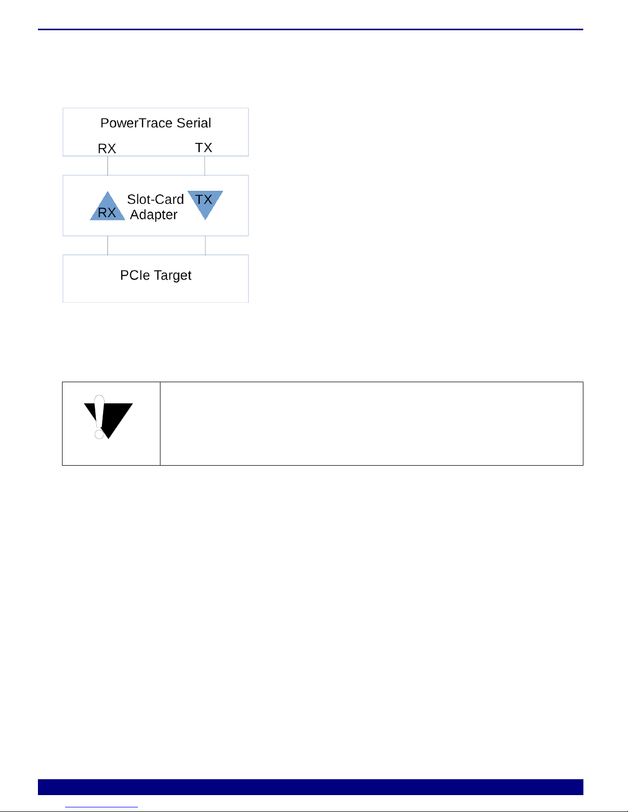
Hardware Installation
PowerTrace Serial
1. Connect the PODBUS EXPRESS IN connector to the PODBUS EXPRESS OUT connector of
the PowerDebug II / PowerDebug Pro interface. Please ensure correct positioning. The
connectors must be clean and without any damage.
2. Connect the flex cable and, if necessary, the debug cable to Serial Port 0 or Serial Port 1 of the
PowerTrace Serial.
Check the connector orientation of tool and target, there are two 45° corners [A] and two 90° corners
[B]:
The marker of pin 1 [C] of the plug is easy to miss, but is located close to one 45° corner [A]. For
better illustration the picture below is rotated of 180°:
A45° conners B90° conners
CPin 1 marker
AAA
A
BB B
B
C
A
B

PowerTrace Serial User´s Guide 6
©1989-2018 Lauterbach GmbH
The flex cables are labeled to make the installation easier:
Serial Port 0: The debug cable can be connected to the PowerTrace Serial module or directly to the
target depending on the target trace connector pin-out.
Serial Port 1: The debug cable must be connected to the target directly or

PowerTrace Serial User´s Guide 7
©1989-2018 Lauterbach GmbH
requires an adapter to merge debug and trace signals to a single cable:

PowerTrace Serial User´s Guide 8
©1989-2018 Lauterbach GmbH
Adapter for AGBT (LA-3556)
Connector Function
AAUTO26 debug connector
BJTAG16 debug connector
CTarget connector
DPowerTrace Serial connector for Serial Port 1
Both debug connectors, AUTO26 [A] and the JTAG16 [B] hold the same debug
signals coming from the target connector [C]. Only one debug connector at the
time must be used.
B
A
C
D

PowerTrace Serial User´s Guide 9
©1989-2018 Lauterbach GmbH
Adapter for RH850 (LA-3561)
Connector Function
AAUTO26 debug connector
BJTAG14 debug connector
CTarget connector
DPowerTrace Serial connector for Serial Port 1
Jumper Function
X130 Set: Connects pin 16 (EVTI) of the target connector to TRIGOUT of
PowerTrace Serial
Open: EVTI not connected
X131 Set: Connects pin 18 (EVTO) of the target connector to TRIGIN of
PowerTrace Serial
Open: EVTO not connected
X132 DO NOT SET!
Pin 1: Connected to pin 34 of the target connector (RESOUT)
Pin 2: GND
B
A
C
D

PowerTrace Serial User´s Guide 1 0
©1989-2018 Lauterbach GmbH
X113 DO NOT SET!
Pin 1: Connected to pin 25 of the target connector
Pin 2: GND
Pin27 Set: Connects pin 27 of the target connector to pin 14 (WD) of AUTO26
Open: pin 14 of Auto26 is open
Pin31 Set: Connects pin 31 of the target connector to pin 22 (BREQ) of AUTO26
Open: pin 22 of Auto26 is open
Pin33 Set: Connects pin 27 of the target connector to pin 24 (BGNT) of AUTO26
Open: pin 24 of Auto26 is open
Both debug connectors AUTO26 [A] or the JTAG14 [B] hold the same debug
signals coming from the target connector [C]. Only one debug connector must
be used at the time.
Jumper Function
PowerTrace Serial User´s Guide 1 1
©1989-2018 Lauterbach GmbH
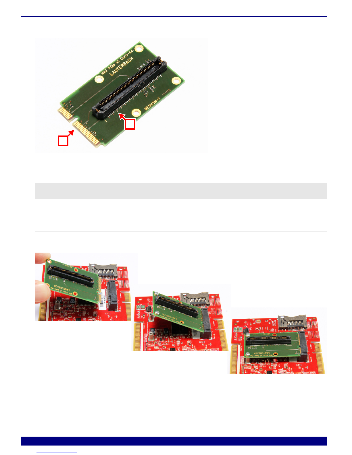
Adapter for Mini-PCIe (LA-3526)
The passive adapter card is used to adapt PC-like targets with trace data coming via MiniPCIe connectors.
Insert the adapter carefully.
Connector Function
AMiniPCIe edge connector
BPowerTrace Serial connector for Serial Port 1
A
B
PowerTrace Serial User´s Guide 1 2
©1989-2018 Lauterbach GmbH
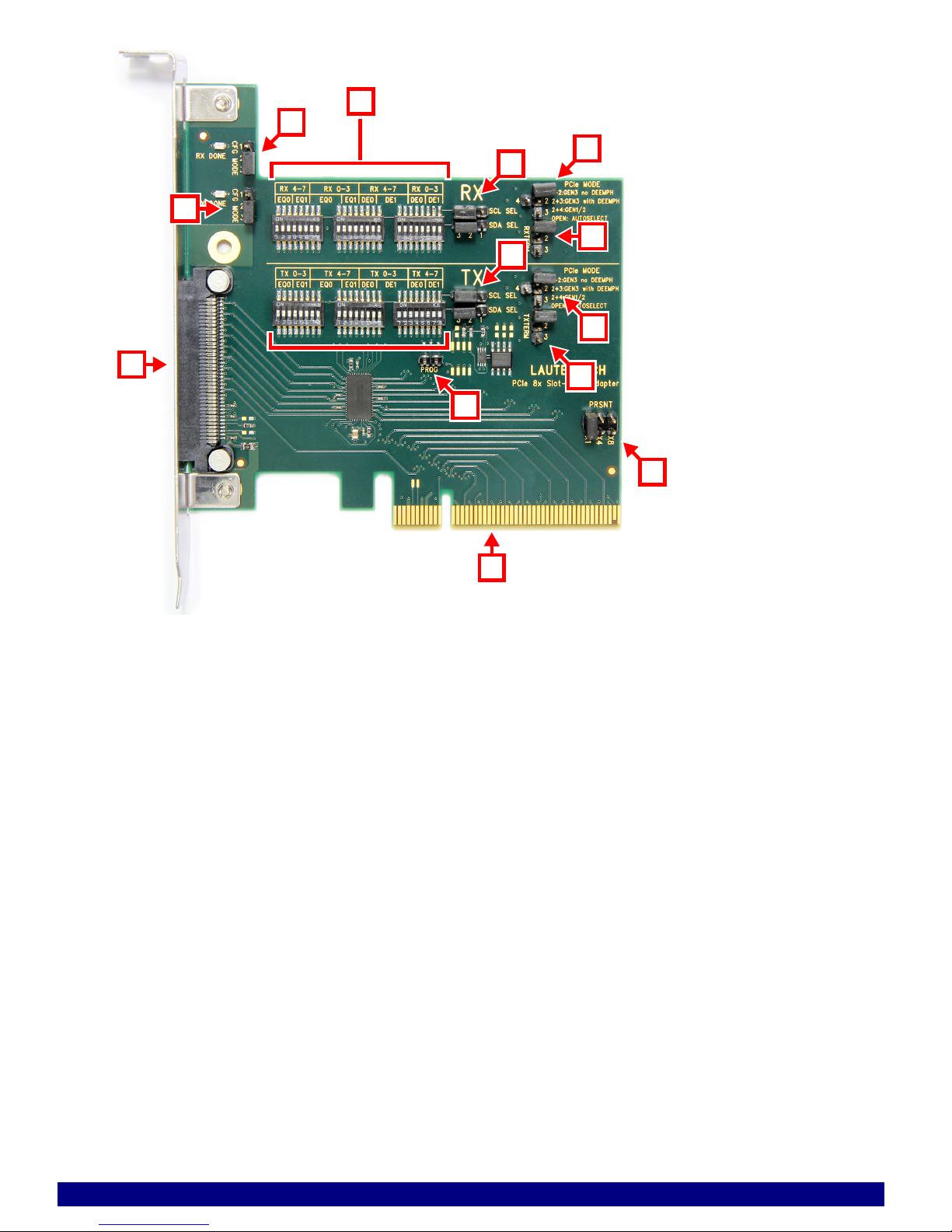
Adapter for PCIe Slot Card (LA-3525)
The active adapter card is used to adapt PC-like targets with trace data coming via PCIe. A special analog
repeater component amplifies the electrical signal and improves the data eye. The component is transparent
to target and tool. It can work in automatic configuration mode or manual configuration mode for
PCIe Gen1,2 and 3.
The form factor follows the standard for PC slot-in cards. The card can be plugged into standard 16-lane-
slots, 8-lane-slots and in case of special open-frame connectors also into 4-lane-slots and 1-lane-slots. If
necessary the metal plate can be removed.
The adapter will be shipped in auto-configuration-mode which will work for most
of the targets. Configuration changes (e.g. deemphasis) should be done
carefully and knowledge of high-speed signaling techniques is necessary.
PowerTrace Serial User´s Guide 1 3
©1989-2018 Lauterbach GmbH
APowerTrace Serial tool connector
BSelector for adapter configuration mode for RX path
CSelector for adapter configuration mode for TX path
DConfiguration switches for equalizer and deemphasis for groups of lanes (RX and TX)
ESelector for adapter configuration mode for RX path
FSelector for protocol specific behavior for RX path
GSelector for termination style for RX path
HSelector for adapter configuration mode for TX path
JSelector for protocol specific behavior for RX path
KSelector for termination style for TX path
LSelector for EEPROM configuration
MPCIe-device-present
OTarget connector
A
B
F
K
J
M
D
E
H
L
O
G
C
PowerTrace Serial User´s Guide 1 4
©1989-2018 Lauterbach GmbH
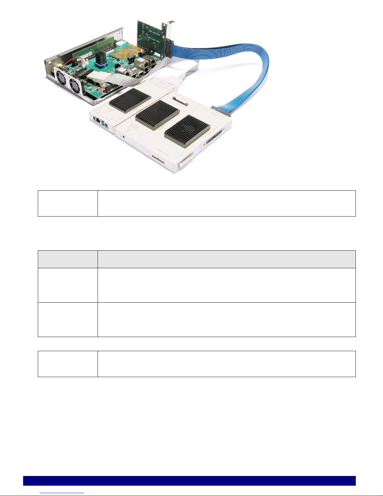
A target setup could look like this:
NOTE: It could be necessary to give mechanical support to the 80pin cable on its way
from tool to target.
LED Function
RX DONE On: RX register configuration done
Off: RX register configuration in progress, failed or target not powered
TX DONE On: TX register configuration done
Off: TX register configuration in progress, failed or target not powered
NOTE: The adapter configuration of RX buffers and TX buffers is pipelined. The TX
configuration can only succeed if RX configuration was successful.

PowerTrace Serial User´s Guide 1 5
©1989-2018 Lauterbach GmbH
CFG Jumper Function
RX CFG
MODE
Must be set to 2-3
Set 1-2: SMB slave mode
Set 2-3: Pin mode
Open: SMB master mode (PROM mode)
TX CFG
MODE
Must be set to 2-3
Set 1-2: SMB slave mode
Set 2-3: Pin mode
Open: SMB master mode (PROM mode)
PROG Must be open
Set: PROM programming mode
Open: normal mode
PRSNT
Jumper
Function
PRSNT Set number of lanes regarding to the PCIe standard. The target OS sometimes
needs this information to configure the PCIe root complex correctly. Don’t leave
the jumper open. Select the next higher number of your lane count, e.g. x4 in
case of 2 lanes.
Set x1: select 1 lane
Set x4: select 4 lanes
Set x8: select 8 lanes
RX Jumper Function
SCL SEL Must be set to 2-3.
Set 1-2: SMB mode
Set 2-3: Pin mode
SDA SEL Must be set to 2-3.
Set 1-2: SMB mode
Set 2-3: Pin mode

PowerTrace Serial User´s Guide 1 6
©1989-2018 Lauterbach GmbH
RXTERM Termination behavior during signal detection.
Default: Open.
Open: unlimited cyclic RX test, Hi-Z during test then 50
Set 1-2: limited cyclic RX test, Hi-Z during test then 50
Set 2-3: manual test with 50termination
PCIe MODE Emphasis/deemphasis configuration
Default: Open
Set 1-2: PCIe Gen3 without Deemphasis
Set 2-3: PCIe Gen3 with Deemphasis
Set 2-4: PCIe Gen1+2
Open: Auto detection of driver parameter
TX Jumper Function
SCL SEL Must be set to 2-3.
Set 1-2: SMB mode
Set 2-3: Pin mode
SDA SEL Must be set to 2-3.
Set 1-2: SMB mode
Set 2-3: Pin mode
TXTERM Termination behavior during signal detection.
Default: Open.
Open: unlimited cyclic RX test, Hi-Z during test then 50
Set 1-2: limited cyclic RX test, Hi-Z during test then 50
Set 2-3: manual test with 50termination
PCIe MODE Emphasis/deemphasis configuration
Default: Open
Set 1-2: PCIe Gen3 without deemphasis
Set 2-3: PCIe Gen3 with deemphasis
Set 2-4: PCIe Gen1+2
Open: Auto detection of driver parameter
RX Jumper Function
PowerTrace Serial User´s Guide 1 7
©1989-2018 Lauterbach GmbH
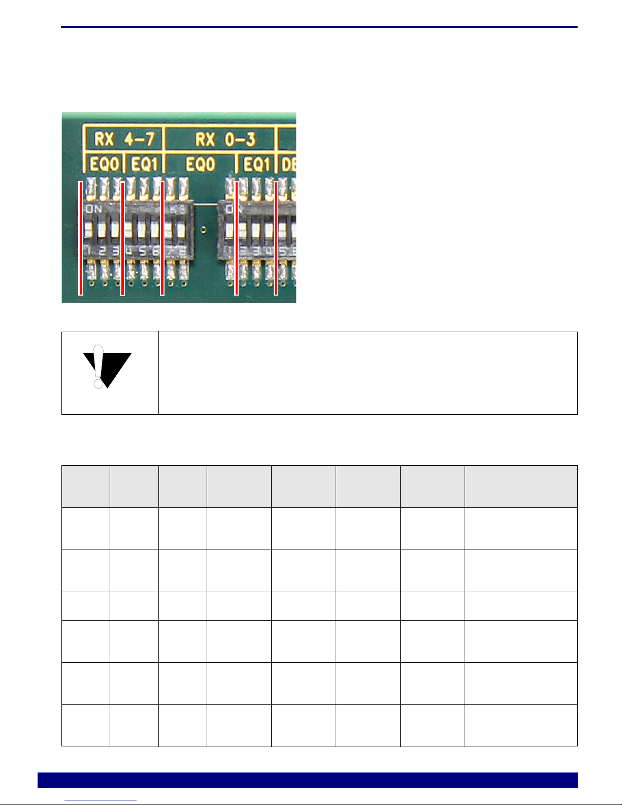
Configuration Switches
Equalization and Deemphasis can be configured separately for RX lane [0-3] and RX lane [4-7] and
TX lane [0-3] and TX lane [4-7]. The configuration switches are grouped and can be set to on (1) and off (0).
Three switches form a mutual group, e.g. switch[1..3]=> parameter EQ0. Within a group only one switch
must be on.
Driver settings for RX and TX will match in most cases.
#EQ0 EQ1 dB at
1.5GHz
dB at
2.5GHz
dB at
4GHz
dB at
6GHz
Suggested for
1100 100 2.5 3.5 3.8 3.1 FR4 and less than
5inch traces
2010 100 3.8 5.4 6.7 6.7 FR4 5-10inch
traces
3000 100 5.0 7.0 8.4 8.4 FR4 10inch traces
4001 100 5.9 8.0 9.3 9.1 FR4 15-20inch
traces
5100 010 7.4 10.3 12.8 13.7 FR4 20-30inch
traces
6010 010 6.9 10.2 13.9 16.2 FR4 25-30inch
traces

PowerTrace Serial User´s Guide 1 8
©1989-2018 Lauterbach GmbH
7000 010 9.0 12.4 15.3 15.9 FR4 25-30inch
traces
8001 010 10.2 13.8 16.7 17.0 8m cable, 30AWG
9100 000 8.5 12.6 17.5 20.7 more than 8m
cables
10 010 000 11.7 16.2 20.3 21.8
11 000 000 13.2 18.3 22.8 23.6
12 001 000 14.4 19.8 24.2 24.7
13 100 001 14.4 20.5 26.4 28.0
14 010 001 16.0 22.2 27.8 29.2
15 000 001 17.6 24.4 30.2 30.9
16 001 001 18.7 25.8 31.6 31.9
else else Not allowed
Equalizer configuration #1 is default.
#DE0 DE1 Vp-p DEM dB internal
Vp-p
Suggested for
1100 100 0.8 0 0.8 FR4 and less than 5inch 4mil
traces
2010 100 0.9 0 0.9 FR4 and less than 5inch 4mil
traces
3000 100 0.9 -3.5 0.6 FR4 and 10inch 4mil traces
#EQ0 EQ1 dB at
1.5GHz
dB at
2.5GHz
dB at
4GHz
dB at
6GHz
Suggested for

PowerTrace Serial User´s Guide 1 9
©1989-2018 Lauterbach GmbH
4001 100 1.0 0 1.0 FR4 and less than 5inch 4mil
traces
5100 010 1.0 -3.5 0.7 FR4 and 10inch 4mil traces
6010 010 1.0 -6 0.5 FR4 and 15inch 4mil traces
7000 010 1.1 0 1.1 FR4 and less than 5inch 4mil
traces
8001 010 1.1 -3.5 0.7 FR4 and 10inch 4mil traces
9100 000 1.1 -6 0.6 FR4 and 15inch 4mil traces
10 010 000 1.2 0 1.2 FR4 and less than 5inch 4mil
traces
11 000 000 1.2 -3.5 0.8 FR4 and 10inch 4mil traces
12 001 000 1.2 -6 0.6 FR4 and 15inch 4mil traces
13 100 001 1.3 0 1.3 FR4 and less than 5inch 4mil
traces
14 010 001 1.3 -3.5 0.9 FR4 and 10inch 4mil traces
15 000 001 1.3 -6 0.7 FR4 and 15inch 4mil traces
16 001 001 1.3 -9 0.5 FR4 and 20inch 4mil traces
else else Not allowed
Deemphasis configuration #1 is default.
#DE0 DE1 Vp-p DEM dB internal
Vp-p
Suggested for

PowerTrace Serial User´s Guide 2 0
©1989-2018 Lauterbach GmbH
Configuration Guide
Target specific adapter configuration might be necessary, if
• it is not possible to get a PCIe link
• the lane speed is below the maximum possible
• the PCIe error rate is high => high bandwidth reduction
Start with the first configuration (#1) and increase step by step (#2 => #3 ...). To verify the configuration the
data eye scanner should be used (Analyzer.ShowFocusEye).
Always first disable the switches before you enable the next configuration. Don’t
have more than one switch enabled within a group. Changing the configuration
must be done like this:
100 : current configuration
000 : set temporary configuration
001 : set final configuration
Table of contents
Other Lauterbach Computer Accessories manuals

Lauterbach
Lauterbach TRACE32 User manual

Lauterbach
Lauterbach AVR8 User manual

Lauterbach
Lauterbach STM8 User manual

Lauterbach
Lauterbach C6000 User manual

Lauterbach
Lauterbach TRACE32 User manual

Lauterbach
Lauterbach XC800 User manual

Lauterbach
Lauterbach MMDSP User manual

Lauterbach
Lauterbach MicroBlaze Debugger User manual

Lauterbach
Lauterbach TRACE 32 Original operating instructions

Lauterbach
Lauterbach TRACE32-ICD User manual


