manuals.online logo
Brands
  1. Home
  2. •
  3. Brands
  4. •
  5. LEGRAND
  6. •
  7. Accessories
  8. •
  9. LEGRAND 3750 00 User manual

LEGRAND 3750 00 User manual

• Manuel d’installation pour interface de commande audio
• Installation manual for audio control interface
• Manual de instalación para central de audio
3750 00
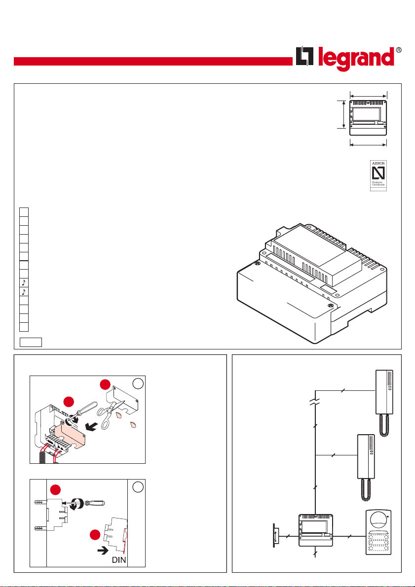
• Installation • Installation• Instalación • Schéma unifilaire 1 porte d'entrée
• Single-wire diagram for 1 entry door
• Esquema unifilar 1 puerta de acceso
230 V ca / 230 V AC / 230 Vac
25+n
5
4+(n-1)
5
4+n
2
• Couper le "passe-fil" et
fermer le couvercle de
connexion de
l'alimentation.
• Cut the "grommet" and
close the cover of the
power supply connection.
• Corte el pasacables y
cierre la tapa de
conexionado de la central.
1
1
2
2
B
A
• Fixation sur le mur ou
rail DIN.
• Wall or DIN rail
mounting.
• Fijación sobre la pared
o carril DIN.
Central
Audio
2628 / 0
• Description
Interfacedecommandeaudiopourportier
électronique (installation conventionnelle
4+n) avec platines de surface Série 7.
Types d'appel:
Appel vibreur
Appel électronique 3 tonalités ou appel
électronique 1 tonalité (au choix sur le
pont de configuration des bornes).
Montage sur rail DIN (7 modules) ou
en surface avec couvercles de
protection des terminaux.
Alimentation 230V / 50-60Hz
Confirmation d'appel sur poste extérieur.
Quatre téléphones maximum par point
d'appel.
Protection de surcharge et court-circuit.
• Description
Audio control interface for electronic
door entry kit (conventional 4+n
installation) with Series 7 surface
outdoor units.
Call types:
Vibrator call
3-tone electronic call or 1-tone electronic
call (to be selected on the setting bridge
of the terminals).
DIN rail (7 modules) or surface mounting
with terminals protection covers.
230V / 50-60Hz power supply
Call confirmation on outdoor station.
Four telephone sets maximum per
calling spot.
Overload and short-circuit protection.
• Descripción
Central de audio para portero
electrónico en instalaciones de sistema
convencional (instalación 4+n) con
placas de superficie Serie 7.
Tipos de llamada:
Llamada zumbador.
Llamada electrónica tritonal ó llamada
electrónica monotonal (seleccionable
mediante puente de configuración en
bornas).
Montaje sobre carril DIN, 7 módulos, ó
en superficie con tapa de protección
de terminales.
Alimentación 230V/50-60Hz.
Confirmación de llamada en placa de
calle.
Máximo de 4 teléfonos por punto de
llamada.
Protegido contra sobrecarga y
cortocircuitos.
88
123
DIN (7 modules)
DIN (7 modules)
DIN (7 mód)
Central
Audio
• Description des bornes • Description of terminals• Descripción de bornas
X
Commande de gâche à courant alternatif / Door release control alternative / Alterna abrepuertas
Y
Fermeture commande de gâche / Door release control closure / Cierre abrepuertas
A
Masse de la platine / Outdoor unit ground / Masa placa
B
Haut-parleurs de la platine / Outdoor unit loudspeakers / Altavoz placa
C
Microphone de la platine / Outdoor unit microphone / Micrófono placa
D
Alimentation de la platine / Outdoor unit power supply / Alimentación placa
I
Bouton commun pour appel électronique / Common button for electronic call / Común pulsadores llamada electrónica
Z
Bouton commun pour appel vibreur / Common button for vibrator call / Común pulsadores llamada zumbador
Configuration pour appel 3 tonalités - 1 tonalité / Setting for 3-tone - 1-tone call / Configuración llamada tritonal-monotonal
2
Masse du téléphone / Telephone ground / Masa teléfono
3
Commande de gâche du téléphone / Telephone door release control / Abrepuertas teléfono
4
Microphone du téléphone / Telephone microphone / Micrófono teléfono
5
Haut-parleur du téléphone / Telephone loudspeaker / Altavoz teléfono
PRIM.
230 V ca / 230 V AC / 230 Vac.
2
• Schéma d'installation 1 porte d'entrée
• Installation diagram for 1 entry door
• Esquema de instalación 1 puerta de acceso
YX
Central audio
• Pour passer d'un
appel 3 tonalités à un
appel 1 tonalité,
insérer un pont entre
les bornes.
• To change the 3-
tone call to a 1-tone
call, insert a bridge
across the terminals.
• Para cambiar la
llamada tritonal por
monotonal, inserte un
puente entre las
bornas.
P4
P5
P6
P4
A
B
C
D
P6
P5
P1
P3
P2
I
P3
P2
P1
Ref.: 3750 00
A B C D I Z
3 4 5
PRIM
2
230 V Ca
230 V AC
230 Vac
Pn
P1
23 4 5
1E PP
23 4 5
1E PP
T-71E
T-71E
• Sections recommandées 1 porte d'entrée • 1 entry door recommended cross-sections • Secciones recomendadas 1 puerta de acceso
A, D
B+4
2
2
C+5
2, 3
200 m.
50 m. 100 m.
2
2
1
2,5
11,5
0,5
0,25 0,25
0,5
0,25 0,25
0,5
0,25 0,25
0,5
0,25 0,25
I 1 1
0,25 0,5
B 4
C 5
• Important: B+4 et C+5 indiquent qu'il faut utiliser sur tout le circuit la section correspondant à la somme des distances platine-interface de commande et interface de commande-téléphone, c'est-à-dire que s'il y
a 100 mètres entre la platine et l'interface de commande et 100 mètres entre l'interface de commande et les téléphones, il faut utiliser les sections correspondant à 200 mètres, et non celles correspondant à 100
mètres, ceci de la platine à l'interface et de l'interface aux téléphones.
• Important: B+4 and C+5 mean that for the entire circuit you must use the cross-section corresponding to the sum of the outdoor unit-control interface and control interface-telephone set distances, i.e. if you
have 100 meters between the outdoor unit and the control interface and 100 meters between the control interface and the telephone sets, you must use the cross-section for 200 meters, and not for 100 meters, that
from outdoor unit to interface and from interface to telephone sets.
• Importante: "B+4" y "C+5" indican que hay que utilizar, en todo el recorrido, al menos la sección correspondiente a la suma de la distancia entre placa-central y central-teléfono. Es decir, si hay 100 metros entre
la placa y la central, y 100 metros entre la central y los teléfonos, hay que utilizar las secciones correspondientes a 200 metros, no las de 100 metros, tanto de placa a central como de central a los teléfonos.
• Connexions
• Connections
• Conexiones
• Nombre de fils
• Number of wires
• Número de hilos
• Sections minimales (en mm2)
• Minimum cross-sections (in mm2)
• Secciones mínimas (mm2)
n
(logements / dwellings
/ viviendas)
Série / Series / Serie 7
3
• Schéma unifilaire 2 portes d'entrée
• 2 entry door single-wire diagram
• Esquema unifilar 2 puertas de acceso
• Sections recommandées 2 portes d'entrée • 2 entry door recommended cross-sections • Secciones recomendadas 2 puertas de acceso
A, D
B+4
2
2
C+5
2, 3
200 m.
50 m. 100 m.
2
2
1
2,5
11,5
0,5
0,25 0,25
0,5
0,25 0,25
0,5
0,25 0,25
0,5
0,25 0,25
I 1 1
0,25 0,5
B 4
C 5
• Important: B+4 et C+5 indiquent qu'il faut utiliser sur tout le circuit la section minimale correspondant à la somme des distances platine-interface de commande et interface de commande-téléphone, c'est-à-dire
que s'il y a 100 mètres entre la platine et l'interface de commande et 100 mètres entre l'interface de commande et les téléphones, il faut utiliser les sections correspondant à 200 mètres, et non celles correspondant à
100 mètres, ceci de la platine à l'interface et de l'interface aux téléphones.
• Important: B+4 and C+5 mean that for the entire circuit you must use the minimum cross-section corresponding to the sum of the outdoor unit-control interface and control interface-telephone set distances, i.e. if
you have 100 meters between the outdoor unit and the control interface and 100 meters between the control interface and the telephone sets, you must use the cross-section for 200 meters, and not for 100 meters,
that from outdoor unit to interface and from interface to telephone sets.
• Importante: "B+4" y "C+5" indican que hay que utilizar, en todo el recorrido, al menos la sección mínima correspondiente a la suma de la distancia entre placa-central y central-teléfono. Es decir, si hay 100 metros
entre la placa y la central, y 100 metros entre la central y los teléfonos, hay que utilizar las secciones correspondientes a 200 metros, no las de 100 metros, tanto de placa a central como de central a los teléfonos.
230 V ca
230 V AC
230 Vac
2
5
4+(n-1)
5
4+n
2
5+n 5+n
2
E-53
Ref.: 3750 03
Central audio
Ref.: 3750 00 Central audio
Ref.: 3750 00
• Connexions
• Connections
• Conexiones
• Nombre de fils
• Number of wires
• Número de hilos
• Sections minimales (en mm2)
• Minimum cross-sections (in mm2)
• Secciones mínimas (mm2)
n
(logements / dwellings
/ viviendas)
4
• Schéma d'installation 2 portes d'entrée
• Installation diagram for 2 entry doors
• Esquema de instalación 2 puertas de acceso
P4
P5
P4
A
B
C
D
P6
P5
P1
P3
P2
I
P3
P2
P1
Pn 23 4 5
1E PP
T-71E
YX
Central audio
Ref.: 3750 00
A B C D I E
3 4 5
PRIM
2
P6
P1
P3
P2
I
YX
Central audio
Ref.: 3750 00
A B C D I Z
3 4 5
PRIM
2
P7
P8
P9
P4
A
B
C
D
P6
P5
P1
P3
P2
I
P3
P2
P1
YX
Central audio
Ref.: 3750 00
A B C D I Z
3 4 5
PRIM
2
• Important
Configurer le E-53 comme un équipement de changeur
automatique (voir notice technique du E-53).
• Important
Set the E-53 to automatic exchange equipment (refer
to E-53 technical data).
• Importante
Configure el E-53 como equipo cambiador automático
(consulte la información técnica que acompaña al E-53).
Pn1
2 6 10 C 7
29 C1 C2 3A
4A 5A
20A 28A
C3 C4 3B 4B 5B
20B 28B
3 4 5 2017
E-53
Ref.: 3750 03
230 V Ca
230 V AC
230 Vac
230 V Ca
230 V AC
230 Vac
1ère entrée
First door
1er Acceso
Série / Series
/ Serie 7 2ème entrée
Second door
2º Acceso
Série / Series
/ Serie 7

Other LEGRAND Accessories manuals

LEGRAND Wattstopper PW-311-B User manual

LEGRAND

LEGRAND Wattstopper PW-311-B User manual

LEGRAND Wattstopper UT-305-1 User manual

LEGRAND

LEGRAND Wattstopper UT-305-1 User manual

LEGRAND Wattstopper DSW-301-R User manual

LEGRAND

LEGRAND Wattstopper DSW-301-R User manual

LEGRAND Wattstopper RS-250 User manual

LEGRAND

LEGRAND Wattstopper RS-250 User manual

LEGRAND Wattstopper DT-205 User manual

LEGRAND

LEGRAND Wattstopper DT-205 User manual

LEGRAND Valena Life LE-753186 User manual

LEGRAND

LEGRAND Valena Life LE-753186 User manual

LEGRAND 0 672 25 User manual

LEGRAND

LEGRAND 0 672 25 User manual

LEGRAND Wattstopper PW-311 User manual

LEGRAND

LEGRAND Wattstopper PW-311 User manual

LEGRAND DW-103 User manual

LEGRAND

LEGRAND DW-103 User manual

LEGRAND 896 20 User manual

LEGRAND

LEGRAND 896 20 User manual

LEGRAND Dooxie 6 003 78 User manual

LEGRAND

LEGRAND Dooxie 6 003 78 User manual

LEGRAND Wattstopper FSP-212 User manual

LEGRAND

LEGRAND Wattstopper FSP-212 User manual

LEGRAND Wattstopper RH-250 Operating and installation instructions

LEGRAND

LEGRAND Wattstopper RH-250 Operating and installation instructions

LEGRAND Wattstopper LMDL-600 User manual

LEGRAND

LEGRAND Wattstopper LMDL-600 User manual

LEGRAND WattStopper DW-100-24-LA User manual

LEGRAND

LEGRAND WattStopper DW-100-24-LA User manual

LEGRAND Watt Stopper DT-305 User manual

LEGRAND

LEGRAND Watt Stopper DT-305 User manual

LEGRAND DT-300 User manual

LEGRAND

LEGRAND DT-300 User manual

LEGRAND 882 07 User manual

LEGRAND

LEGRAND 882 07 User manual

LEGRAND Wattstopper EW-200-120 User manual

LEGRAND

LEGRAND Wattstopper EW-200-120 User manual

LEGRAND Wattstopper PARTITION-SENSOR User manual

LEGRAND

LEGRAND Wattstopper PARTITION-SENSOR User manual

LEGRAND 0 648 40 User manual

LEGRAND

LEGRAND 0 648 40 User manual

LEGRAND 0 546 00 User manual

LEGRAND

LEGRAND 0 546 00 User manual

LEGRAND adorne WNAR153 User manual

LEGRAND

LEGRAND adorne WNAR153 User manual

LEGRAND Wattstopper DT-200 User manual

LEGRAND

LEGRAND Wattstopper DT-200 User manual

Popular Accessories manuals by other brands

Antelope Zen Tour Synergy Core user manual

Antelope

Antelope Zen Tour Synergy Core user manual

Tascam US-122 installation instructions

Tascam

Tascam US-122 installation instructions

Knightsbridge IP9000R Installation & maintenance manual

Knightsbridge

Knightsbridge IP9000R Installation & maintenance manual

Mobotix MX-Proximity-Box Quick install

Mobotix

Mobotix MX-Proximity-Box Quick install

PCB Piezotronics ICP 137B21B Installation and operating manual

PCB Piezotronics

PCB Piezotronics ICP 137B21B Installation and operating manual

Baumer UNAM 12N1914/S14D operating instructions

Baumer

Baumer UNAM 12N1914/S14D operating instructions

Siko MSA510 Translation of the original installation instructions

Siko

Siko MSA510 Translation of the original installation instructions

Hyper Pearl user manual

Hyper

Hyper Pearl user manual

Hytronik HIM34 quick start guide

Hytronik

Hytronik HIM34 quick start guide

Waterpik Technologies WP-480 manual

Waterpik Technologies

Waterpik Technologies WP-480 manual

Alula RE118 install guide

Alula

Alula RE118 install guide

Philips HF3650 quick start guide

Philips

Philips HF3650 quick start guide

AirPatrol Lite RoomUnit user manual

AirPatrol Lite

AirPatrol Lite RoomUnit user manual

Suez CheckPoint Pharma Owner's operation and maintenance manual

Suez

Suez CheckPoint Pharma Owner's operation and maintenance manual

Tascam iU2 owner's manual

Tascam

Tascam iU2 owner's manual

VOILE Voile Split Kit instructions

VOILE

VOILE Voile Split Kit instructions

SLV VALETO 420040 manual

SLV

SLV VALETO 420040 manual

Intenso XC10000 user manual

Intenso

Intenso XC10000 user manual

manuals.online logo
manuals.online logoBrands
  • About & Mission
  • Contact us
  • Privacy Policy
  • Terms and Conditions

Copyright 2025 Manuals.Online. All Rights Reserved.