manuals.online logo
Brands
  1. Home
  2. •
  3. Brands
  4. •
  5. LEGRAND
  6. •
  7. Security Sensor
  8. •
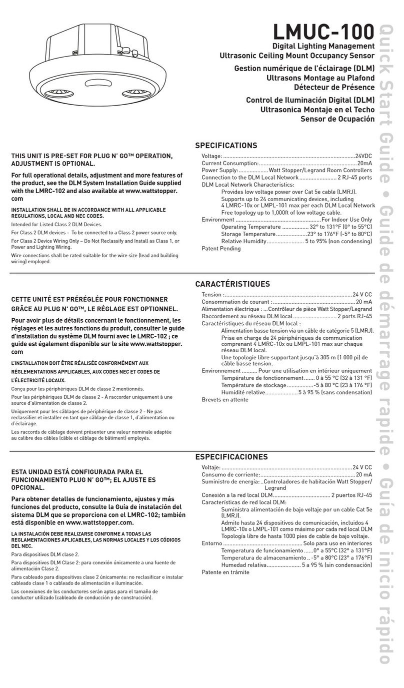
  9. LEGRAND WattStopper LMUC-100-2 User manual

LEGRAND WattStopper LMUC-100-2 User manual

This manual suits for next models

2

Other LEGRAND Security Sensor manuals

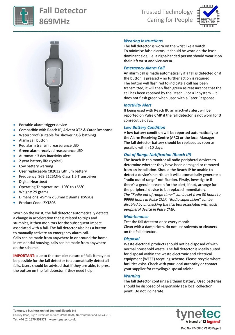
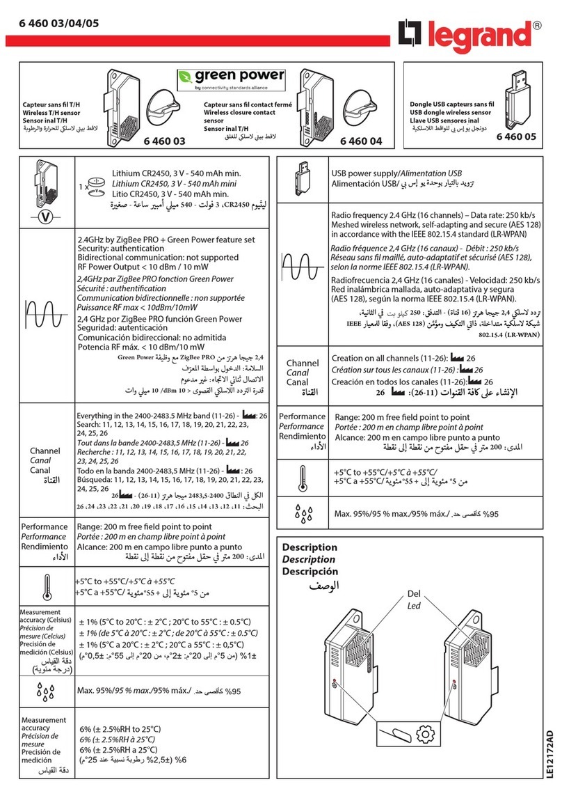
LEGRAND Tynetec ZXT805 User manual

LEGRAND

LEGRAND Tynetec ZXT805 User manual

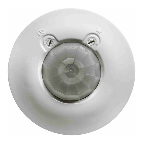
LEGRAND Tynetec Aidcall ZXT491 User manual

LEGRAND

LEGRAND Tynetec Aidcall ZXT491 User manual

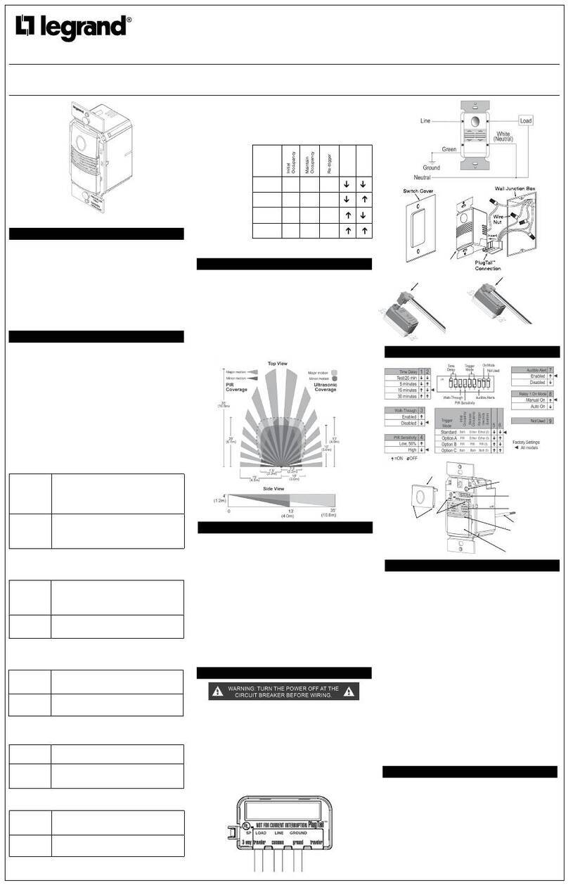
LEGRAND CP Electronics EBDRC-DD User manual

LEGRAND

LEGRAND CP Electronics EBDRC-DD User manual

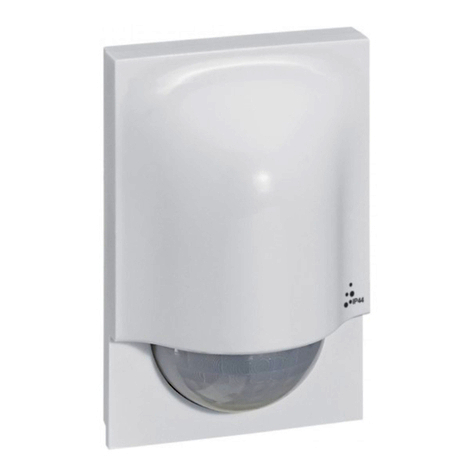
LEGRAND 088230 User manual

LEGRAND

LEGRAND 088230 User manual

LEGRAND CP Electronics MWS3A-AT-DD User manual

LEGRAND

LEGRAND CP Electronics MWS3A-AT-DD User manual

LEGRAND tynetec ZXT815 User manual

LEGRAND

LEGRAND tynetec ZXT815 User manual

LEGRAND Mosaic 493 31 User manual

LEGRAND

LEGRAND Mosaic 493 31 User manual

LEGRAND CP Electronics EBDHS-AT-PRM User manual

LEGRAND

LEGRAND CP Electronics EBDHS-AT-PRM User manual

LEGRAND CP Electronics Casambi EBDMR-CB-DD User manual

LEGRAND

LEGRAND CP Electronics Casambi EBDMR-CB-DD User manual

LEGRAND Mallia Senses with Netatmo 2 815 02DS/MB/MW Original operating instructions

LEGRAND

LEGRAND Mallia Senses with Netatmo 2 815 02DS/MB/MW Original operating instructions

LEGRAND CP Electronics MWS3A-AT-AD User manual

LEGRAND

LEGRAND CP Electronics MWS3A-AT-AD User manual

LEGRAND 0 489 18 User manual

LEGRAND

LEGRAND 0 489 18 User manual

LEGRAND 488 30 User manual

LEGRAND

LEGRAND 488 30 User manual

LEGRAND Triscan 488TRI3W User manual

LEGRAND

LEGRAND Triscan 488TRI3W User manual

LEGRAND Celiane Series User manual

LEGRAND

LEGRAND Celiane Series User manual

LEGRAND LE03020AB User manual

LEGRAND

LEGRAND LE03020AB User manual

LEGRAND Wattstopper PW-311-U User manual

LEGRAND

LEGRAND Wattstopper PW-311-U User manual

LEGRAND CP Electronics EBMHS-BLV User manual

LEGRAND

LEGRAND CP Electronics EBMHS-BLV User manual

LEGRAND Wattstopper FDP-301SR User manual

LEGRAND

LEGRAND Wattstopper FDP-301SR User manual

LEGRAND 0 489 53 User manual

LEGRAND

LEGRAND 0 489 53 User manual

LEGRAND 0 490 8 User manual

LEGRAND

LEGRAND 0 490 8 User manual

LEGRAND CP Electronics EBDHS-KNX User manual

LEGRAND

LEGRAND CP Electronics EBDHS-KNX User manual

LEGRAND PIR IP41 Instruction Manual

LEGRAND

LEGRAND PIR IP41 Instruction Manual

LEGRAND Bticino MyHOME 3518MW User manual

LEGRAND

LEGRAND Bticino MyHOME 3518MW User manual

Popular Security Sensor manuals by other brands

Honeywell Home PROSiXCOCN Installation and setup guide

Honeywell Home

Honeywell Home PROSiXCOCN Installation and setup guide

Duevi SIRPZ-RB-868 Operation

Duevi

Duevi SIRPZ-RB-868 Operation

RKI 65-2483RK Operator's manual

RKI

RKI 65-2483RK Operator's manual

Nortech PD160 Enhanced Series user manual

Nortech

Nortech PD160 Enhanced Series user manual

Omron K8AC-H2 manual

Omron

Omron K8AC-H2 manual

Agilent Technologies G8610 Series Quick reference card

Agilent Technologies

Agilent Technologies G8610 Series Quick reference card

Shinko SE2EA-1-0-0 instruction manual

Shinko

Shinko SE2EA-1-0-0 instruction manual

Det-Tronics X Series instructions

Det-Tronics

Det-Tronics X Series instructions

ACR Electronics COBHAM RCL-300A Product support manual

ACR Electronics

ACR Electronics COBHAM RCL-300A Product support manual

TOOLCRAFT 1712612 operating instructions

TOOLCRAFT

TOOLCRAFT 1712612 operating instructions

Elkron IM600 Installation, programming and functions manual

Elkron

Elkron IM600 Installation, programming and functions manual

Bosch WEU PDO 6 Original instructions

Bosch

Bosch WEU PDO 6 Original instructions

THORLABS PDA10JT user guide

THORLABS

THORLABS PDA10JT user guide

Waeco UV-DETECT operating manual

Waeco

Waeco UV-DETECT operating manual

Intermatic IOS-DSIMF manual

Intermatic

Intermatic IOS-DSIMF manual

Siemens AZL66 Series manual

Siemens

Siemens AZL66 Series manual

BTI Profiline Multi Finder operating instructions

BTI

BTI Profiline Multi Finder operating instructions

Challenger SL01 instruction manual

Challenger

Challenger SL01 instruction manual

manuals.online logo
manuals.online logoBrands
  • About & Mission
  • Contact us
  • Privacy Policy
  • Terms and Conditions

Copyright 2025 Manuals.Online. All Rights Reserved.

Quick Start Guide
SENSOR PLACEMENT 10’ MAX. HEIGHT
Strong air
supply
6’
Sensor
Mount sensor at least 6’ away
from strong air supply
31.6’
9.63m
max.
31.6’
9.63m
Line
Voltage
Room
Controller
J-Boxes
Daylight Sensor
SwitchSwitch
Corner Mount
Sensor
Ceiling Mount
Sensor
DLM Local Network
Low Voltage
LMRJ Cables
Loads
2
1
Line/Hot
Black wire
Neutral
White wire
Red wire
to Load A (1)
Yellow wire
to Load B (2)
LMRC
102
LMUC-100-2
Digital Lighting Management
Ultrasonic Ceiling Mount
Occupancy Sensor
COVERAGE PATTERN
The LMUC-100-2 provides a 360° coverage pattern. The
coverage shown represents walking motion at a mounting
height of 8 to 10 feet.
31.6 ft
9.63m
22.3 ft
6.79m
Minor Motion
Major Motion
Room
Controller
J Box
Ceiling Mount
Occupancy
Sensor
Switch
To
Load
Sensor Sensor
30’
9.14m
50’
15.24m
Voltage: ...............................................................................24VDC
Current Consumption:......................................................... 20mA
Power Supply:............. Watt Stopper/Legrand Room Controllers
Connection to the DLM Local Network...................2 RJ-45 ports
DLM Local Network Characteristics:
Provides low voltage power over Cat 5e cable (LMRJ).
Supports up to 24 communicating devices, including 4
LMRC-10x or LMPL-101 max per each DLM Local Network.
Free topology up to 1,000ft of low voltage cable.
Environment ................................................. For Indoor Use Only
Operating Temperature ....................32° to 131°F (0° to 55°C)
Storage Temperature...................... 23° to 176°F (-5° to 80°C)
Relative Humidity...........................5 to 95% (non condensing)
Patent Pending
THIS UNIT IS PRESET FOR PLUG n’ GO™
OPERATION, ADJUSTMENT IS OPTIONAL.
For full operational details, adjustment and more
features of the product, see the DLM System
Installation Guide supplied with the LMRC-102 and
also available at www.wattstopper.com
CONNECTIVITY
The illustrations below show examples of free-topology wiring. The LMUC-100-2
communicates to all other Digital Lighting Management devices connected to the low
voltage DLM Local Network, regardless of their position on the DLM Local Network.
INSTALLATION SHALL BE
IN ACCORDANCE WITH ALL
APPLICABLE REGULATIONS,
LOCAL AND NEC CODES.
Intended for Listed Class
2 DLM Devices.
For Class 2 DLM devices -
To be connected to a Class
2 power source only.
For Class 2 Device Wiring Only –
Do Not Reclassify and Install as
Class 1, or Power and Lighting
Wiring.
Wire connections shall be rated
suitable for the wire size (lead
and building wiring) employed.
6/2009
11438r1
Please
Recycle
2800 De La Cruz Blvd.
Santa Clara, CA 95050
Phone: 800.879.8585
www.wattstopper.com
Ceiling hole
Rear
housing
4" Octagonal J-Box
(at least 1.5" deep)
Front cover
Ceiling
Rear
housing
Front cover
Category 5 cable
Category 5 cable
Spring clips (2)
Screws
To octagon box: Through ceiling tile:
TROUBLESHOOTING
Loads do not operate as expected.
LEDs don’t light, display
is off
1. Check to see that the the sensor is connected to the DLM local Network.
2. Check for 24VDC input to the sensor: Plug in a different DLM device at the sensor location.
If the device does not power up, 24VDC is not present.
• Check the high voltage connections to the room controller.
• If high voltage connections are good and high voltage is present, recheck DLM local
Network connections between the sensor and the room controller.
The wrong lights are
controlled
1. Configure the sensor to control the desired lights using the Push n’ Learn adjustment
procedure.
LEDs turn ON and OFF but
load doesn’t switch
1. Make sure device is not in PnL.
2. Check load connections to room controller.
MOUNTING
FACTORY PRESET OPERATION
Sensor Parameters
T-DELAY Time Delay 20 minutes
Ultrasonic
Sensitivity 70%
W-T Walk Through OFF
Load Parameters
Load 1 Loads 2-8
or more**
Plug Load
ON Mode
Operation* AUTO-ON
MANUAL-ON
if switch is
connected.
AUTO-ON
if no switch.
AUTO-ON
Blink Warning OFF OFF OFF
Daylighting ON OFF OFF
*Auto-OFF is enabled according to the sensor Time Delay when a
sensor is bound to the load, regardless of whether the load was turned
on automatically with occupancy or manually using a switch.
** Max 8 loads using LMRC-100 series room controllers.
WARNING: TO CONNECT A COMPUTER TO THE DLM LOCAL NETWORK USE THE
LMCI100. NEVER CONNECT THE DLM LOCAL NETWORK TO AN ETHERNET PORT
 DOING SO MAY DAMAGE COMPUTERS AND OTHER CONNECTED EQUIPMENT.
WARNING: Do Not Install To Cover a Junction Box Having Class 1, 3 or Power and Lighting Circuits.