manuals.online logo
Brands
  1. Home
  2. •
  3. Brands
  4. •
  5. LEGRAND
  6. •
  7. Switch
  8. •
  9. LEGRAND Pass & Seymour TM8LOCATOR-LA User manual

LEGRAND Pass & Seymour TM8LOCATOR-LA User manual

This manual suits for next models

1

Other LEGRAND Switch manuals

LEGRAND Raritan RSS4-102 Service manual

LEGRAND

LEGRAND Raritan RSS4-102 Service manual

LEGRAND Radiant Series User manual

LEGRAND

LEGRAND Radiant Series User manual

LEGRAND Arteor 5 742 70 User manual

LEGRAND

LEGRAND Arteor 5 742 70 User manual

LEGRAND 4 126 23 User manual

LEGRAND

LEGRAND 4 126 23 User manual

LEGRAND DMX3 User manual

LEGRAND

LEGRAND DMX3 User manual

LEGRAND DPX3 250 User manual

LEGRAND

LEGRAND DPX3 250 User manual

LEGRAND LMSW-605-W User manual

LEGRAND

LEGRAND LMSW-605-W User manual

LEGRAND In One 770 24 User manual

LEGRAND

LEGRAND In One 770 24 User manual

LEGRAND 672 63 User manual

LEGRAND

LEGRAND 672 63 User manual

LEGRAND Wattstopper LMDM-101 User manual

LEGRAND

LEGRAND Wattstopper LMDM-101 User manual

LEGRAND Pro 21 7756 31 User manual

LEGRAND

LEGRAND Pro 21 7756 31 User manual

LEGRAND radiant LC2201 User manual

LEGRAND

LEGRAND radiant LC2201 User manual

LEGRAND 4128 58 User manual

LEGRAND

LEGRAND 4128 58 User manual

LEGRAND 4 130 10 User manual

LEGRAND

LEGRAND 4 130 10 User manual

LEGRAND 3 109 53 User manual

LEGRAND

LEGRAND 3 109 53 User manual

LEGRAND Excel Life EM802TD User manual

LEGRAND

LEGRAND Excel Life EM802TD User manual

LEGRAND 0 883 07 User manual

LEGRAND

LEGRAND 0 883 07 User manual

LEGRAND Plexo User manual

LEGRAND

LEGRAND Plexo User manual

LEGRAND DMX User manual

LEGRAND

LEGRAND DMX User manual

LEGRAND 0 677 55 User manual

LEGRAND

LEGRAND 0 677 55 User manual

LEGRAND 0 676 94 User manual

LEGRAND

LEGRAND 0 676 94 User manual

LEGRAND In One Celiane 672 15 User manual

LEGRAND

LEGRAND In One Celiane 672 15 User manual

LEGRAND HKRL10 User manual

LEGRAND

LEGRAND HKRL10 User manual

LEGRAND Pass & Seymour RRW600U User manual

LEGRAND

LEGRAND Pass & Seymour RRW600U User manual

Popular Switch manuals by other brands

SMC Networks SMC6224M Technical specifications

SMC Networks

SMC Networks SMC6224M Technical specifications

Aeotec ZWA003-S operating manual

Aeotec

Aeotec ZWA003-S operating manual

TRENDnet TK-209i Quick installation guide

TRENDnet

TRENDnet TK-209i Quick installation guide

Planet FGSW-2022VHP user manual

Planet

Planet FGSW-2022VHP user manual

Avocent AutoView 2000  AV2000BC AV2000BC Installer/user guide

Avocent

Avocent AutoView 2000 AV2000BC AV2000BC Installer/user guide

Moxa Technologies PT-7728 Series user manual

Moxa Technologies

Moxa Technologies PT-7728 Series user manual

Intos Electronic inLine 35392I operating instructions

Intos Electronic

Intos Electronic inLine 35392I operating instructions

Cisco Catalyst 3560-X-24T Technical specifications

Cisco

Cisco Catalyst 3560-X-24T Technical specifications

Asante IntraCore IC3648 Specifications

Asante

Asante IntraCore IC3648 Specifications

Siemens SIRIUS 3SE7310-1AE Series Original operating instructions

Siemens

Siemens SIRIUS 3SE7310-1AE Series Original operating instructions

Edge-Core DCS520 quick start guide

Edge-Core

Edge-Core DCS520 quick start guide

RGBLE S00203 user manual

RGBLE

RGBLE S00203 user manual

Thrustmaster FLIGHT SIMULATOR X quick guide

Thrustmaster

Thrustmaster FLIGHT SIMULATOR X quick guide

Southwire SURGE GUARD 41390 RVC troubleshooting guide

Southwire

Southwire SURGE GUARD 41390 RVC troubleshooting guide

Buhler Nivotemp NT 61 Brief instructions

Buhler

Buhler Nivotemp NT 61 Brief instructions

Kramer VS-41HDCP user manual

Kramer

Kramer VS-41HDCP user manual

Techly IDATA AU-270 user manual

Techly

Techly IDATA AU-270 user manual

Belkin F1U109 user manual

Belkin

Belkin F1U109 user manual

manuals.online logo
manuals.online logoBrands
  • About & Mission
  • Contact us
  • Privacy Policy
  • Terms and Conditions

Copyright 2025 Manuals.Online. All Rights Reserved.

LIMITED FIVE YEAR WARRANTY
Pass & Seymour/Legrand will remedy any defect in workmanship or material in Pass & Seymour/Legrand
products which may develop under proper and normal use within five years from the date of purchase by a
consumer:
(1) by repair or replacement, or, at Pass & Seymour/Legrand’s option, (2) by return of an amount equal to the
consumer’s purchase price. Such remedy is IN LIEU OF ANY AND ALL EXPRESSED OR IMPLIED
WARRANTIES OF MERCHANTABILITY OR FITNESS FOR A PARTICULAR PURPOSE. Such remedy by
Pass & Seymour/Legrand does not include or cover cost of labor for removal or reinstallation of the product.
ALL OTHER FURTHER ELEMENTS OF DAMAGE (INCIDENTAL OR CONSEQUENTIAL DAMAGES) FOR
BREACH OF ANY AND ALL EXPRESSED OR IMPLIED WARRANTIES INCLUDING WARRANTIES OF
MERCHANTABILITY OR FITNESS FOR A PARTICULAR PURPOSE ARE EXCLUDED HEREBY. (Some
states do not allow disclaimer or exclusion or limitation of incidental or consequential damages, so the
above disclaimers and limitation or exclusion may not apply to you.) ANY IMPLIED WARRANTIES
INCLUDING WHERE REQUIRED WARRANTIES OF MERCHANTABILITY OR FITNESS FOR A PARTICULAR
PURPOSE SHALL BE LIMITED TO THE FIVE YEAR PERIOD SET FORTH ABOVE. (Some states do not
allow limitation on how long an implied warranty lasts, so the above limitation may not apply to you.)
To ensure safety, all repairs to Pass & Seymour/Legrand products must be made by Pass &
Seymour/Legrand or under its specific direction. Procedure to obtain performance of any warranty
obligation is as follows: (1) Contact Pass & Seymour/Legrand, P.O. Box 4822, Syracuse, NY 13221 for
instructions concerning return or repair; (2) return the product to Pass & Seymour/Legrand, postage paid,
with your name and address and a written description of the installation or use of the Pass &
Seymour/Legrand product, and the observed defects or failure to operate, or other claimed basis for
dissatisfaction.
This warranty gives you specific legal rights and you may also have other rights which vary from state to state.
WIRING AND INSTALLATION DIAGRAMS BELOW
To be installed by a ertified ele tri ian or other qualified person.
WARNING – To prevent severe shock or electrocution, always turn power OFF
at the service panel before installing this unit, working on the circuit,
or changing a lamp.
CAUTION – For permanently installed incandescent lights only. To reduce the
risk of overheating and possible damage to other equipment, do not install the
Home Locator to control a receptacle, a fluorescent light or compact fluorescent
light bulb, a motor-operated appliance, a transformer supplied appliance, photo-
cell or motion detector based lighting.
Do not use the Home Locator with incandescent lamps whose power require-
ment exceeds maximum power (stated in watts) of the Home Locator.
Do not connect the Home Locator to a power source other than 120VAC, 60Hz only.
A 25W minimum power load is required.
DIRECTIONS:
1. Disconnect power to the circuit by removing the fuse or turn the circuit
breakers OFF before installing.
2. Remove the wall plate and switch mounting screws, pull the existing switch
from the wall box.
NOTE: Prior to installation, the Air Gap switch should be in the OFF position
(Down), to disconnect the switch circuit from the power source (see Locator
Functions).
3. Connect the Home Locator as shown in the installation and wiring diagrams,
using the enclosed wire nuts. Device uses 18 gauge wire (see Table 1 for wire
ranges). Install the Home Locator in the wall box, with the word “TOP” on the
metal strap right side up, using the mounting screws provided.
4. Replace the wall plate; restore the power connection to switch. Then slide the
Air Gap switch to the ON position (Up). The green indicator should glow.
OPERATION INSTRUCTIONS: (refer to Locator Functions)
1. Press the top of the paddle to turn exterior house light on. Press the bottom
of the paddle to turn exterior house light off.
(Red indicator glows when the exterior house light is ON, green indicator glows
when the exterior house light is OFF.)
2. Press the button to activate the home locate mode (light flashes per S.O.S.
code); press again to turn off. (Red indicator also flashes with S.O.S. code.)
NOTE: In an emergency, first call your local emergency services hotline (in many
areas 911) and give them all requested information including your home address.
Instruct them to look for the flashing exterior house light.
CAUTION:
1. Always slide the Air Gap switch in the full down (OFF) position when changing
a light bulb.
2. Either LED illumination indicates a working exterior house light. Should the
LED illumination be absent, check the light bulb. It may be burned out or loose
in the socket.
NOTE: For optimum use as an emergency lighting device, the home locator
should be used on an outside house or porch light, easily visible from your street.
Use only copper or copper clad wire with this device.
This device complies with Part 15 of the FCC Rules. Operation is subject to the
following two conditions: (1) This device may not cause harmful interference, and
(2) this device must accept any interference received, including interference that
may cause undesired operation.
This Class B digital apparatus complies with Canadian ICES-003.
Table 1
READ AND SAVE THESE INSTRUCTIONS!
INSTRUCCIONES EN ESPAÑOL
LE A Y G U A R D E E S T A S I N S T R U C C I O N E S
Installation DiagramWiring Diagram
Lo ator Fun tions
AIR GAP SWITCH
LED ILLUMINATION
PRESS HERE FOR
HOME LOCATE FUNCTION
HOME
LOCATOR
S ngle Pole 500 Watt 120VAC 60Hz
LOCALIZADOR
PARA LA CASA
Un polar 500 Watts 120 VCA 60 Hz
PRESS HERE
TO TURN ON
PRESS HERE
TO TURN OFF
WIRE CONNECTOR USAGE CHART
WIRE COMBINATIONS STRIP LENGTHS COLOR
1#14 & 1#16; 1#14 & 2#18; 2, 3#16; #14 – 1/2", #16 & #18 – 9/16" ORANGE
1#16 & 1 – 3#18; 3 – 5#18; 2#18
1#14 & 1, 2#16; 1#14 & 1, 2#18; #14 & #16 – 7/16", #18 – 1/2" IVORY
2, 3#16; 2 – 5#18
LOS DIAGRAMAS DE CABLEADO E INSTALACIÓN SE PRESENTAN ABAJO
Para ser instalado por un ele tri ista ertifi ado o persona ompetente.
ADVERTENCIA – Para evitar serios electrochoques o electrocución, siempre
apague el suministro eléctrico en el panel de servicio antes de instalar esta
unidad, trabajar en el circuito o cambiar una bombilla.
PRECAUCIÓN – Para luces incandescentes instaladas de manera permanente
únicamente. Para reducir el riesgo de recalentamiento y los posibles daños a
otros equipos, no instale el Localizador para la casa para controlar un
receptáculo, una luz o tubo fluorescente, un electrodoméstico a motor, un
electrodoméstico equipado con transformador, una luz controlada por célula
fotoeléctrica o por detector de movimiento.
No use el Localizador para la casa con lámparas incandescentes cuyo consumo
máximo exceda la potencia máxima (indicada en watts) del Localizador para la
casa.
Conecte el Localizador para la casa únicamente a una fuente eléctrica de 120
VCA, 60 Hz.
Requiere una carga mínima de 25 W.
INSTRUCCIONES:
1. Antes de instalar, desconecte el suministro eléctrico al circuito, quite el fusible
o apague los disyuntores (OFF).
2. Retire la placa de pared y los tornillos de montaje del interruptor y retire el
interruptor existente de la caja de pared.
NOTA: Antes de proceder con la instalación, el microinterruptor debe estar
apagado (en la posición OFF, hacia abajo). Para desconectar el circuito del
interruptor, consulte Funciones del Localizador.
3. Conecte el Localizador para la casa con los capuchones para alambres
suministrados, tal como se muestra en los diagramas de cableado e
instalación. El dispositivo utiliza alambres calibre 18 (consulte la Tabla 1 para
determinar el calibre de los alambres). Instale el Localizador para la casa en la
caja de pared con los tornillos de montaje suministrados y con la palabra
“TOP” impresa en la banda metálica hacia arriba.
4. Vuelva a colocar la placa de pared y restaure el suministro eléctrico al
interruptor. Deslice el microinterruptor a la posición ON (encendido, arriba). El
indicador verde se ilumina.
INSTRUCCIONES DE OPERACIÓN: (Consulte Funciones del Localizador.)
1. Presione la parte superior de la paleta para encender la luz exterior de la casa.
Presione la parte inferior de la paleta para apagar la luz exterior de la casa.
(El indicador rojo se ilumina cuando la luz exterior de la casa está encendida. El
indicador verde se ilumina cuando la luz exterior de la casa está apagada.)
2. Presione el botón para activar la modalidad de localización para la casa (la luz
destella “S.O.S.” en código Morse). Oprima nuevamente para apagarla. (El
indicador rojo también destella “S.O.S.” en código Morse.)
NOTA: En una emergencia, llame primero a la línea telefónica directa de servicios
de emergencia local (911 en muchas áreas) y proporcione toda la información
solicitada, incluso la dirección de su casa. Indique que deben buscar la casa
cuya luz exterior destella intermitentemente.
PRECAUCIÓN:
1. Siempre deslice el microinterruptor completamente hacia abajo (OFF,
apagado) cuando cambie una bombilla.
2. Tanto una como otra iluminación de LED indica que la luz exterior funciona.
En caso de estar apagada, inspeccione la bombilla que puede estar floja o
quemada.
Alambre a la fuente
(Negro)
Alambre
ala lámpara
(Negro)
ALAMBRE DE
PUESTA A TIERRA
(Verde o Desnudo)
Girar
Diagrama de instala iónDiagrama de ableado
2. Appuyer sur le bouton pour activer le mode de localisation de la maison (la
lumière clignote selon le code Morse « S.O.S. ») ; appuyer à nouveau pour
arrêter. (L’indicateur lumineux rouge clignote aussi selon le code « S.O.S. »)
REMARQUE : En cas d’urgence, appeler immédiatement les services de
secours locaux (en général en composant le 911) et donner toute l’information
demandée, y compris votre adresse. Précisez-leur de chercher la maison dont la
lumière extérieure clignote.
MISE EN GARDE :
1. Toujours placer le micro-interrupteur en position basse (OFF/ARRÊT) avant de
changer une ampoule.
2. Le fait que la DEL rouge ou verte soit allumée indique que la lumière extérieure
fonctionne correctement. Si aucune DEL n’est allumée, vérifier l’ampoule. Elle
peut être grillée ou mal vissée dans son support.
REMARQUE : Pour assurer une efficacité optimale en cas d’urgence, le
Localisateur de maison doit contrôler une lampe extérieure (porche, etc.)
facilement visible de la rue.
N’utiliser ce dispositif qu’avec des fils en cuivre ou cuivrés.
Ce dispositif est conforme à la section 15 des Règles du FCC. Son utilisation est
sujette aux deux conditions suivantes : (1) Ce dispositif ne doit pas causer
d’interférence nuisible, et (2) ce dispositif doit accepter toutes les interférences
reçues, y compris les interférences qui peuvent causer un fonctionnement
indésirable.
Cet appareil numérique de la classe B est conforme à la norme NMB-003 du
Canada.
Tableau 1
GARANTIE LIMITÉE DE CINQ ANS
Pass & Seymour/Legrand remédiera à tout vice de matière ou d’exécution susceptible de se présenter dans les
produits Pass & Seymour/Legrand dans le cadre de leur utilisation correcte et normale pendant une période de cinq
ans à compter de leur date d’achat par un consommateur en procédant : (1) à leur réparation ou remplacement, ou au
gré de Pass & Seymour/Legrand, (2) au remboursement d’un montant égal au prix d’achat payé par le consommateur.
Ledit remède tient LIEU ET PLACE DE TOUTES GARANTIES EXPRESSES OU TACITES DE QUALITÉ MARCHANDE
OU DE CONVENANCE À UN USAGE PARTICULIER. Ledit remède offert par Pass & Seymour/Legrand ne comprend ni
ne couvre les frais de main-d’œuvre nécessaires au démontage ou à la réinstallation du produit. TOUS LES AUTRES
ÉLÉMENTS DE DOMMAGES (DOMMAGES ACCESSOIRES OU INDIRECTS) POUR VIOLATION DE TOUTES
GARANTIES EXPRESSES OU TACITES, Y COMPRIS LES GARANTIES DE QUALITÉ MARCHANDE OU DE
CONVENANCE À UN USAGE PARTICULIER, SONT PAR LA PRÉSENTE EXCLUS. (Certaines provinces n’autorisent
pas de stipulations d’exonération, d’exclusion ou de limitation des dommages accessoires ou indirects; par
conséquent, la stipulation d’exonération, d’exclusion ou de limitation susmentionnée peut ne pas s’appliquer à votre
cas.) TOUTES GARANTIES TACITES, Y COMPRIS, SELON LE CAS, LES GARANTIES DE QUALITÉ MARCHANDE ET
DE CONVENANCE À UN USAGE PARTICULIER, SERONT LIMITÉES À LA PÉRIODE DE CINQ ANS STIPULÉE CI-
DESSUS. (Certaines provinces n’autorisent pas de limitations sur la durée d’une garantie tacite; par conséquent, la
limitation susmentionnée peut ne pas s’appliquer à votre cas.)
Pour assurer la sécurité, toutes les réparations des produits Pass & Seymour/Legrand doivent être effectuées par Pass
& Seymour/Legrand, ou sous son contrôle direct. La procédure pour obtenir exécution de toute obligation au titre de la
garantie est la suivante : (1) contactez Pass & Seymour/Legrand, P.O. Box 4822, Syracuse, NY 13221, pour recevoir
les instructions concernant tout renvoi ou réparation; (2) renvoyez le produit à Pass & Seymour/Legrand, port payé, en
indiquant vos nom et adresse et en joignant une description par écrit de l’installation ou de l’usage du produit Pass &
Seymour/Legrand ainsi que de la défaillance ou des défauts constatés, ou de toute autre base d’insatisfaction
avancée.
La présente garantie vous donne des droits juridiques spécifiques et il se peut que vous ayez également d’autres
droits qui peuvent varier d’une province à l’autre.
NOTA: Para optimizar su uso como dispositivo de iluminación de emergencia, el
Localizador para casa debe usarse en una luz exterior o del porche de la casa
que sea fácilmente visible desde la calle.
S lo utilice alambre de cobre o cobrizado con este dispositivo.
Este dispositivo cumple con la Parte 15 de las Reglamentaciones de la FCC. Su
uso está sujeto a las dos condiciones siguientes: (1) Este dispositivo no causa
interferencia dañina y (2) este dispositivo debe aceptar cualquier interferencia
que reciba, incluso aquellas que puedan causar un funcionamiento no deseado.
Este aparato digital Clase B cumple con las reglamentaciones canadienses
ICES-003.
Tabla 1
GARANTÍA LIMITADA DE CINCO AÑOS
Pass & Seymour/Legrand remediará cualquier defecto de mano de obra o materiales en los productos Pass &
Seymour/Legrand que pudiese ocurrir bajo uso correcto y normal y correcto durante cinco años desde la fecha de
compra por el consumidor. (1) mediante reparación o reemplazo o, a opción de Pass & Seymour/Legrand, (2)
devolviendo un monto igual a el precio de compra pagado por el consumidor. Dicho recurso es EN LUGAR DE
CUALQUIERA Y TODAS LAS GARANTÍAS EXPRESAS O IMPLÍCITAS DE COMERCIABILIDAD O ADECUACIÓN CON
UN FIN EN PARTICULAR. Dicho recurso por parte de Pass & Seymour no incluye ni cubre el costo de mano de obra
para retirar o reinstalar el producto. POR LA PRESENTE SE EXCLUYE CUALQUIER OTRO ELEMENTO DE DAÑO
(INCIDENTAL O INDIRECTO) POR INCUMPLIMIENTO DE CUALQUIER GARANTÍA EXPRESA O IMPLÍCITA, INCLUSO
GARANTÍAS DE COMERCIABILIDAD O ADECUACIÓN CON UN FIN EN PARTICULAR. (Algunos estados no permiten
limitaciones con respecto a la duración de una garantía implícita; por lo tanto, las limitaciones anteriores podrían no
ser aplicables a usted.) CUALQUIER GARANTÍA IMPLÍCITA, INCLUSO DONDE SE REQUIERAN GARANTÍAS DE
COMERCIABILIDAD O ADECUACIÓN CON UN FIN EN PARTICULAR, DEBERÁN LIMITARSE AL PERÍODO DE CINCO
AÑOS ESTABLECIDO ARRIBA. (Algunos estados no permiten limitaciones con respecto a la duración de una garantía
implícita; por lo tanto, las limitaciones anteriores podrían no ser aplicables a usted.)
Para garantizar la seguridad, todas las reparaciones de productos Pass & Seymour deben ser realizadas por Pass &
Seymour o bajo sus instrucciones específicas. El procedimiento para solicitar el cumplimiento de cualquier obligación
de garantía es el siguiente: (1) Póngase en contacto con Pass & Seymour, P.O. Box 4822, Syracuse, NY 13221, para
obtener instrucciones con respecto a devoluciones o reparaciones; (2) envíe de regreso el producto a Pass &
Seymour, con franqueo pagado, con su nombre y dirección y una descripción escrita de la instalación o uso del
producto Pass & Seymour y de los defectos observados o la falla de funcionamiento u otra causa de insatisfacción.
Esta garantía le da derechos legales específicos y usted también podría tener otros derechos que varían de estado a
estado.
INSTRUCTIONS EN FRANÇAIS
L I R E E T C O N S E R V E R C E S I N S T R U C T I O N S
P/N 340764 Rev. B
P.O. Box 4822
Syracuse, NY 13221-4822
(800) 223-4185
LLOOCCAALLIISSAATTEEUURR
DDEE MMAAIISSOONN
Unipolaire 500 watts 120 VCA 60 Hz
DIAGRAMMES DE CÂBLAGE ET D’INSTALLATION CI-DESSOUS
Doit être installé par un éle tri ien ertifié ou une autre personne qualifiée.
ATTENTION – Pour éviter tout choc électrique ou une électrocution, toujours
couper l’électricité au niveau du panneau d’alimentation avant d’installer cette
unité, de travailler sur le circuit électrique ou de changer une lampe.
ATTENTION – Pour appareils d’éclairage à incandescence installés de manière
permanente uniquement. Pour éviter toute surchauffe et endommagement
éventuel des autres appareils, ne pas installer le Localisateur de maison pour
contrôler une prise, une lampe ou un tube fluorescent, un appareil ménager
équipé d’un moteur ou alimenté par un transformateur, ou un appareil d’éclairage
contrôlé par une cellule photoélectrique ou un détecteur de mouvement.
Ne pas utiliser le Localisateur de maison avec des lampes incandescentes dont
la consommation maximale (indiquée en watts) dépasse la puissance du
Localisateur de maison.
Ne raccorder le Localisateur de maison qu’à une source de 120 VCA, 60 Hz.
Le Localisateur de maison doit contrôler une charge de 25 W minimum.
INSTRUCTIONS :
1. Couper l’alimentation du circuit en retirant le fusible ou en ouvrant les
disjoncteurs (ARRÊT/OFF) avant de commencer l’installation.
2. Retirer les vis de fixation de la plaque murale et de l’interrupteur, puis retirer
l’interrupteur de la boîte murale.
REMARQUE : Avant de commencer l’installation, le micro-interrupteur doit être
en position basse (OFF/ARRÊT) afin de déconnecter le circuit de l’interrupteur de
la source d’alimentation (voir Fonctions du Localisateur).
3. Connecter le Localisateur de maison comme indiqué sur les diagrammes de
câblage et d’installation en utilisant les connecteurs de fil fournis. Utiliser des
fils de grosseur 18 AWG (voir Tableau 1 pour les dimensions des fils). Installer
le Localisateur de maison dans une boîte murale, avec le mot « TOP » inscrit
sur la bande métallique à l’endroit, en utilisant les vis fournies.
4. Remonter la plaque murale puis remettre l’interrupteur sous tension. Faire
glisser le micro-interrupteur en position haute (ON/MARCHE). L’indicateur
lumineux vert doit s’allumer.
INSTRUCTIONS D’UTILISATION : (voir Fonctions du Localisateur)
1. Appuyer sur le haut de la palette pour allumer le dispositif d’éclairage extérieur
de la maison. Appuyer sur le bas de la palette pour l’éteindre.
(L’indicateur lumineux rouge est visible quand la lumière extérieure est allumée,
l’indicateur lumineux vert est visible quand la lumière extérieure est éteinte.)
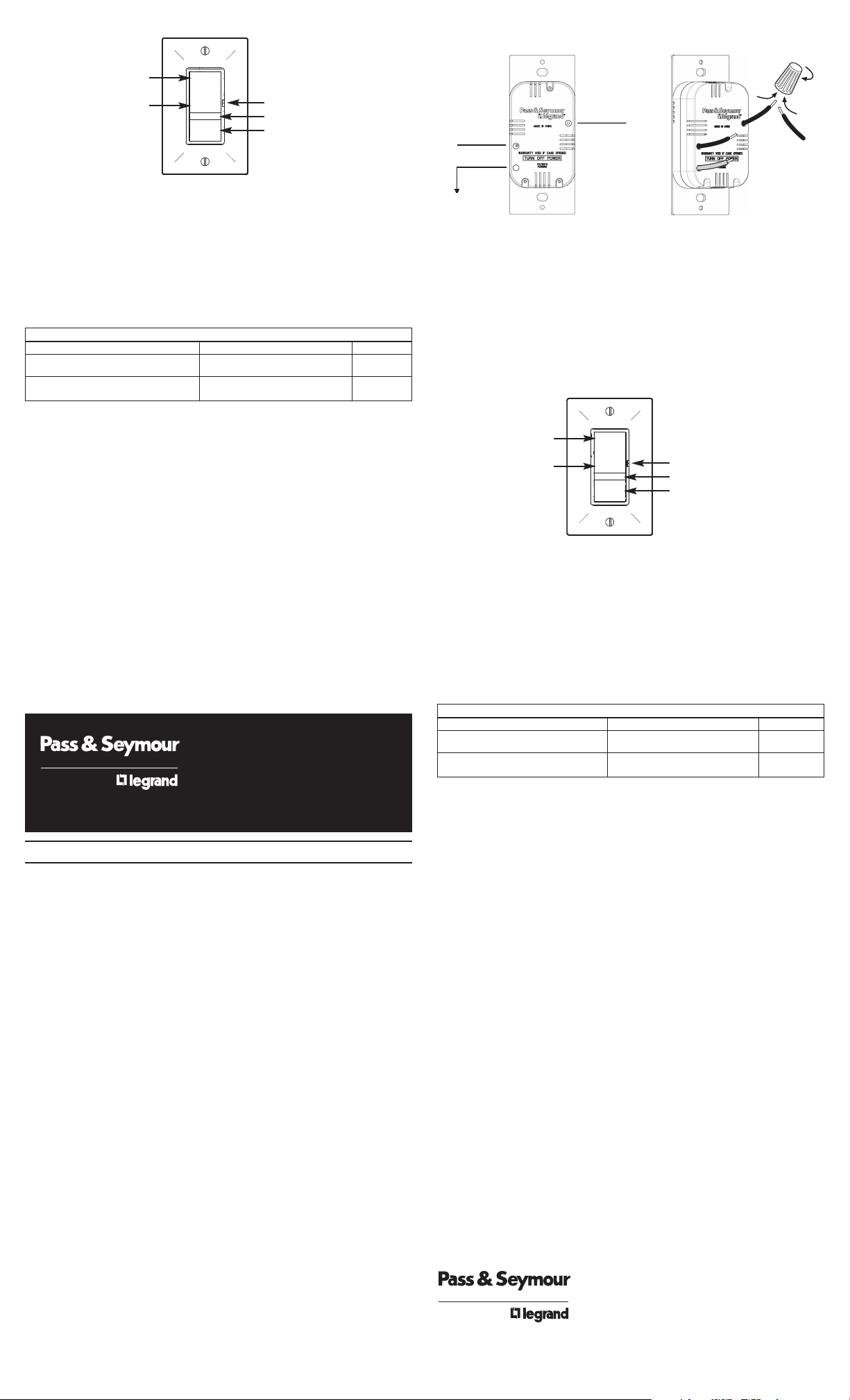
Raccorder à la source
(Noir)
Raccorder à la lampe
(Noir)
FIL DE TERRE
(Vert ou Nu)
Tourner
Diagramme d’installationS héma de âblage
Fon tions du
Lo alisateur
MICRO-INTERRUPTEUR
DEL LUMINEUSE
APPUYER ICI POUR LA
FONCTION DE LOCALISATION
DE LA MAISON
APPUYER ICI POUR
ALLUMER
APPUYER ICI POUR
ÉTEINDRE
Fun iones del
Lo alizador
MICROINTERRUPTOR
ILUMINACIÓN DE LED
PRESIONE AQUÍ
PARA LA FUNCIÓN
DE LOCALI ACIÓN
DE LA CASA
PRESIONE AQUÍ
PARA ENCENDER
PRESIONE AQUÍ
PARA APAGAR
TABLA PARA EL USO DE CAPUCHONES
COMBINACIÓN DE ALAMBRES LONGITUD A PELAR COLOR
1#14 & 1#16; 1#14 & 2#18; 2, 3#16; #14 – 1/2", #16 & #18 – 9/16" NARANJA
1#16 & 1 – 3#18; 3 – 5#18; 2#18
1#14 & 1, 2#16; 1#14 & 1, 2#18; #14 & #16 – 7/16", #18 – 1/2" MARFIL
2, 3#16; 2 – 5#18
TABLEAU D’UTILISATION DES CONNECTEURS DE FILS
COMBINAISON DE FILS LONGUEUR À DÉNUDER COULEUR
1#14 & 1#16; 1#14 & 2#18; 2, 3#16; #14 – 1/2", #16 & #18 – 9/16" ORANGE
1#16 & 1 – 3#18; 3 – 5#18; 2#18
1#14 & 1, 2#16; 1#14 & 1, 2#18; #14 & #16 – 7/16", #18 – 1/2" IVOIRE
2, 3#16; 2 – 5#18