Lenovo P70-A User manual

Service Manual of
Lenovo P70-A Mobile
Phone
Lenovo

Repair Manual of Lenovo P70-A Mobile Phone
1
Document name Service Manual of Lenovo P70-A Mobile Phone
Version: V1.0
Date: Nov 3, 2014
Document No.:
Status:
Preface
This manual is intended for online repair guidance and after-sale repair guidance of
Lenovo P70-A mobile phone produced by the Company
The content of this manual will be upgraded according to the needs of technology
development.
Copyright
The copyright of this manual belongs to Lenovo Mobile; anyone who reproduces this
manual without written consent of the Company shall bear legal responsibility.

Repair Manual of Lenovo P70-A Mobile Phone
2
Content
1.Appearance.............................................................................................................................5
2.Layout of main board.............................................................................................................6
3.Baseband.................................................................................................................................7
4.Main adverse analysis...............................................................................................................8
4.1LCD DISPLAY ...........................................................................................................................8
4.1.1No display on screen after power-on...................................................................................8
4.1.2LCD backlight without lighting ...........................................................................................9
4.2CAMERA DEFECTS...................................................................................................................10
4.2.1Rear camera defects ..........................................................................................................10
4.3RING AND VIBRATION..............................................................................................................11
4.3.1No vibration.......................................................................................................................11
4.3.2No ring...............................................................................................................................12
4.4CHARGING..............................................................................................................................13
4.4.1No charging display after plugging the charger in............................................................13
4.4.2Charging shown but not full charging ...............................................................................14
4.5KEYBOARD AND KEYBOARD BACKLIGHT................................................................................15
4.5.1Abnormal operation of side keys .......................................................................................15
4.5.2Abnormal operation of CTP keyboard...............................................................................16
4.6CALLING.................................................................................................................................17
4.6.1No voice heard from the other side during the call............................................................17
4.6.2No voice heard from your side during the call...................................................................18
4.7POWER-ON FAILURE................................................................................................................19
4.8LCD ON WHEN CLOSE TO THE EAR DURING THE CALL;LCD OFF WHEN AWAY FROM THE EAR.20
4.9RADIO FREQUENCY (RF).........................................................................................................21
4.10SOFTWARE DOWNLOAD FAILURE............................................................................................21
4.11PRODUCTION CALIBRATION ....................................................................................................22
4.11.1AFC calibration.............................................................................................................22
4.11.2AGC...............................................................................................................................23
4.11.3APC ...............................................................................................................................24
4.12FAULT IN COMPLETE SET TEST/REWORK .................................................................................26
4.12.1Switch spectrum & PVT template with excessive standard ...........................................26
4.12.2High Frequency Error ...................................................................................................27
4.12.3High Phase Error ..........................................................................................................27
4.12.4Power output problems..................................................................................................28
4.133G/4G FORECAST ...................................................................................................................29
4.13.1RSSI _Cal ......................................................................................................................29
4.13.2TPC _ Cal......................................................................................................................29
4.143G/4G COMPREHENSIVE TEST.................................................................................................31
4.14.1ACLR or SEM................................................................................................................31
4.14.2ILPC comprehensive test abnormal...............................................................................31

Repair Manual of Lenovo P70-A Mobile Phone
3
4.14.3Frequency Err................................................................................................................31
5.Disassembly Guide..............................................................................................................32
6.Assemble Guide...................................................................................................................40

Version
No. Prepared by/
Modified by
Prepared/
Modified
on
Reason for
change Main changes

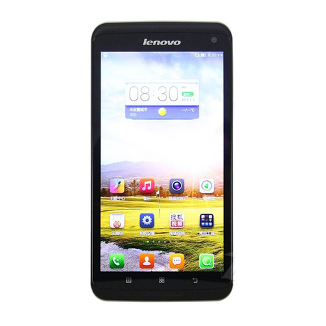
1. Appearance

Repair Manual of Lenovo P70-A Mobile Phone
6
2. Layout of main board
Front of main board:
Back of main board:

Repair Manual of Lenovo P70-A Mobile Phone
7
3. Baseband
Block diagram of hardware system

Repair Manual of Lenovo P70-A Mobile Phone
8
4.Main adverse analysis
4.1 LCD display
4.1.1 Nodisplayonscreenafterpower‐on
White screen or blank screen without display; backlight
with lighting
Check whether the EMI device Z1601--Z1605 of
LCD circuit on main board is solder incompletely;
re-solder EMI device
OK
Check whether there is cold solder joint on other
device around LCD and on LCD connector.
Check the connection of LCD FPC is good and
re-assembled FPC whether phone is normal
N
N
Y
OK
Y
Check the display is normal after replacing LCD,
N
OK
Y

Repair Manual of Lenovo P70-A Mobile Phone
9
4.1.2 LCDbacklightwithoutlighting
Check whether there are voltages more than
24V between both ends of C1612 when LCD
is lit.
OK
If the backlight circuit is
normal, it is the problem
of LCD
Check the welding condition of U1603 and
peripheral devices, including L1601,
D1601, C1612,C1611,R1605,R1606
Y
N
Y
YOK
Check whether the connection of FPC on
LCD module and connector on main board is
good and whether the LCD backlight is
normal after reconnection
N
Re-verify whether the LCD backlight is
normal after replacing LCD. OK
Y
N
LCD backlight without lighting

Repair Manual of Lenovo P70-A Mobile Phone
10
4.2 Camera defects
4.2.1 Rearcameradefects
OK
Check to see whether the EMI
device is complete and welding is
in good condition; if not; repair
EMI device(Z1701—Z1705)
Recheck after replacing front
camera
Check to see whether
the front camera is
abnormal
N
Y
N
N
Recheck after overlaying welding
Y
N
Whether the camera is OK
after replacing the camera
module
Check to see whether the camera
module connector is welded well;
whether the camera is OK after
overlaying welding the connector?
N
YOK
Check to see whether the camera
module is in the right position by
disassembling and whether the module
is OK after reassembling module
N
Y
OK
Check to see whether the main
chip U401 are normally
welded?
Re-weld or replace U401
N
Can not take photos

Repair Manual of Lenovo P70-A Mobile Phone
11
4.3 Ring and vibration
4.3.1 Novibration
Replace the motor to see whether
it is ok? Check to see whether the
circuit around the motor is
normal
(
R1808,C1811
)
OK
Y
N
Check whether the motor is interfered by
structure; Recheck whether it is normal after
reassembling the phone.
OK
Y
No vibration
N
Replace U503 chip
N

Repair Manual of Lenovo P70-A Mobile Phone
12
4.3.2 Noring
Check to see whether the main chip U503 is
damaged. Replace it if damaged.
N
N
Replace Speaker and recheck whether it is
normal?
Check to see whether the SPK circuit is
normal?(D1405,D1406,C1413,B1405,B1406,R
505,R506)
Use earphone to test whether there is sound; if
there is sound from earphone, there is audio
signal to input. Check whether J1803 KB
connector device is of cold solder joint; recheck
whether it is ok after re-welding,Replace the
KB connector FPC to try again
;
OK
OK
OK
Y
Y
Y
No ring

Repair Manual of Lenovo P70-A Mobile Phone
13
4.4 Charging
4.4.1 Nochargingdisplayafterpluggingthechargerin
Check whether the charging is normal
after replacing the charger (J801). Replace the charger
No charging display after
plugging the charger in
N
Y
Replace the battery and see whether the
charging is normal? Measure the battery
volta
g
e to see whether it is less than 3V
Replace the battery
Y
N
Check to see whether U630 module
device is well welded? Whether it is
normal after re-welding
Y
OK
N
Replace U503 YOK

Repair Manual of Lenovo P70-A Mobile Phone
14
4.4.2 Chargingshownbutnotfullcharging
Check to see the Voltage of VCHG is
normal (5.0V), Check the VCDT Circuit
& ISENSE Circuit components is normal
(R523, R524, R551, R571,R663,R662 )
Replace U630 module device and
then recheck
Re
p
lace U503
Replace the battery and then check whether it
is fully charged
Charging shown but not
full charging
OK
Y
N
N
N
OK
Y
OK
Y
Re-solder the USB connector
or change for another FPC ;
Re-solder or change the
components which is damaged
or in poor soldering
Y

Repair Manual of Lenovo P70-A Mobile Phone
15
4.5 Keyboard and keyboard backlight
4.5.1 Abnormaloperationofsidekeys
N
Abnormal side key
Re
p
lace U401/U503
Check whether there are conditions like cold
solder joint and short circuit on keyboard
FPC ? Whether it is ok after re-welding?
Check whether there are conditions like cold solder
joint and missing device on the circuit device of side
keys and power key .
( R1806,R1807,D1802,D1803,R1801,D1801,C1801 )
Y
O
K
N
OK
YOK
FPC is fracted, Replace
side keys FPC
N

Repair Manual of Lenovo P70-A Mobile Phone
16
4.5.2 AbnormaloperationofCTPkeyboard
CTP keyboard is invalid
Whether the CTP test is normal?
It is the problem of CTP connector J1601
or main chip U401 welding
CTP damaged,
replace it
Y
Replace CTP
Y
N
N
Replace one CTP to see whether
it is the problem of touch screen
or main board?

Repair Manual of Lenovo P70-A Mobile Phone
17
4.6 Calling
4.6.1 Novoiceheardfromtheothersideduringthecall
No voice heard from the other
side durin
g
the call
Replace the headphones and then re
check whether it is normal
N
Y
OK
N
Replace U503
Check whether
B1403,B1404,C1428,C1427,D1403,D140
4,are well welded. Re-weld and test
Use earphone and hands-free to verify
whether there is voice?
N Cold solder joint
of main
chip(U503) or
main chip(U503)
is abnormal
Y Y OK

Repair Manual of Lenovo P70-A Mobile Phone
18
4.6.2 Novoiceheardfromyoursideduringthecall
Re-weld
Check U503 and
C1402,C1403,R1401,R1402,R1403R1404 is OK
N
No voice heard from your side during the call
Check whether receiver and the peripheral devices are
well welded; whether it is ok after re-welding?
Y
Check whether receiver module device is well
welded. Replace this device and see whether it is
ok? OK
N
Y

Repair Manual of Lenovo P70-A Mobile Phone
19
4.7 Power-on failure
Failed to Power-on
Check whether the 26MHz on X801
is normal? Whether there is 26MHz
signal
Check whether X801 is well
welded
Y
N Re-weld and recheck
Re-weld and recheck
N
Replace the main chip U503
Y
Power on the phone on separate main
board , whether there is high current?
N
YThe main board is damaged;
replace the main board and check
the failure board step by step
Check whether the power key FPC is
assembled well , reassembling the
p
ower FPC ?
N
YRe-weld
Y
Check whether the main power supply of U503 is
normal?
(VCORE,VPROC,VIO18,VTCXO,VIO28,VRF
28,VRF18,VMC, etc.)
NRe-weld or
replace device
U301 to recheck
Table of contents
Other Lenovo Cell Phone manuals

Lenovo
Lenovo X2-EU User manual

Lenovo
Lenovo PHAB2 How to use

Lenovo
Lenovo A526 User manual

Lenovo
Lenovo A6010 User manual

Lenovo
Lenovo A606 User manual

Lenovo
Lenovo K320t User manual

Lenovo
Lenovo A269i User manual

Lenovo
Lenovo VIBE P1m SERIES User manual

Lenovo
Lenovo P1A42 User manual

Lenovo
Lenovo C2 POWERK10a40 User manual

Lenovo
Lenovo K8 Plus User manual

Lenovo
Lenovo motorola DROID TURBO User manual

Lenovo
Lenovo C2 Series User manual

Lenovo
Lenovo A6000 User manual

Lenovo
Lenovo A7010 User manual

Lenovo
Lenovo S920 User manual

Lenovo
Lenovo A319 User manual

Lenovo
Lenovo A7700 User manual

Lenovo
Lenovo A6010 User manual

Lenovo
Lenovo VIBE C2 User manual