Einbau des LE0511A
Notieren Sie sich, welcher Motoranschluß mit den rechten und welcher
mit den linken Radschleifern verbunden ist. Dies erspart Ihnen beim
Anschluß des Lokempfängers Versuche, welches Kabel des
Lokempfängers an welchen Motoranschluß gelötet werden muß, um die
richtige Fahrtrichtung einzustellen.
Die Motoranschlüsse müssen nach Entfernen der bisherigen Kabel
potentialfrei sein. Das heißt, sie dürfen keine Verbindung zum Chassis
oder den Lokrädern (Radschleifern) mehr haben. Achten Sie auch darauf,
daß solche Verbindungen mitunter erst durch Aufsetzen des Gehäuses
entstehen können!
Wenn Sie sich nicht sicher sind, ob alle Voraussetzungen zum Einbau
erfüllt sind, wenden Sie sich an einen Servicebetrieb.
Schließen Sie den Lokempfänger zuerst an die Radschleifer an:
rotes Kabel an die in Fahrtrichtung rechten Radschleifer
schwarzes Kabel an die in Fahrtrichtung linken Radschleifer.
Dann verbinden Sie den Empfänger mit den Motoranschlüssen:
oranges Kabel an den Motoranschluß, der vorher mit den rechten
Radschleifern verbunden war
graues Kabel an den Motoranschluß, der vorher mit den linken
Radschleifern verbunden war.
Nun schließen Sie die Funktionen an. Im Auslieferungszustand sind
diese Funktionsausgänge wie folgt eingestellt: Ausgänge A und B
reagieren fahrtrichtungsabhängig auf F0. Diese Einstellung kann geändert
werden.
Wenn Sie die Funktionsausgänge in der Werkseinstellung verwenden
möchten, dann verbinden Sie die Ausgänge wie folgt:
Funktionsausgang A (weißes Kabel) an das in Fahrtrichtung vordere
Birnchen,
Funktionsausgang B (gelbes Kabel) an das in Fahrtrichtung hintere
Birnchen.
Sind die Glühbirnchen nicht elektrisch mit dem Chassis der Lokomotive
verbunden (wir nennen diese dann "potentialfrei"), so schließen Sie nun
noch den anderen Pol der Lampen an das blaue Kabel an, wie in der
Abbildung zu sehen. Besteht eine Verbindung zwischen Glühbirnen und
Chassis, so bleibt das blaue Kabel unbenutzt. Bei Anschluß am blauen
Kabel leuchten die Glühbirnen etwas heller, außerdem funktioniert dann
die richtungsabhängige Beleuchtung auch im Betrieb mit normalem
Gleichstrom. Welche der Varianten Sie umsetzen, hängt von der
Konstruktion der Lokomotive ab.
Für den Anschluß von Leuchtdioden gilt: Blaues Kabel ist der "Pluspol"
(Anodenseite der LED), Funktionsausgang ist der "Minuspol"
(Kathodenseite der LED). Die Spannung am Funktionsausgang beträgt
ca. 16V. Vergessen Sie nicht den erforderlichen Vorwiderstand.
l
l
l
l
l
l
Installation of the LE0511A
Take note of which motor connection is linked to the right-hand
locomotive wheels and which to the left. If you do this you will not have to
try out which cable of the decoder needs to be soldered to which
connection of the motor in order to achieve the desired direction of travel.
After the removal of the original connections to the motor brushes, both
the motor brushes must be potential free and completely isolated from
both tracks. This means that they must not be connected in any way to the
chassis or to the wheels of the locomotive. Also bear in mind that such
connections are sometimes created only when the chassis is put back!
Please contact a service centre if you are in any doubt as to whether all
preconditions for the installation are fulfilled!
First connect the decoder to the pick-ups from the wheels of the
locomotive:
red cable to the wheels which in relation to the direction of travel are
on the right-hand side of the locomotive
black cable to the wheels which in relation to the direction of travel
are on the left-hand side of the locomotive
Then connect the decoder to the motor connections:
orange cable to the motor connection previously connected to the
right-hand locomotive wheels
grey cable to the motor connection previously connected to the left-
hand locomotive wheels.
Now connect the functions. Ex-works default settings for the functions
are configured as follows: function outputs A and B as direction-
dependent outputs reacting to F0. This configuration can be altered as
desired.
If you wish to use the function outputs in their initial configuration then
connect the outputs as follows:
function output A (white cable) to the bulb which in relation to the
direction of travel is at the front
function output B (yellow cable) to the bulb which in relation to the
direction of travel is at the back
If the functions inside the locomotive (e.g. the bulbs of the direction
dependent lights) are not electrically connected to the chassis of the
locomotive (i.e; if they are, "potential free") then connect the other pole of
the function to the blue cable, as shown in the illustration. If a connection
between functions and chassis does exist, then the blue cable remains
unused. When connected to the blue cable the bulbs shine somewhat
brighter and, in addition, the direction dependent lighting then also works
in normal DC operation. Which option you choose depends on the design
of the locomotive.
For the connection of LEDs note that the blue cable is the positive pole
(anode side of the LED) and the function output the negative pole
(cathode side of the LED). The voltage at the function output is approx.
16 V. Please do not forget the necessary protective resistor.
l
l
l
l
l
l
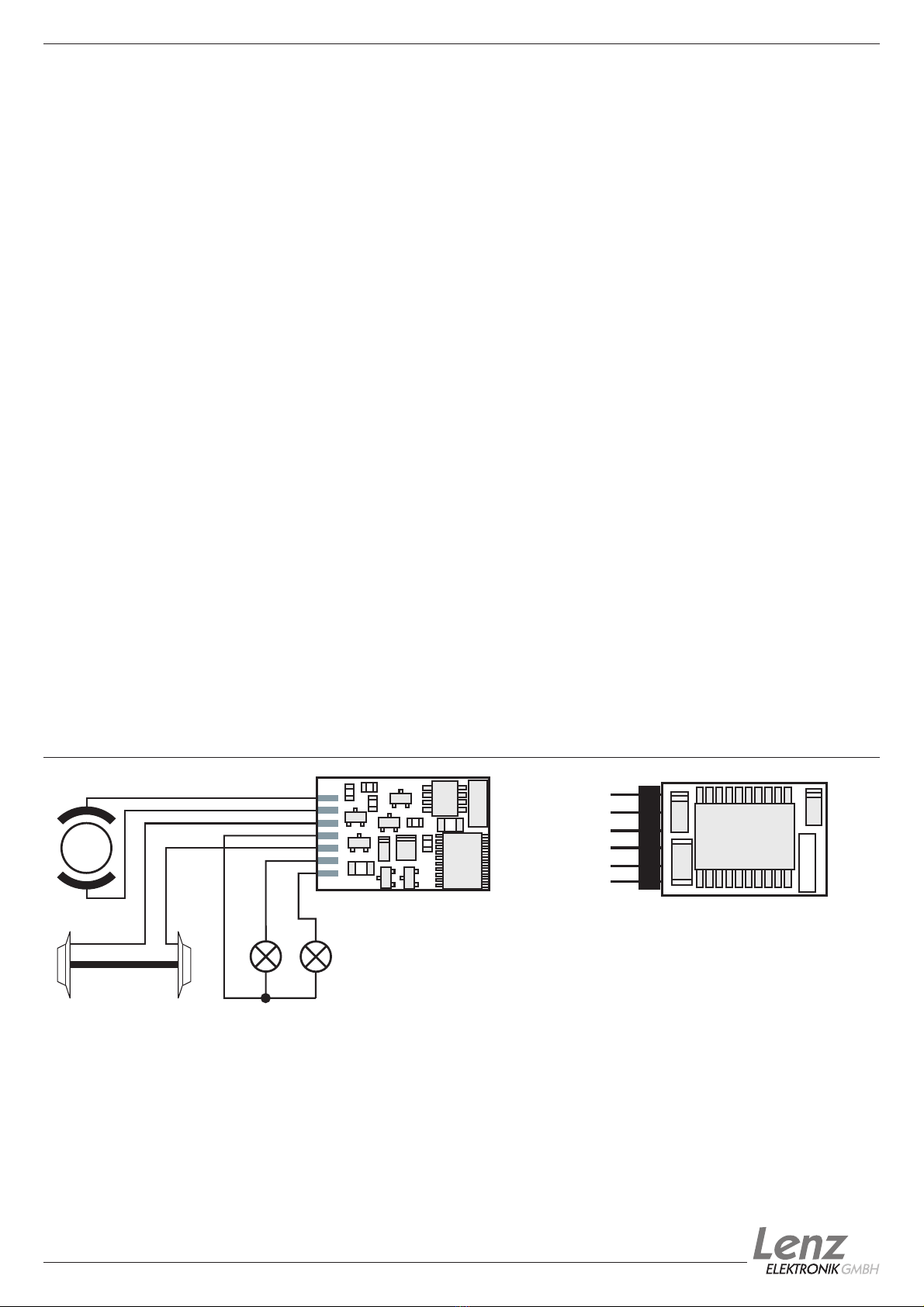
Motor
AB
Schwarz
Black
Orange
Grau
Grey Rot Weiß
White
Gelb
Yellow
Blau
Blue
Anschluß des /
LE0511A
Wiring the
Schnittstelle des / Plug of
LE0511D
the
Seite / Page: 2
Information LE0511A / LE0511D
Pin 1
Pin 6
Einbau des LE0511D
Der Schnittstellenstecker gemäß NEM 651 ermöglicht einen schnellen
und problemlosen Umbau von Lokomotiven.
Ziehen Sie den Brückenstecker von der Schnittstelle der Lokomotive
ab. Bewahren Sie diesen Stecker sorgfältig auf. Stecken Sie nun den
Stecker des Lokempfängers so auf die Schnittstelle auf, daß Pin 1 an der
aus der Betriebsanleitung der Lok zu erkennenden Stelle zu liegen
kommt.
Pin 1 in der Zeichnung oben.
Achten Sie darauf, daß Sie beim Einstecken keinen der Steckerstifte
verbiegen oder gar abbrechen.
Pin 1 des Decoders ist weiß gekennzeichnet, außerdem sehen
Sie die Lage des
Installation of the LE0511D
These decoders come with a NEM651 plug.This plug makes installation
of these decoders very simple.
To install the decoder simply remove the dummy plug in your
locomotive and install the decoder plug. To ensure the headlights work
properly you must align the plug properly. The position of Pin 1 is shown
above and marked on the decoder. Ensure this is aligned to pin one of the
locomotive. Pin 1 is marked on the decoder and you can see the position
on the picture above.
Be careful when installing the plug so that the pins will not be bent or
broken.


