Lenze EPM-H410 User manual

Bedieneinheit EPM-H410
MA H410
-1-
Diese Anleitung
é
enthält die wichtigsten Technischen Daten, beschreibt die Installation, die
Handhabung und die Inbetriebnahme der Bedieneinheit.
é
ist nur gültig für die Bedieneinheit mit der Typenschildbezeichnung EPM-H410.
Beschreibung
Mit der Bedieneinheit H410 können Sie auf Codestellen der Antriebsregler von Lenzezu-
greifen.Mit dem ProjektierungstoolHMI Designer legenSiefest,welcheCodestellenüber
die Bedieneinheit bearbeitet bzw. verändert werden sollen.
Einsatzbereich
Einsetzbar mit den Antriebsreglern der Gerätereihen:
é
Frequenzumrichter 8200 (mit Funktionsmodul AIF)
é
Frequenzumrichter 8200 vector
é
Servo-Umrichter 93XX
Die Verbindung zu den Antriebsreglern erfolgt über Systembus (CAN).
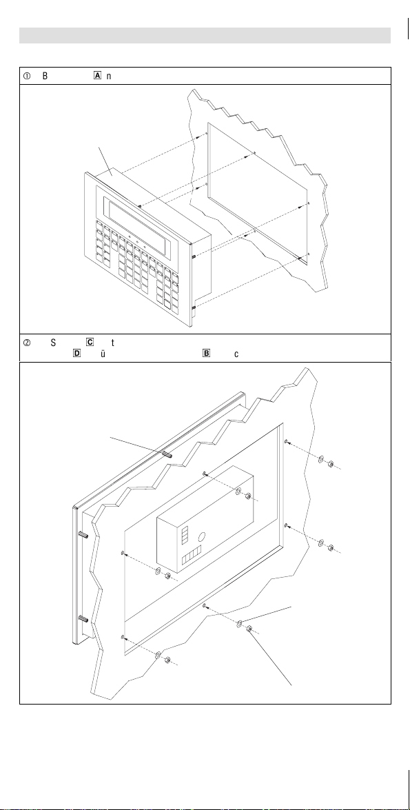
Zubehör
Beliegend befindet/befinden sich
- sechs Sechskantmuttern M4
- sechs U-Scheiben M4
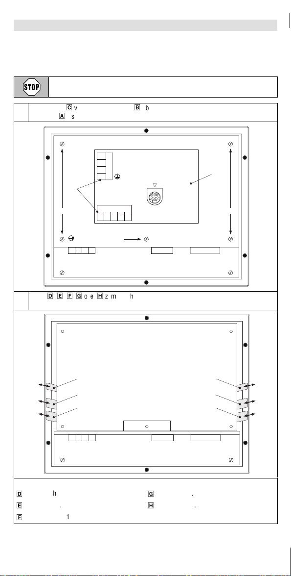
- zwei Klemmleisten 4pol. für Anschluß DC-Spannungsversorgung
- eine Klemmleiste 5pol. für Anschluß Systembus (CAN)
- ein Systembus-Interface Anschlußkabel EPZ-H112
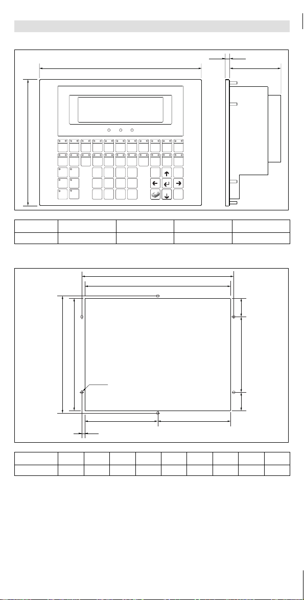
Allgemeine Daten und Einsatzbedingungen
Display Graphic (240 x 64 pixel)
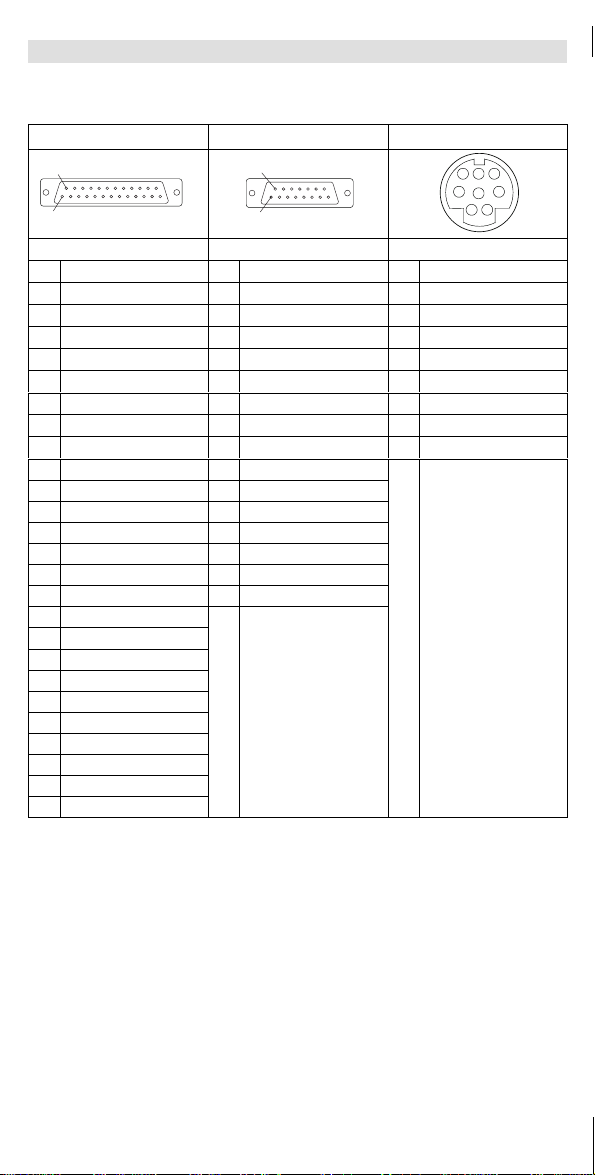
Elektrischer Anschlußsteckbare Schraubklemmen
DC-Spannungsversorgung 18 VDC ... 32 VDC
Leistungsaufnahme 11 Wbei 24 VDC
Isolationsspannung zur Bezugserde/PE 50 V AC
Schutzart IP65 (Front)
Systembus
(CAN) Protokoll CANopen
(CAL basierendes Kommunikationsprofil DS301)
(
C
A
N
)
Kommunikationsmedium DIN ISO 11898
Netzwerk-Topologie Linie (beidseitig abgeschlossen mit 120 Ω)
Systembus-Teilnehmer Master oder Slave
max. Anzahl Teilnehmer 63
Baudrate [kBit/s] 20 50 125 250 500
max. Buslänge [m] 2500 1000 500 250 80
Umgebungstemperatur im Betrieb: 0 ... +50 °C
Transport: -20 ... +60 °C
Lagerung: -20 ... +60 °C
Klimatische Bedingungen Klasse 3K3 nach EN 50178 (ohne Betauung, mittlere
relative Feuchte 90 %)
Gewicht 1.2 kg
EDKEPMH410
00414159
03/00
Show/Hide Bookmarks

Abmessungen
MA H410
-2-
a
d
e
b
F1
F12
F23
Alarm
Help
Info shift
BatteryPower
·±
Space
VWX
7
MNO
4
ABC
0
DEF
1
GHI
1
JKL
2
Enter
Spare Clr
Esc
PQR
5
STU
6
YZ-
8
+/=
9
F2
F13
F24
F3
F14
F4
F15
F5
F16
F6
F17
F7
F18
F8
F19
F9
F20
F10
F21
F11
F22
Bus Error
Ack All
Ack
PgUp
PgDN
410_01
amm bmm dmm emm
EPZ-H410 252.0 196.0 5.0 100.0
Einbauausschnitt
410_02
a
gg
h
b
Æk
d
e
e
f
c
a b c d e f g h k
[mm] 232.0 178.0 242.0 186.0 29.0 120.0 116.0 5.0 4.5
Show/Hide Bookmarks

Mechanische Installation
MA H410
-3-
Bedieneinheit
0
in den Einbauausschnitt schieben.
H410_03a
0
ó
U-Scheiben
2
(6 Stück) aufstecken.
Muttern
3
(6 Stück) auf die Gewindebolzen
1
(6 Stück) drehen und festziehen.
H410_03b
2
1
3
Show/Hide Bookmarks

Klemmenbelegung
MA H410
-4-
é
Beschädigung angeschlossener Geräte. Verbinden Sie den PE-Leiter so wie es in der
Abbildung dargestellt ist!
é
Bedieneinheit nur im spannungslosen Zustand verdrahten!
+24 VDC
0 VDC
N.C.
1
2
3
4
N.C.
CAN+
Shield
CAN-
V-
12345
+24 VDC
0 VDC
N.C.
1234
ASP8
ASP
INPUT VOLTAGE: 18 - 32 V 11 W
FUSE 800 mA
MSP
~
+
-24 V
PE
N
L1
CAN-GND
CAN-LOW
CAN-HIGH
410_0
4
DC-Spannungsversorgung
Klemme Bezeichnung Erläuterung
1+24VDC Versorgungsspannung (18 V ... 32 VDC)
20VDC GND Versorgungsspannung, Bezugspotential
3N.C. Nicht angeschlossen
4PE-Potential
Systembus (CAN)
Klemme Bezeichnung Erläuterung
1V- GND Bezugspotential
2CAN- LO Systembus LOW (Datenleitung)
3Shield Schirm des Systembus-Kabel auflegen
4CAN+ HI Systembus HIGH (Datenleitung)
5N.C. Nicht angeschlossen
Show/Hide Bookmarks

Verdrahtung Systembus
MA H410
-5-
Prinzipieller Aufbau
410_0
6
H410
ShieldCAN--V CAN+ N.C. CG LO HI CG LO
CG LO HI CG LO HI HI
120
120
01
0
Antriebsregler 1
1
Antriebsregler 2
Spezifikation Systembus-Kabel
Gesamtlänge ≤300 m ≤1000 m
Kabeltyp LIYCY2x2x0,5mm
2
(paarverseilt mit Abschirmung) CYPIMF2x2x0,5mm
2
(paarverseilt mit Abschirmung)
Leitungswiderstand ≤40 Ω/km ≤40 Ω/km
Kapazitätsbelag ≤130 nF/km ≤60 nF/km
Anschluß Paar 1 (weiß/braun): LO und HI
Paar 2 (grün/gelb): GND
Beim ersten und letzten Teilnehmer in einem Systembus mußein
Abschlußwiderstand von 120 Ωzwischen den Klemmen CAN-LOW und
CAN-High angeschlossen werden.
Show/Hide Bookmarks

PC anschließen
MA H410
-6-
Die Verbindung zwischen PC und Bediengerät nur bei ausgeschalteten Geräten herstel-
len!
l
HMI Designer
+24 VDC
0 VDC
N.C.
1
2
3
4
N.C.
CAN+
Shield
CAN-
V-
12345
+24 VDC
0 VDC
N.C.
1234
ASP8
ASP
0
1
INPUT VOLTAGE: 18 - 32 V 11 W
FUSE 800 mA
MSP
410_05
Schritt
1Downloadkabel EPZ-H110
0
auf MSP-Schnittstelle stecken.
2Downloadkabel EPZ-H110
0
auf COM1 oder COMx
1
am PC stecken.
Show/Hide Bookmarks

PC anschließen
MA H410
-7-
Schnittstellenbeschreibung
MSP ASP ASP8
1
14
1
9
12
3
4
5
678
DB25 Buchse DB15 Buchse Minidin 8pol. Buchse
Pin Signal Pin Signal Pin Signal
1N.C. 1DCD IN 1Rx RS232 IN
2Tx RS232 OUT 2RX IN 2Tx RS232 OUT
3Rx RS232 IN 3TX OUT 3N.C.
4RTS RS232 OUT 4DTR OUT 4RTS RS232 OUT
5CTS RS232 IN 5Signal GND 5CTS RS232 IN
6N.C. 6N.C. 6N.C.
7Signal GND 7Signal GND 7Signal GND
8N.C. 8Tx Rx485 + IN/OUT 8+5VCC(reserved)
9Tx C.L. + OUT *9DSR IN
10 Tx Rx485 -IN/OUT 10 RTS OUT
11 Tx C.L. -OUT *11 CTS IN
12 Tx RS422 -OUT 12 RI IN
13 Rx RS422 + IN 13 N.C.
14 IKT OUT 14 N.C.
15 IKR oUT 15 Tx Rx485 -IN/OUT
16 +5VCC(reserved)
17 N.C.
18 Rx C.L. + IN *
19 N.C.
20 N.C.
21 N.C.
22 Tx Rx485 + IN/OUT
23 Tx Rx422 + OUT
24 Tx Rx422 -IN
25 Rx C.L. -IN *
*
N.C. C.L. = Current Loop (TTY)
Nicht angeschlossen
Show/Hide Bookmarks

Tastatur beschriften
MA H410
-8-
Die Tastatur kann mit auswechselbaren Schildern beschriftet werden. Zum Wechseln
bzw. zum Beschreiben der Schilder müssen Sie den Gehäusedeckel der Bedieneinheit
öffnen.
Vor dem Öffnen des Gehäuses Spannungsversorgung abschalten!
1. Klemmleisten
2
vom Systembus-Modul
1
abziehen.
Schrauben
0
lösen und Gehäusedeckel mit Systembus-Modul abnehmen.
410_09a
00
0
2
1
+24 VDC
0 VDC
N.C.
1
2
3
4
N.C.
CAN+
Shield
CAN-
V-
12345
+24 VDC
0 VDC
N.C.
1234
ASP8
ASP
INPUT VOLTAGE: 18 - 32 V 11 W
FUSE 800 mA
MSP
2. Schild
3
,
4
,
5
,
6
oder
7
zum Beschriften aus dem Schlitz ziehen.
Anschließend beschriftetes Schild in den Schlitz schieben.
520_09
ASP MSP
33
45
67
Zuordnung der Schilder:
3
Kennzeichnung der Bedieneinheit
6
Tasten F12 ... F16
4
Tasten F1 ... F5
7
Tasten F17 ... F22
5
Tasten F6 ... F11
Show/Hide Bookmarks

Inbetriebnahme
MA H410
-9-
Für die Inbetriebnahme ist eine vollständige Verdrahtung des Systembus notwendig.
Überprüfen Sie vor dem Einschalten der Versorgungsspannung
é
die gesamte Verdrahtung auf Vollständigkeit und Kurzschluß.
é
ob das Bussystem beim physikalisch ersten und letzten Busteilnehmer abgeschlos-
sen ist.
Erstes Einschalten der Bedieneinheit und Laden eines Projektes
1. PC einschalten und Projektierungstool HMI
Designer starten.
2. Versorgungsspannung für Bedieneinheit
einschalten.
F1
F12
F23
Alarm
Help
Info shift
BatteryPowerBus Error
·±
Space
VWX
7
MNO
4
ABC
0
DEF
1
GHI
1
JKL
2Enter
Spare Clr
Esc
PQR
5
STU
6
YZ-
8
+/=
9
F2
F13
F24
F3
F14
F4
F15
F5
F16
F6
F17
F7
F18
F8
F19
F9
F20
F10
F21
F11
F22
1
0
Ack All
Ack
PgUp
PgDN
“Press Enter to Download” wird an-
gezeigt.
F1
F12
F23
Alarm
Help
Info shift
BatteryPowerBus Error
·±
Space
VWX
7
MNO
4
ABC
0
DEF
1
GHI
1
JKL
2Enter
Spare Clr
Esc
PQR
5
STU
6
YZ-
8
+/=
9
F2
F13
F24
F3
F14
F4
F15
F5
F16
F6
F17
F7
F18
F8
F19
F9
F20
F10
F21
F11
F22
1
0
Ack All
Ack
PgUp
PgDN
3. Enter-Taste
1
drücken.
F1
F12
F23
Alarm
Help
Info shift
BatteryPowerBus Error
·±
Space
VWX
7
MNO
4
ABC
0
DEF
1
GHI
1
JKL
2Enter
Spare Clr
Esc
PQR
5
STU
6
YZ-
8
+/=
9
F2
F13
F24
F3
F14
F4
F15
F5
F16
F6
F17
F7
F18
F8
F19
F9
F20
F10
F21
F11
F22
1
0
Ack All
Ack
PgUp
PgDN
3
.
Im Display wird die Aufforderung zum
Download über die MSP-Schnittstelle
angezeigt.
F1
F12
F23
Alarm
Help
Info shift
BatteryPowerBus Error
·±
Space
VWX
7
MNO
4
ABC
0
DEF
1
GHI
1
JKL
2Enter
Spare Clr
Esc
PQR
5
STU
6
YZ-
8
+/=
9
F2
F13
F24
F3
F14
F4
F15
F5
F16
F6
F17
F7
F18
F8
F19
F9
F20
F10
F21
F11
F22
1
0
Ack All
Ack
PgUp
PgDN
4. F2-Taste
0
drücken.
F1
F12
F23
Alarm
Help
Info shift
BatteryPowerBus Error
·±
Space
VWX
7
MNO
4
ABC
0
DEF
1
GHI
1
JKL
2Enter
Spare Clr
Esc
PQR
5
STU
6
YZ-
8
+/=
9
F2
F13
F24
F3
F14
F4
F15
F5
F16
F6
F17
F7
F18
F8
F19
F9
F20
F10
F21
F11
F22
1
0
Ack All
Ack
PgUp
PgDN
4
.
“Waiting for Download” wird ange-
zeigt.
F1
F12
F23
Alarm
Help
Info shift
BatteryPowerBus Error
·±
Space
VWX
7
MNO
4
ABC
0
DEF
1
GHI
1
JKL
2Enter
Spare Clr
Esc
PQR
5
STU
6
YZ-
8
+/=
9
F2
F13
F24
F3
F14
F4
F15
F5
F16
F6
F17
F7
F18
F8
F19
F9
F20
F10
F21
F11
F22
1
0
Ack All
Ack
PgUp
PgDN
5. Gewünschtes Projekt vom HMI Designer in
die Bedieneinheit laden.
F1
F12
F23
Alarm
Help
Info shift
BatteryPowerBus Error
·±
Space
VWX
7
MNO
4
ABC
0
DEF
1
GHI
1
JKL
2Enter
Spare Clr
Esc
PQR
5
STU
6
YZ-
8
+/=
9
F2
F13
F24
F3
F14
F4
F15
F5
F16
F6
F17
F7
F18
F8
F19
F9
F20
F10
F21
F11
F22
1
0
Ack All
Ack
PgUp
PgDN
&
“HMI Designer - Erste Schritte”
F1
F12
F23
Alarm
Help
Info shift
BatteryPowerBus Error
·±
Space
VWX
7
MNO
4
ABC
0
DEF
1
GHI
1
JKL
2Enter
Spare Clr
Esc
PQR
5
STU
6
YZ-
8
+/=
9
F2
F13
F24
F3
F14
F4
F15
F5
F16
F6
F17
F7
F18
F8
F19
F9
F20
F10
F21
F11
F22
1
0
Ack All
Ack
PgUp
PgDN
6. PC ausschalten.
7. Versorgungsspannung für Bedieneinheit
abschalten.
Das Projekt bleibt gespeichert.
8. Downloadkabel EPZ-H110 an der Bedie-
neinheit und am PC abziehen.
9. MSP- und ASP8-Schnittstelle mit System-
bus-Interface Anschlußkabel EPZ-H112
2
verbinden.
+24 VDC
0 VDC
N.C.
1
2
3
4
N.C.
CAN+
Shield
CAN-
V-
123 45
+24 VDC
0 VDC
N.C.
123 4
ASP8
ASP
INPUT VOLTAGE: 18 - 32 V 11 W
FUSE 800 mA
2
MSP
10. Versorgungsspannung für Bedieneinheit einschalten.
1
0
.
Bedieneinheit ist betriebsbereit und kann über den Systembus mit den angeschlossenen
Teilnehmern Daten austauschen.
Show/Hide Bookmarks

Batterie wechseln
MA H410
-10-
é
Eine geräteinterne Batterie sorgt dafür, daßEinstellungen sowie die Systemzeit der
Bedieneinheit bei abgeschalteter Spannungsversorgung erhalten bleiben.
é
Wenn die LED “Battery” an der Bedieneinheit leuchtet, müssen Sie die Batterie
auswechseln.
é
Daten der Batterie:
- Lithium-Batterie 3 V, ∅19 mm
- Bestellnummer: EPZ-H600
é
Vor dem Öffnen des Gehäuses Spannungsversorgung abschalten!
é
Um Datenverlust zu vermeiden, muß nach Entnahme der leeren Batterie innerhalb
30 Minuten eine neue Batterie eingelegt werden.
1. Klemmleisten
2
vom Systembus-Modul
1
abziehen.
Schrauben
0
lösen und Gehäusedeckel mit Systembus-Modul abnehmen.
410_09a
00
0
2
1
+24 VDC
0 VDC
N.C.
1
2
3
4
N.C.
CAN+
Shield
CAN-
V-
12345
+24 VDC
0 VDC
N.C.
1234
ASP8
ASP
INPUT VOLTAGE: 18 - 32 V 11 W
FUSE 800 mA
MSP
2. Bügel
4
anheben und Batterie
3
entnehmen.
Bügel anheben und neue Batterie einlegen (Bügel ist Plus-Anschluß).
410_09b
ASP MSP
3
4
+
Show/Hide Bookmarks

Keypad EPM-H410
MA H410
-1-
These Instructions
é
contain the most important technical data and describe installation, operation and
commissioning of the keypad.
é
are only valid for keypads with the nameplate data: EPM-H410.
Description
The H410 keypad enables the user to access codes of Lenze controllers. Use the HMI
Designer to select thecodes to be changed and codesetting through the keypad.
Range of application
Applicable with the following controller series:
é
8200 frequency inverters (with function module AIF)
é
8200 vector frequency inverters
é
93XXservos
Connection with the controllers via system bus (CAN).
Accessories
Included in the delivery package:
- Six hex nuts M4
- Six washers M4
- Two terminal strips, 4-pole, for DC voltage supply
- One terminal strip, 5-pole, for system-bus connection
- One system bus interface connection cable EPZ-H112
General data and application conditions
Display Graphics (240 x 64 pixel)
Electrical connection Pluggable screw terminals
DC voltage supply 18 VDC ... 32 VDC
Power consumption 11 W at 24 VDC
Insulation voltage to reference
earth/PE 50 V AC
Type of protection IP65 (front)
System bus
(CAN) Protocol CANopen
(CAL based communication profile DS301)
(
C
A
N
)
Communication medium DIN ISO 11898
Network topology Line (terminated at both ends with 120 Ω)
System bus participants Master or slave
Max. number of
participants 63
Baud rate [kBit/s] 20 50 125 250 500
Max. bus length [m] 2500 1000 500 250 80
Ambient temperature during operation: 0 ... + 50 °C
during transport: -20 ... +60 °C
during storage -20 ... +60 °C
Climatic conditions Class 3K3 to EN 50178 (without condensation, average
relative humidity 90 %)
Weight 1.2 kg
EDKEPMH410
00414159
03/00
Show/Hide Bookmarks

Dimensions
MA H410
-2-
a
d
e
b
F1
F12
F23
Alarm
Help
Info shift
BatteryPower
·±
Space
VWX
7
MNO
4
ABC
0
DEF
1
GHI
1
JKL
2
Enter
Spare Clr
Esc
PQR
5
STU
6
YZ-
8
+/=
9
F2
F13
F24
F3
F14
F4
F15
F5
F16
F6
F17
F7
F18
F8
F19
F9
F20
F10
F21
F11
F22
Bus Error
Ack All
Ack
PgUp
PgDN
410_01
amm bmm dmm emm
EPZ-H410 252.0 196.0 5.0 100.0
Mounting cut-out
410_02
a
gg
h
b
Æk
d
e
e
f
c
a b c d e f g h k
[mm] 232.0 178.0 242.0 186.0 29.0 120.0 116.0 5.0 4.5
Show/Hide Bookmarks

Mechanical installation
MA H410
-3-
Insert the keypad
0
into the mounting cut-out
H410_03a
0
ó
Use U washers
2
(6 pcs).
Bolt the nuts
3
(6 pcs.) onto threaded bolts
1
(6 pcs.) and tighten them.
H410_03b
2
1
3
Show/Hide Bookmarks

Terminal assignment
MA H410
-4-
é
Damage of units connected. Connect the PE conductor as shown in the picture!
é
Wire the keypad when no voltage is applied!
+24 VDC
0 VDC
N.C.
1
2
3
4
N.C.
CAN+
Shield
CAN-
V-
12345
+24 VDC
0 VDC
N.C.
1234
ASP8
ASP
INPUT VOLTAGE: 18 - 32 V 11 W
FUSE 800 mA
MSP
~
+
-24 V
PE
N
L1
CAN-GND
CAN-LOW
CAN-HIGH
410_0
4
DC voltage supply
Terminal Name Explanation
1+24VDC Voltage supply (18 V ... 32 VDC)
20VDC GND voltage supply, reference potential
3N.C. Not connected
4PE potential
System bus (CAN)
Terminal Name Explanation
1V- GND Reference potential
2CAN- LO System bus LOW (data cable)
3Shield Connect the shield of the system bus cable
4CAN+ HI System bus HIGH (data cable)
5N.C. Not connected
Show/Hide Bookmarks

System bus wiring
MA H410
-5-
Structure in principle
410_0
6
H410
ShieldCAN--V CAN+ N.C. CG LO HI CG LO
CG LO HI CG LO HI HI
120
120
01
0
Controller 1
1
Controller 2
Specification for system bus cable
Total length ≤300 m ≤1000 m
Cable type LIYCY2x2x0.5mm
2
(twisted in pairs with shield) CYPIMF2x2x0.5mm
2
(twisted in pairs with shield)
Cable resistance ≤40 Ω/km ≤40 Ω/km
Capacitance per unit length ≤130 nF/km ≤60 nF/km
Connection Pair 1 (white/brown): LO and HI
Paar 2 (green/yellow): GND
A terminating resistance of 120 Ωmust be connected between the
terminals CAN-LOW and CAN-High at the first and last participant of a
system bus.
Show/Hide Bookmarks

PC connection
MA H410
-6-
PC and keypad must only be connected when the units are switched off!
l
HMI Designer
+24 VDC
0 VDC
N.C.
1
2
3
4
N.C.
CAN+
Shield
CAN-
V-
12345
+24 VDC
0 VDC
N.C.
1234
ASP8
ASP
0
1
INPUT VOLTAGE: 18 - 32 V 11 W
FUSE 800 mA
MSP
410_05
Step
1Plug download cable EPZ-H110
0
onto the MSP interface.
2Connect the download cable EPZ-H110
0
with COM1 or COMx
1
of the PC.
Show/Hide Bookmarks

PC connection
MA H410
-7-
Port description
MSP ASP ASP8
1
14
1
9
12
3
4
5
678
DB25 female plug DB15 female plug Minidin 8 pole female plug
Pin Signal Pin Signal Pin Signal
1N.C. 1DCD IN 1Rx RS232 IN
2Tx RS232 OUT 2RX IN 2Tx RS232 OUT
3Rx RS232 IN 3TX OUT 3N.C.
4RTS RS232 OUT 4DTR OUT 4RTS RS232 OUT
5CTS RS232 IN 5Signal GND 5CTS RS232 IN
6N.C. 6N.C. 6N.C.
7Signal GND 7Signal GND 7Signal GND
8N.C. 8Tx Rx485 + IN/OUT 8+5VCC(reserved)
9Tx C.L. + OUT *9DSR IN
10 Tx Rx485 -IN/OUT 10 RTS OUT
11 Tx C.L. -OUT *11 CTS IN
12 Tx RS422 -OUT 12 RI IN
13 Rx RS422 + IN 13 N.C.
14 IKT OUT 14 N.C.
15 IKR oUT 15 Tx Rx485 -IN/OUT
16 +5VCC(reserved)
17 N.C.
18 Rx C.L. + IN *
19 N.C.
20 N.C.
21 N.C.
22 Tx Rx485 + IN/OUT
23 Tx Rx422 + OUT
24 Tx Rx422 -IN
25 Rx C.L. -IN *
*
N.C. C.L. = Current loop (TTY)
Not connected
Show/Hide Bookmarks

Keyboard labelling
MA H410
-8-
Different labels can be attached to the keyboard. The housing cover of the keypad must
be opened to change the labels.
Switch off the voltage supply before opening the housing!
3. Remove terminal strips
2
from the system bus module
1
.
Unbolt screws
0
and remove the housing cover with the system bus module.
410_09a
00
0
2
1
+24 VDC
0VDC
N.C.
1
2
3
4
N.C.
CAN+
Shield
CAN-
V-
12345
+24 VDC
0 VDC
N.C.
1234
ASP8
ASP
INPUT VOLTAGE: 18 - 32 V 11 W
FUSE 800 mA
MSP
4. Take out the label
3
,
4
,
5
,
6
or
7
for writing.
After the new label has been written, put it back into the slot.
520_09
ASP MSP
33
45
67
Label assignment:
3
Name of the keypad
6
Keys F12 ... F16
4
Keys F1 ... F5
7
Keys F17 ... F22
5
Keys F6 ... F11
Show/Hide Bookmarks

Commissioning
MA H410
-9-
For commissioning, the system bus must be completely wired.
Checkthesupplyvoltagebeforeswitchingontheunit.
é
Check the wiring for completeness and short circuit.
é
Check whether the bus system is terminated physically at the first and last
participant.
Initial switch on of the keypad and loading of a project
1. Switch on the PC and start the tool HMI
Designer.
2. Switch on the supply voltage for the
keypad.
F1
F12
F23
Alarm
Help
Info shift
BatteryPowerBus Error
·±
Space
VWX
7
MNO
4
ABC
0
DEF
1
GHI
1
JKL
2Enter
Spare Clr
Esc
PQR
5
STU
6
YZ-
8
+/=
9
F2
F13
F24
F3
F14
F4
F15
F5
F16
F6
F17
F7
F18
F8
F19
F9
F20
F10
F21
F11
F22
1
0
Ack All
Ack
PgUp
PgDN
“Press Enter to Download” is
displayed.
F1
F12
F23
Alarm
Help
Info shift
BatteryPowerBus Error
·±
Space
VWX
7
MNO
4
ABC
0
DEF
1
GHI
1
JKL
2Enter
Spare Clr
Esc
PQR
5
STU
6
YZ-
8
+/=
9
F2
F13
F24
F3
F14
F4
F15
F5
F16
F6
F17
F7
F18
F8
F19
F9
F20
F10
F21
F11
F22
1
0
Ack All
Ack
PgUp
PgDN
3. Release the Enter key
1
.
F1
F12
F23
Alarm
Help
Info shift
BatteryPowerBus Error
·±
Space
VWX
7
MNO
4
ABC
0
DEF
1
GHI
1
JKL
2Enter
Spare Clr
Esc
PQR
5
STU
6
YZ-
8
+/=
9
F2
F13
F24
F3
F14
F4
F15
F5
F16
F6
F17
F7
F18
F8
F19
F9
F20
F10
F21
F11
F22
1
0
Ack All
Ack
PgUp
PgDN
3
.
The request for downloading via the
MSP interface will be displayed.
F1
F12
F23
Alarm
Help
Info shift
BatteryPowerBus Error
·±
Space
VWX
7
MNO
4
ABC
0
DEF
1
GHI
1
JKL
2Enter
Spare Clr
Esc
PQR
5
STU
6
YZ-
8
+/=
9
F2
F13
F24
F3
F14
F4
F15
F5
F16
F6
F17
F7
F18
F8
F19
F9
F20
F10
F21
F11
F22
1
0
Ack All
Ack
PgUp
PgDN
4. Press the F2 key
0
.
F1
F12
F23
Alarm
Help
Info shift
BatteryPowerBus Error
·±
Space
VWX
7
MNO
4
ABC
0
DEF
1
GHI
1
JKL
2Enter
Spare Clr
Esc
PQR
5
STU
6
YZ-
8
+/=
9
F2
F13
F24
F3
F14
F4
F15
F5
F16
F6
F17
F7
F18
F8
F19
F9
F20
F10
F21
F11
F22
1
0
Ack All
Ack
PgUp
PgDN
4
.
“Waiting for Download” is displayed.
F1
F12
F23
Alarm
Help
Info shift
BatteryPowerBus Error
·±
Space
VWX
7
MNO
4
ABC
0
DEF
1
GHI
1
JKL
2Enter
Spare Clr
Esc
PQR
5
STU
6
YZ-
8
+/=
9
F2
F13
F24
F3
F14
F4
F15
F5
F16
F6
F17
F7
F18
F8
F19
F9
F20
F10
F21
F11
F22
1
0
Ack All
Ack
PgUp
PgDN
5. Load the project needed from the HMI
Designer to the keypad.
F1
F12
F23
Alarm
Help
Info shift
BatteryPowerBus Error
·±
Space
VWX
7
MNO
4
ABC
0
DEF
1
GHI
1
JKL
2Enter
Spare Clr
Esc
PQR
5
STU
6
YZ-
8
+/=
9
F2
F13
F24
F3
F14
F4
F15
F5
F16
F6
F17
F7
F18
F8
F19
F9
F20
F10
F21
F11
F22
1
0
Ack All
Ack
PgUp
PgDN
&
“HMI Designer - First steps”
F1
F12
F23
Alarm
Help
Info shift
BatteryPowerBus Error
·±
Space
VWX
7
MNO
4
ABC
0
DEF
1
GHI
1
JKL
2Enter
Spare Clr
Esc
PQR
5
STU
6
YZ-
8
+/=
9
F2
F13
F24
F3
F14
F4
F15
F5
F16
F6
F17
F7
F18
F8
F19
F9
F20
F10
F21
F11
F22
1
0
Ack All
Ack
PgUp
PgDN
6. Switch off the PC
7. Switch off the supply voltage for the
keypad.
The project remains saved.
8. Remove the download cable EPZ-H110
from the keypad and the PC.
9. Connect the MSP and ASP8 interface with
the system bus interface cable
EPZ-H112
2
.
+24 VDC
0 VDC
N.C.
1
2
3
4
N.C.
CAN+
Shield
CAN-
V-
123 45
+24 VDC
0 VDC
N.C.
123 4
ASP8
ASP
INPUT VOLTAGE: 18 - 32 V 11 W
FUSE 800 mA
2
MSP
10. Switch on the supply voltage for the keypad.
1
0
.
The keypad is ready for operation and can exchange data with other participants through
the system bus.
Show/Hide Bookmarks

Battery replacement
MA H410
-10-
é
An integrated battery ensures that the settings and the system time remain saved
when the keypad is disconnected from the supply voltage.
é
The battery must be replaced when the LED “Battery” at the keypad comes on.
é
Battery data:
- Lithium battery 3 V, ∅19 mm
- Order number: EPZ-H600
é
Switch off the voltage supply before opening the housing!
é
The battery must be replaced within 30 minutes to avoid data loss.
1. Remove terminals strips
2
from the system bus module
1
.
Unbolt screws
0
and remove the housing cover with the system bus module.
410_09a
00
0
2
1
+24 VDC
0 VDC
N.C.
1
2
3
4
N.C.
CAN+
Shield
CAN-
V-
12345
+24 VDC
0 VDC
N.C.
1234
ASP8
ASP
INPUT VOLTAGE: 18 - 32 V 11 W
FUSE 800 mA
MSP
2. Pull up the clamp
4
and remove the battery
3
.
Insert the new battery (clamp is the plus connection).
410_09b
ASP MSP
3
4
+
Show/Hide Bookmarks
Other manuals for EPM-H410
2
Table of contents
Languages:
Other Lenze Keypad manuals

Lenze
Lenze SCL series User manual

Lenze
Lenze EPM-H410 User manual

Lenze
Lenze EPM-H315 User manual

Lenze
Lenze KF01G User manual

Lenze
Lenze AC Tech 844-240 User manual

Lenze
Lenze E82ZBC User manual

Lenze
Lenze E82ZBHT User manual

Lenze
Lenze E94AZKAE User manual

Lenze
Lenze EPM-H310 User manual

Lenze
Lenze ESMD01KP User manual