manuals.online logo
Brands
  1. Home
  2. •
  3. Brands
  4. •
  5. Leviton
  6. •
  7. Accessories
  8. •
  9. Leviton Decora IPS06 User manual

Leviton Decora IPS06 User manual

WARNINGS AND CAUTIONS:
• TO AVOID FIRE, SHOCK, OR DEATH; TURN OFF POWER AT CIRCUIT BREAKER OR FUSE AND TEST THAT THE POWER IS OFF BEFORE WIRING!
• Tobeinstalledand/orusedinaccordancewithelectricalcodesandregulations.
• Toavoidoverheatingandpossibledamagetothisdeviceandotherequipment,DO NOTinstalltocontrolareceptacle,amotor,oratransformer-operatedappliance
otherthanapplicablespeciedlightingload:IncandescentandLED.
• Whenusingina3-wayapplicationuseonesensorandonestandard3-wayswitch.Cannotbeusedwithanothersensor,orina4-wayapplication.
WARNINGS AND CAUTIONS:
• Ifyouarenotsureaboutanypartoftheseinstructions,consultanelectrician.
•Cleanoutersurfacegentlywithdampclothonly.DO NOT usesoapsorcleaningliquids.
•Nouserserviceablecomponents.DO NOT attempttoserviceorrepair.
• UsethisdeviceWITH COPPER OR COPPER CLAD WIRE ONLY.
RESET
RESET
TEST
TEST
1 2
0 3
Push down tabs per
diagram, one at a time and
rotate forward to release
1 2
0 3
1 2
0 3
Attach new face by inserting
bottom hinge tabs, then pivot
and snap the color kit to attach
TOOLS NEEDED TO INSTALL YOUR DEVICE
Slotted/PhillipsScrewdriver ElectricalTape Pliers
Pencil   Cutters  Ruler
Changing the color of your device:
Yourdevicemayincludecoloroptions.Tochangecolorofthe
faceproceedasfollows:
BK
RD
3-Way
Terminal
Screw marked
Red (RD)
2
Terminal
Screw marked
Black (BK)
Brass
Terminal Screw
Marked 3-Way
Terminal Label:
Use Terminal for 3-Way Applications Only.
For Single Pole Applications, Do Not Remove This Label.
4
1
3
Ground
(Green Screw)
Sensor
Single Pole and 3-Way Wide View Motion Activated Light Control
Cat. No. IPS06, IPV06 - INDOOR USE ONLY
Ratings:120VAC,60Hz600WIncandescent&150WLED
INSTALLATION INSTRUCTIONS
PK-93978-10-00-2A
FEATURES
• Cat.No.IPS06andIPV06haveasensingareaofcoverageof
30ft.x30ft.,andasensingangleof180O (see Sensing Area
Coverage figure on page 2).
• Adjustablelightandtime-delaycontrolsarelocatedonthefront
ofthedevice(See adjustment setting section on page 2
for details).
• LEDindicatorisusedtoalerttheuserofthestatusofthedevice.
• AdjustableTimeDelaysettingfor30seconds,5min,15min
&30min.
• Occupancysensorcanbeconvertedtoavacancysensor
(See adjustment settings on page 2).
LOCATION / MOUNTING
Thedevicerespondstotemperaturechangesandcareshouldbe
takenwhenmountingthedevice.DO NOTmountdirectlyabove
aheatsource,inalocationwherehotorcolddraftswillblow
directlyonthesensor,orwhereunintendedmotion(e.g.,hallway
trafc)willbewithinsensor’seld-of-view.
Sensor is located in electrical box with LINE
connection:
C
Hot (Black)
Neutral (White)
BK
LOAD
Line
120VAC
60 Hz
Sensor
Green
Ground
3-Way/
Brass
3-Way Switch
Common Terminal
(Black Screw)
Pigtail
Pigtail
Green
Ground
RD
First Traveler
Second Traveler
Hot (Black)
Neutral (White)
BK
LOAD
Line
120VAC
60 Hz
Sensor
Green
Ground
Green
Ground
3-Way/
Brass
3-Way Switch
Common Terminal
(Black Screw)
Pigtail
Pigtail
First Traveler
Second Traveler
RD
BK
RD
3-Way
2
3-Way Switch
2
Sensor
1
3
5
Common
Terminal
(Black
Screw)
Ground
(Green Screw)
1
4
43
5
Common
Terminal
(Black
Screw)
Ground
(Green Screw)
BK
RD
3-Way
2
Sensor
3
5
1
4
3-Way Switch
2
1
5
4
3
BSensor is located in electrical box with LOAD
connection:
WIRING SWITCH:
Connect wires per WIRING DIAGRAM as follows:
• GreenorbarecopperwireinwallboxtoGreenterminalscrew.
• OnepigtailwiretotheBlackscrewterminalmarked"COM"and
onepigtailwiretotheBrassterminal(same side of switch).
• Connectthefollowing4wiresusinganappropriatelysized
wirenut:
1. Common/Linewire(identified in step 2).
2. SecondTravelerwire(note color from step 2).
3. Twopigtailwiresfromthe3-wayswitch.
• FirstTravelerwallboxwire(note color from step 2)to
Brassscrewterminalontheswitch(opposite side from the
Black screw).
WIRING SENSOR:
Connect wires per WIRING DIAGRAM as follows:
• GreenorbarecopperwireinwallboxtoGreenterminalscrew.
• Common/Loadwallboxwireidentiedwhenremovingold
switch(step 2)toterminalscrewmarked"BK".
• FirstTravelerwallboxwire(note color from step 2)toterminal
screwmarked"3-way".
• SecondTravelerwallboxwire(note color from step 2)to
terminalscrewmarked"RD".ThisTravelerfromtheswitchmust
gototheterminalscrewonthesensormarked"RD".
WIRING SENSOR:
Connect wires per WIRING DIAGRAM as follows:
• GreenorbarecopperwireinwallboxtoGreenterminalscrew.
• Common/Linewallboxwireidentiedwhenremovingoldswitch
(step 2)toterminalscrewmarked"BK".
• FirstTravelerwallboxwire(note color from step 2)toterminal
screwmarked"RD".
• SecondTravelerwallboxwire(note color from step 2)to
terminalscrewmarked"3-way".
WIRING SWITCH:
Connect wires per WIRING DIAGRAM as follows:
• GreenorbarecopperwireinwallboxtoGreenterminalscrew.
• OnepigtailwiretotheBlackscrewterminalmarked"COM"and
aonepigtailwiretothebrassterminal(samesideofswitch)
• Connectthefollowing4wiresusinganappropriatelysized
wirenut:
1. Common/Loadwire(identified in step 2).
2. FirstTravelerwire(note color from step 2).
3. Twopigtailwiresfromthe3-Wayswitch.
• SecondTravelerwallboxwire(note color from step 2)to
Brassscrewterminalontheswitch(opposite side from the
Black screw).
IMPORTANT:For3-wayapplications,notethatoneofthescrew
terminalsfromtheoldswitchbeingremovedwillusuallybea
differentcolor(Black)orlabeledCommon.Tagthatwirewith
electricaltapeandidentifyasthecommon(LineorLoad)inboththe
sensorwallboxandremotewallbox.
3-Way
1. LineorLoad (See important
instruction below)
2. Neutral
3. Ground
4. FirstTraveler–notecolor
5. SecondTraveler–notecolor
2
4
3
1
Single-Pole
1. Line(Hot)
2. Neutral
3. Ground
4. Load
Step 2 Identifying your wiring application
(most common):
NOTE:Ifthewiringinthewallboxdoesnotresembleany
ofthesecongurations,consultanelectrician.
Preparing and connecting wires:
Thisdevicecanbewiredusingsidewireterminal
screws.Chooseappropriatewirestripping
specicationsaccordingly.
• Makesurethattheendsofthewiresfromthewallboxarestraight
(cut if necessary).
• Removeinsulationfromeachwireinthewallboxasshown.
• For Single Pole Application, go to Step 4A.
• For 3-Way Application with the sensor on the Load side, go to Step 4B.
• For 3-Way Application with the sensor on the Line side, go to Step 4C.
Strip Gage
(measure bare wire
here or use gage on
back of the sensor)
5/8”
(1.6 cm)
Cut
(if necessary)
Side Wire Connection
Sidewireterminalsaccept#14-12
AWGsolid copper wire only.
Step 3
Back Wire
Connection
Backwireopeningsuse#14-12
AWGsolid copper wire only.
BK
RD
YL 3-Way
2
4
1
5
3
√
INSTALLING YOUR DEVICE
NOTE: UsecheckboxeswhenStepsarecompleted.
ONOFF
ONOFF
ONOFF
ONOFF
ONOFF
ONOFF
ONOFFONOFF
ONOFF
ONOFF
ONOFF
ONOFF
Step 1 WARNING:TO AVOID FIRE, SHOCK, OR
DEATH; TURN OFF POWERatcircuitbreakeror
fuseandtestthatpowerisoffbeforewiring!
WIRING SENSOR:
Connect wires per WIRING DIAGRAM as follows:
• GreenorbarecopperwireinwallboxtoGreenterminalscrew.
• LineHotwallboxwiretoterminalscrewmarked"BK".
• Loadwallboxwiretoterminalscrewmarked"RD".
• Terminalscrewmarked"3-way"shouldhaveRedinsulationlabel
afxed.
NOTE: Ifinsulatinglabelisnotafxedtoterminalscrewmarked
"3-way",useelectricaltapetocover.
• ProceedtoStep5.
Use Terminal for 3-Way
Applications Only.
For Single Pole Applications,
Do Not Remove This Label.
Hot (Black)
Neutral (White)
RD Black
BK
White
LOAD
Line
120VAC, 60 Hz
Sensor
Green
Ground
3-Way
(Brass
Screw)
Step 4 Single Pole Wiring Application:
A
3-Way Wiring with 3-Way Switch Application:
Whenconnectingthesensorfor3-waycontrol,rstchoosewhich
wallswitchlocationthesensorwillbeinstalledin.Next,identify
whichelectricalboxhasthelineconnection.Ifthelineconnection
isintheboxwherethestandard3-wayswitchislocated,usewiring
diagram4B.Ifthelineconnectionisintheboxwherethesensoris
located,usewiringdiagram4C.
NOTE: Apairofshortpigtailwireswillbeneededforconnectionto
the3-wayswitch.

LIMITED 5 YEAR WARRANTY AND EXCLUSIONS
Levitonwarrants to theoriginalconsumer purchaser andnotforthebenet ofanyoneelse that thisproduct atthe timeofits sale byLevitonis free ofdefectsin materialsandworkmanship undernormaland properuse for ve years fromthe purchasedate.Leviton’s onlyobligation is tocorrect suchdefectsby repair orreplacement, atitsoption, if withinsuch ve yearperiod theproductis returned prepaid, with
proofofpurchase date, and adescriptionof the problem toLeviton Manufacturing Co., Inc., Att: Quality Assurance Department, 201 North Service Road, Melville, New York 11747.Thiswarrantyexcludesand thereis disclaimedliability for labor for removalofthis product orreinstallation.This warranty isvoidifthis product isinstalled improperlyor inan improperenvironment,overloaded,misused,opened,
abused, or altered in any manner, or is not used under normal operating conditions or not in accordance with any labels or instructions. There are no other or implied warranties of any kind, including merchantability and fitness for a particular purpose, but if any implied warranty is required by the applicable jurisdiction, the duration of any such implied warranty, including merchantability and tness for
a particular purpose, is limited to ve years. Leviton is not liable for incidental, indirect, special, or consequential damages, including without limitation, damage to, or loss of use of, any equipment, lost sales or profits or delay or failure to perform this warranty obligation.The remedies provided herein are the exclusive remedies under this warranty, whether based on contract, tort or otherwise.
PK-93978-10-00-2A
©2012LevitonMfg.Co.,Inc.
• Positionallwirestoprovideroominoutletwallboxfordevice.
• Ensurethattheword"TOP"isfacingupondevicestrap.
• Partiallyscrewinmountingscrewsinwallboxmountingholes.
• Restorepoweratcircuitbreakerorfuse.
• ForIPS06lightswillautomaticallyturnON
afterpowerisapplied.
• ForIPV06pressamdreleasepushpadto
turnthelightsON.
See Locator Light Status chart to
confirm the operational state of the
device.
If lights still do not turn ON, refer to the
TROUBLESHOOTING section.
Testing your Device prior to mounting in
wall box:
Step 5
Restore Power:Restorepoweratcircuitbreaker
orfuse.
Installation is complete.
Step 7
Device Mounting:
TURN OFF POWER AT CIRCUIT BREAKER OR
FUSE.
Step 6
Installationmaynowbecompletedbytighteningmountingscrews
intowallbox.Attachwallplate.
OPERATION
Locator Light LED:
IPS06:
LEDblinkswhenmotionisdetectedandiftheloadisONorOFF.
IPV06: LEDblinkswhenmotionisdetectedandwhenloadisON.
LEDwillremainilluminatedwhenloadisOFF.
NOTE: Dresswireswithabendas
shownindiagraminordertorelieve
stresswhenmountingdevice.
For additional information, contact Leviton’s Techline at
1-800-824-3005 or visit Leviton’s website at www.leviton.com
ThisproductiscoveredbyU.S.Pat.No.7,924,155
andcorrespondingforeignpatents.
©2012LevitonManufacturingCo.,Inc.
AllRightsIncludingTradeDressRightsReserved
TROUBLESHOOTING
Lights do not switch ON - IPS06:
• Motionisbeyondsensingrange,moveclosertoswitch.
• Adjustthelightleveladjustmenttowardlighterordarker,
dependingonroomconditions.
Lights always stay ON:
• Checktimedelaysettingsandcomparetohowlongthelights
stayON.
• Besurethatnomotionoccursincoverageareafortime
selected.
• Checkthatswitchisnotinstallednearaheatsource(e.g.,stove,
lights,heatvents)ordetectingmotionfromanadjacentarea
(e.g.,hallwaytrafc).Ifso,switchmayhavetoberelocated.
Lights do not turn ON - IPV06:
• Checkthatswitchisinstalledcorrectly.
• CheckthatpowerisON.
• Checkthatlightbulbisfunctioning.
NOTE:Ifproblemscontinue,consultanelectrician.
ADJUSTMENT SETTINGS
1. Withpowerrestoredandwallplateremoved,removefaceof
devicetoexposesettingcontrols,seecolorchangeinstructionsin
page1.Useasmallscrewdrivertoadjustthelightsensitivityand
timesettingsonthedeviceasfollows:
Light Level Adjustment:
•Adjustthelightleveldialclockwise.LightswillturnONinlighter
conditions.
•Adjustthelightleveldialcounterclockwise.LightswillturnON
inlesslightingconditions.
•Adjustinglightlevelfullycounterclockwisewillrequiremanual
operationofthesensor.
Time Selection:
• Adjustthetimeselectordialtothedesiredlengthoftimethe
lightsaretoremainON.LightswillremainONfrom30seconds
to30minutesaftertheroomisvacated.
• Adjustthetimeselectordialclockwisetoincreasetheduration
oftheONtimeupto30minutes.
• Adjustthetimeselectordialcounterclockwisetodecreasethe
durationoftheONtimedownto30sec.
2. Testthatthelightlevelandtimeselectionareasdesired.
Ifnot,repeatadjustmentsuntilsatised.
3. Mountwallplate.INSTALLATION IS COMPLETE.
IPS06
Auto On: LightswillautomaticallyturnONwhenroomisoccupiedor
motionisdetected.TheIPS06willswitchlightsOFFwhennomotion
isdetectedinun-occupiedroomaftersetperiodoftime.
Time delay adjustment:RefertosectiononAdjustmentSettings.
Light level adjustment:RefertosectiononAdjustmentsettings.
Manual ON: TheIPS06willmanuallyturnONlightsortheloadby
depressingthepushpadonthedevice.
IPV06
Manual ON:TheIPV06requirestheusertomanuallyturnONlights
ortheloadbydepressingthepushpadonthedevice.
ThelightsorloadwillautomaticallyturnOFFwhentheroomisleft
un-occupiedforasetperiodoftime.
TheIPV06canalsobeturnedoffmanuallybydepressingthe
pushpad.
Time delay adjustment:refertosectiononAdjustmentsettings
Light Level
Adjustment
Time Selection 1 2
0 3
1 2
0 3
Settings Time
0 30Sec
1 5Min
2 15Min
3 30Min
Push
Pad
LOCATOR LIGHT STATUS
LOAD IPS06 IPV06
OFF Blinking Lit
ON Blinking Blinking
NOTE:Ina3-wayapplication,the3wayswitchprovidestheabilityto
manuallyswitchtheloadONfromasecondlocation.Thesensorwill
timeoutandswitchtheloadOFFoncemotionisnolongerdetected
andthetimedelayexpires.
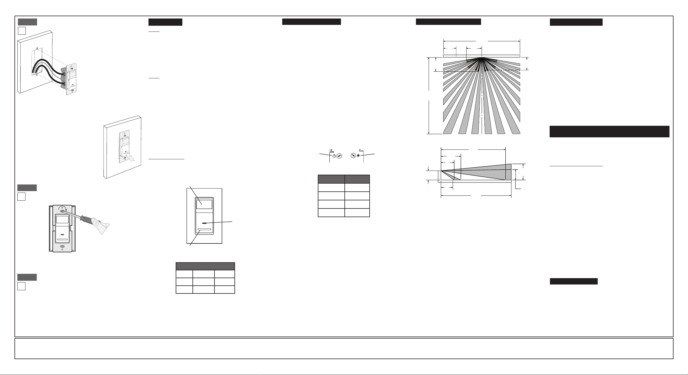
SENSING AREA COVERAGE
Field-of-View (Horizontal)
Side (Vertical) Field-of-View
1.5m
5ft
30ft
9.1m
30ft
9.1m
6ft
1.7m
1.8m
6ft
5ft
1.5m
30ft
9.1m
1.4m
4ft
8.4m
27ft
2.1m
7ft
1.5m
5ft
1.2m
4ft
1.7m
6ft
2.6m
8ft
Locator
Light
Lens
FCC COMPLIANCE STATEMENT
ThisdevicecomplieswithPart15oftheFCCRules.Operationissubjectto
followingtwoconditions:(1)thisdevicemaynotcauseharmfulinterference,
and(2)thisdevicemustacceptanyinterferencereceived,including
interferencethatmaycauseundesiredoperationofthedevice.
Thisequipmenthasbeentestedandfoundtocomplywiththelimitsfora
ClassBDigitalDevice,pursuanttoPart15oftheFCCRules.Theselimits
aredesignedtoprovidereasonableprotectionagainstharmfulinterference
inaresidentialinstallation.Thisequipmentgenerates,uses,andcanradiate
radiofrequencyenergyand,ifnotinstalledandusedinaccordancewith
theinstructions,maycauseharmfulinterferencetoradiocommunications.
However,thereisnoguaranteethatinterferencewillnotoccurinaparticular
installation.Ifthisequipmentdoescauseharmfulinterferencetoradioor
televisionreception,whichcanbedeterminedbyturningtheequipmentOFF
andON,theuserisencouragedtotrytocorrecttheinterferencebyoneor
moreofthefollowingmeasures:
•ReorientorrelocatethereceivingAntenna.
•Increasetheseparationbetweentheequipmentandthereceiver.
•Connecttheequipmentintoanoutletonacircuitdifferentfromthatto
whichthereceiverisconnected.
•Consultthedealeroranexperiencedradio/tvtechnicianforhelp.
FCC CAUTION
AnychangesormodicationsnotexpresslyapprovedbyLeviton
ManufacturingCo.,Inc.,couldvoidtheuser'sauthoritytooperatethe
equipment.
NOTE: TooperatetheIPS06asavacancysensor(manualON/Auto
OFF)-rotatethelightleveladjustmentfullycounterclockwise.
FOR CANADA ONLY
Forwarrantyinformationand/orproductreturns,residents
ofCanadashouldcontactLevitoninwritingatLeviton
Manufacturing of Canada Ltd to the attention of the Quality
Assurance Department, 165 Hymus Blvd, Pointe-Claire
(Quebec), Canada H9R 1E9orbytelephoneat1 800 405-5320.

This manual suits for next models

1

Other Leviton Accessories manuals

Leviton MDS10-ID Series User manual

Leviton

Leviton MDS10-ID Series User manual

Leviton OSFHU-ITW User manual

Leviton

Leviton OSFHU-ITW User manual

Leviton 37820 User manual

Leviton

Leviton 37820 User manual

Leviton OPB15 User manual

Leviton

Leviton OPB15 User manual

Leviton 5207-S00 User manual

Leviton

Leviton 5207-S00 User manual

Leviton Provolt ODC04-IDW User manual

Leviton

Leviton Provolt ODC04-IDW User manual

Leviton WSWDR-H9W User manual

Leviton

Leviton WSWDR-H9W User manual

Leviton OSC20-M0W User manual

Leviton

Leviton OSC20-M0W User manual

Leviton 9864-LED User manual

Leviton

Leviton 9864-LED User manual

Leviton GreenMax OSR05-IC Series User manual

Leviton

Leviton GreenMax OSR05-IC Series User manual

Leviton Decora ODS15-IDx User manual

Leviton

Leviton Decora ODS15-IDx User manual

Leviton Acenti QuickPort AC642 User manual

Leviton

Leviton Acenti QuickPort AC642 User manual

Leviton OSC10-U0W User manual

Leviton

Leviton OSC10-U0W User manual

Leviton OSFHU Operation manual

Leviton

Leviton OSFHU Operation manual

Leviton OSFHS-lxW User manual

Leviton

Leviton OSFHS-lxW User manual

Leviton OSFHU-CTW User manual

Leviton

Leviton OSFHU-CTW User manual

Leviton T5631 User manual

Leviton

Leviton T5631 User manual

Leviton OSS10-IDx User manual

Leviton

Leviton OSS10-IDx User manual

Leviton ODS10-ID Series User manual

Leviton

Leviton ODS10-ID Series User manual

Leviton WSCPC User manual

Leviton

Leviton WSCPC User manual

Leviton ODP10-I1W User manual

Leviton

Leviton ODP10-I1W User manual

Leviton Provolt ODC05-MDW User manual

Leviton

Leviton Provolt ODC05-MDW User manual

Leviton T6525 User manual

Leviton

Leviton T6525 User manual

Leviton 80301 User manual

Leviton

Leviton 80301 User manual

Popular Accessories manuals by other brands

Dragino LWL02 user manual

Dragino

Dragino LWL02 user manual

Danfoss 086U9563 installation instructions

Danfoss

Danfoss 086U9563 installation instructions

Baumer OADM 20I6480/S14F quick start guide

Baumer

Baumer OADM 20I6480/S14F quick start guide

Extollo LANSocket 1500 Product guide

Extollo

Extollo LANSocket 1500 Product guide

Melaleuca AROMATIC BLISS Instructions for use

Melaleuca

Melaleuca AROMATIC BLISS Instructions for use

Dometic REVO ZIP 200 Installation and operating manual

Dometic

Dometic REVO ZIP 200 Installation and operating manual

SkyLink PS-103 user manual

SkyLink

SkyLink PS-103 user manual

Honeywell DT6360STC installation instructions

Honeywell

Honeywell DT6360STC installation instructions

Major tech PIR33 instructions

Major tech

Major tech PIR33 instructions

ISHIDA WPL-3000 Service manual

ISHIDA

ISHIDA WPL-3000 Service manual

Aethra ISDN71 Technical specifications

Aethra

Aethra ISDN71 Technical specifications

Belleze 80QT owner's manual

Belleze

Belleze 80QT owner's manual

Ergon Performance Comfort Series Installation instructions & instructions for use

Ergon

Ergon Performance Comfort Series Installation instructions & instructions for use

Lithonia Lighting OFLR 9LN 120 MO BZ M2 operating instructions

Lithonia Lighting

Lithonia Lighting OFLR 9LN 120 MO BZ M2 operating instructions

Pepperl+Fuchs KVF-104-PF manual

Pepperl+Fuchs

Pepperl+Fuchs KVF-104-PF manual

VAF instruments Viscosense 3 Instructions for installation, operation care and maintenance

VAF instruments

VAF instruments Viscosense 3 Instructions for installation, operation care and maintenance

Summit Solo Deluxe manual

Summit

Summit Solo Deluxe manual

SEVERIN EM 3965 Dimensions

SEVERIN

SEVERIN EM 3965 Dimensions

manuals.online logo
manuals.online logoBrands
  • About & Mission
  • Contact us
  • Privacy Policy
  • Terms and Conditions

Copyright 2025 Manuals.Online. All Rights Reserved.