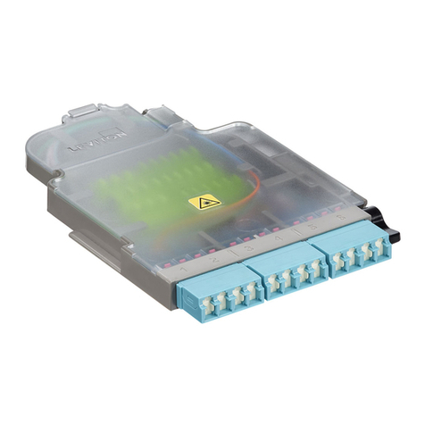
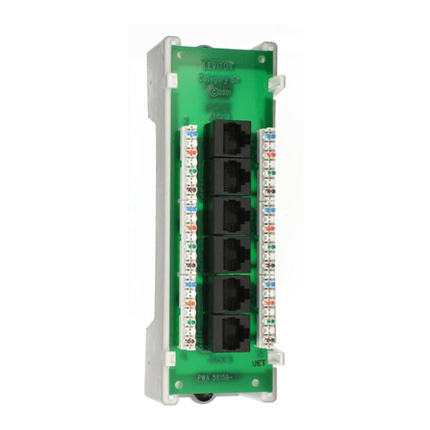
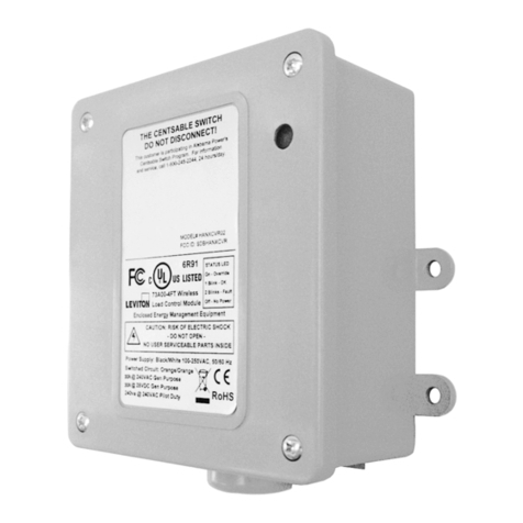
Leviton rMB81-001 Operation manual
Other Leviton Control Unit manuals
Leviton
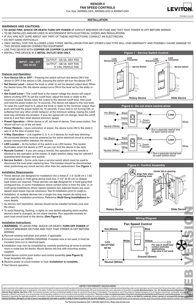
Leviton RENOIR II Series User manual
Leviton
Leviton UPB Mounting instructions

Leviton
Leviton 47603-ASO User manual
Leviton
Leviton VerifEye A8911 User manual
Leviton
Leviton Decora Smart DW15A Series User manual
Leviton
Leviton MC 7516 User manual
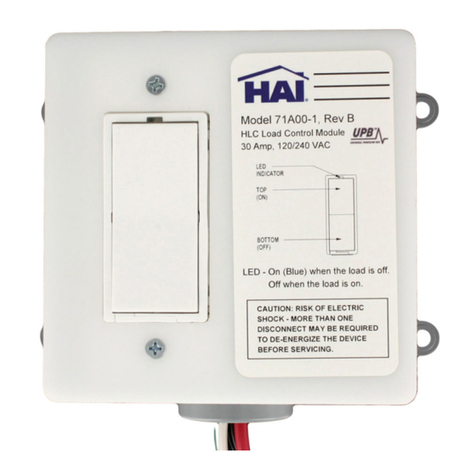
Leviton
Leviton 71I00-1 Mounting instructions

Leviton
Leviton 73A00-3ZB Mounting instructions
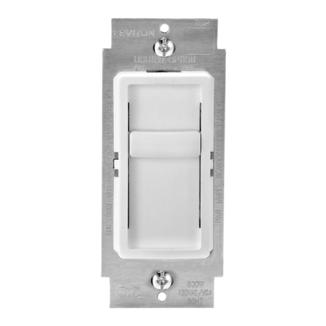
Leviton
Leviton SureSlide 6637 User manual

Leviton
Leviton GreenMAX RPM00-100 User manual

Leviton
Leviton 73A00-3ZB Mounting instructions
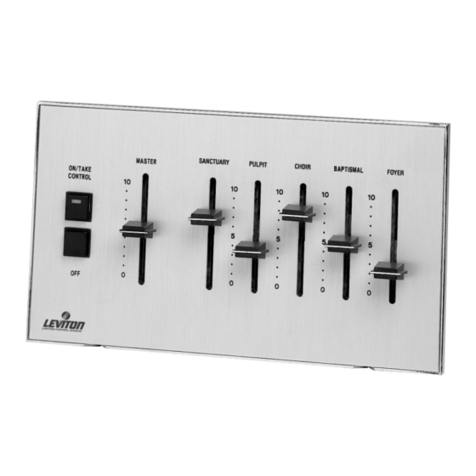
Leviton
Leviton CP series Operation manual

Leviton
Leviton 10A11-1 Mounting instructions
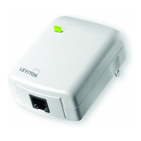
Leviton
Leviton VIZIA RF PLUS VRC0P-1LW User manual
Leviton
Leviton 47616-DSB User manual
Leviton
Leviton miniZ Series User manual

Leviton
Leviton LV200 User manual

Leviton
Leviton DOS02 User manual

Leviton
Leviton 476TL-T12 User manual
Leviton
Leviton decora 6630 User manual
Popular Control Unit manuals by other brands

Festo
Festo Compact Performance CP-FB6-E Brief description

Elo TouchSystems
Elo TouchSystems DMS-SA19P-EXTME Quick installation guide

JS Automation
JS Automation MPC3034A user manual

JAUDT
JAUDT SW GII 6406 Series Translation of the original operating instructions

Spektrum
Spektrum Air Module System manual

BOC Edwards
BOC Edwards Q Series instruction manual

KHADAS
KHADAS BT Magic quick start

Etherma
Etherma eNEXHO-IL Assembly and operating instructions

PMFoundations
PMFoundations Attenuverter Assembly guide

GEA
GEA VARIVENT Operating instruction

Walther Systemtechnik
Walther Systemtechnik VMS-05 Assembly instructions

Altronix
Altronix LINQ8PD Installation and programming manual
