1. Press the power button on the Touch Control
2. Selected zone button
3. Press Dynamic mode button to select preferred scene
(10 options see Fig.4.)
4. Press or to adjust speed of selected scene
5. Repeat steps 2, 3 and 4 to set scenes for zones and
(note: brightness is not adjustable in dynamic mode)
JCC Lighting Products Ltd. Innovation Centre Beeding Close Southern Cross Trading Estate Bognor Regis West Sussex PO22 9TS Technical Support: 01243 838986 Customer Services: 01243 838999
Commissioning the Hand Held Remote Control JC121371
Installing the Controller JC121372
To t battery ( 1 x 3V CR2032 not supplied), remove the cover on the back of the control, t battery and then ret cover.
1. Connect the 24VDC output from the non-dimmable driver to the input on the controller
using DC cable or the DC jack plug(not supplied) as illustrated in Fig.1.
2. Connect the RGBW strip to the Controller output as illustrated in Fig.2.
RGBW connection Key:
V+=(Black)
R =(RED)
G =(GREEN)
B =(BLUE)
W=(WHITE)
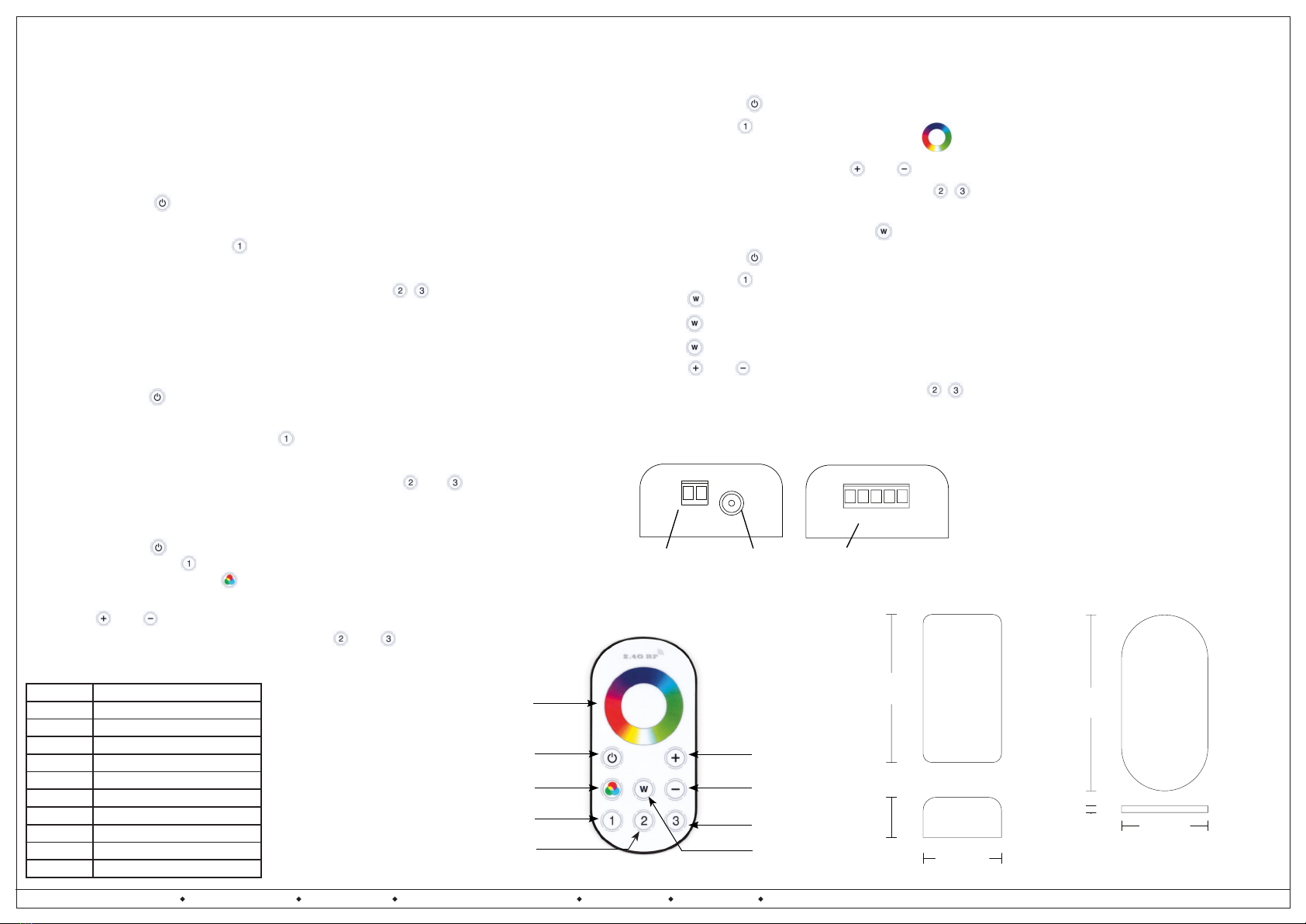
Fig.1.
DC Power input port 1
(jack plug-not supplied)
DC Power input
port 2(Cable)
RGBW output
connections
- + V+ R G B W
Fig.2.
Fig.4.
Number Mode
1 RGB jumping change
2 RGB fade in/out
3 7 colour jumping change
4 7 colour strobe
5 White fade in/out
6Red fade in/out + ash 3 times
7Green fade in/out + ash 3 times
8Blue fade in/out + ash 3 times
9White fade in/out + ash 3 times
10 Automatic cycle
Controller dimensions
0
4.0
Remote Control dimensions
Scene setting -manual selection colours
1. Press the power button on the Remote Control
2. Selected zone button
3. Touch colour wheel to select preferred colour
4. Touch to adjust brightness press or button
5. Repeat steps 2, 3 and 4 to set scenes for zones
(note: speed is not adjustable in this mode)
Scene setting - manual selection button
1. Press the power button on the Remote Control
2. Selected zone button
3. Press button once will select RGB and white LEDs together
4. Press button again to turn off white LED’s
5. Press button and hold for 1 sec to turn off RGB and turn on white LEDs
6. Press or to adjust brightness
7. Repeat steps 2, 3 and 4 to set scenes for zones
(note: speed is not adjustable in this mode)
Hand Held Remote Control Reset(Fig.3.)
1. Press the power button on the Remote Control
2. Turn on mains supply to selected group(zone)
3. Press and hold selected “Zone” button for 2 to 8 seconds
4. Unpairing is completed when the white LED’s Flash 9 times
5. Repeat steps 2, 3 and 4 to unpair additional groups to zones and
Hand Held Remote Control pairing set up(Fig.3.)
1. Press the Power button on the Remote Control
2. Turn on mains supply to selected group(zone)
3. Press and hold “Zone” button for 2 to 8 seconds
4. Pairing is completed when the white LED’s Flash 3 times
5. Repeat steps 2, 3 and 4 to pair additional groups to zones
Note: The maximum number of hand held remotes that can be paired to a group of
controllers is two, to pair the second hand held remote, repeat steps 1 through to 5
Scene setting -Dynamic mode
Fig.3.
Dynamic mode
Zone 1 button
Power button
Colour wheel
Speed/Brighness +
Speed/Brighness -
Zone 3 button
“W” function button
Zone 2 button


