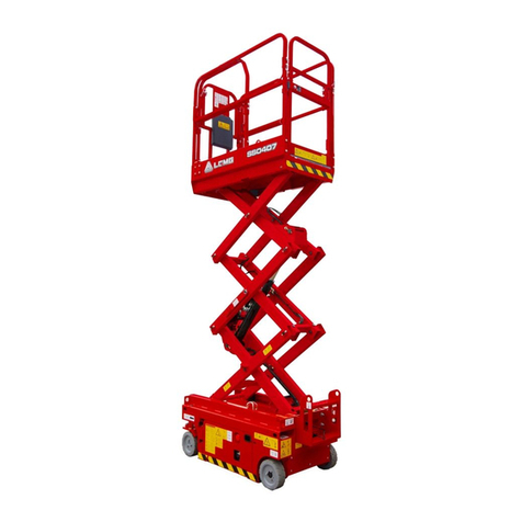
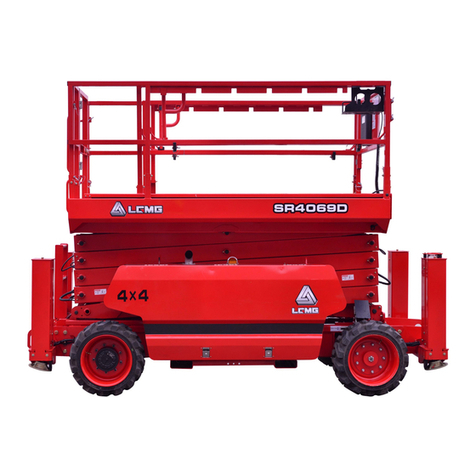
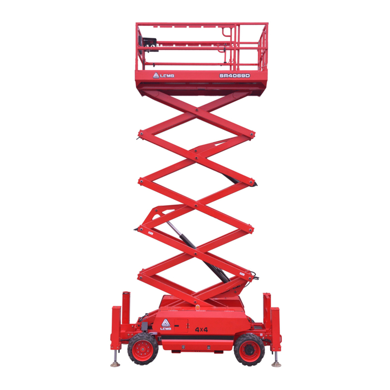
LGMG SR3369E User manual

LGMG North America Inc.
Maintenance Manual
SR3369E/SR4069E
Mobile Elevating Work Platform
ANSI
!
WARNING
Before operation and maintenance, the
drivers and service personnel shall
always read and thoroughly understand
all information in this manual. Failure to
do so may result in, fatal accidents or
personal injury.
This manual must be kept with this
machine at all times.

This page left blank intentionally

LGMG North America Inc. Maintenance Manual
II
Contents
Foreword...................................................................................................III
Safety Precautions..................................................................................IV
Chapter 1 Maintenance.............................................................................1
1.1 Compliance....................................................................................... 3
1.2 Checking the Safety Manual............................................................. 3
1.3 Checking the labels and signs.......................................................... 3
1.4 Checking for damaged, loose or missing parts ................................. 3
1.5 Checking the wires ........................................................................... 4
1.6 Checking the battery......................................................................... 4
1.7 Checking the electrical contactors .................................................... 5
1.8 Checking the tires and wheels.......................................................... 5
1.9 Checking the hydraulic tank vent cap ............................................... 6
1.10 Checking the leakage of hydraulic oil.............................................. 6
1.11 Checking the hydraulic filter............................................................ 6
1.12 Replacing the hydraulic tank air filter .............................................. 7
1.13 Checking the hydraulic oil level....................................................... 7
1.14 Checking or changing the hydraulic oil............................................ 8
1.15 Checking the oil level in the reducer ............................................... 8
1.16 Replacing the reducer gear oil........................................................ 9
1.17 Checking or replacing the scissor arm slide block........................... 9
1.18 Regular maintenance...................................................................... 9
Chapter 2 Schematic Diagram................................................................11

LGMG North America Inc. Maintenance Manual
III
Foreword
Thank you for choosing to use this Mobile Elevating Work Platform from LGMG North America. This
machine is designed according to A92.20-2018.The information specified in this manual is intended for
the safe and proper operation of this machine for its’ intended purpose.
For maximum performance and utilization of this machine, thoroughly read and understand all the
information in this manual before starting, operating, or performing maintenance on this machine.
Due to continuous product improvements, LGMG North America reserves the right to make specification
changes without any prior notifications. For any updated information, contact LGMG NorthAmerica.
Ensure all preventive maintenance to the machine is performed according to the interval specified in the
maintenance schedule.
Keep this manual with this machine for reference at all times. When the ownership of this machine is
transferred, this manual shall be transferred with this machine. This manual must be replaced
immediately if it is lost, damaged, or becomes illegible.
This manual is copyrighted material. The reproduction or copy of this manual is not allowed without the
written approval of LGMG North America.
The information, technical specifications and drawings in this manual are the latest available when this
manual is issued. Due to continuous improvement, LGMG North America reserves the right to change
the technical specifications and machine design without notice. If any specifications and information in
the manual are not consistent with your machine, please contact the service department of LGMG North
America.
△
! WARNING
Only personnel who have been properly trained and qualified to operate or
maintain this machine can operate, repair and maintain this machine.
Improper operation, maintenance, and repair are dangerous and can cause
personal injury and death.
Before any operation or maintenance, the operator shall thoroughly read this
manual. Do not operate, perform any maintenance or make any repairs on this
machine before reading and understanding this manual.
The user shall load the platform strictly according to the load rating of the
platform. Do not overload the platform or make any modifications to the platform
without permission from LGMG North America.
The operation regulations and preventions in this manual are only applicable for
the specified use of this machine.

LGMG North America Inc. Maintenance Manual
IV
Safety Precautions
The operator of this machine shall understand and follow the existing safety regulations of state and
local governments. If these are unavailable, the safety instructions in this manual shall be followed.
To help prevent accidents, read and understand all warnings and precautions in this manual before
operation or performing maintenance.
It is impossible to foresee every possible hazard and the safety instructions in this manual may not cover
all safety prevention measures. Always ensure the safety of all personnel and protect the machine
against any damage. If unable to confirm the safety of some operations, contact LGMG North America.
The operation & maintenance prevention measures listed in this manual are only applicable to the
specified uses of this machine. LGMG North America assumes no responsibility if this machine is used
beyond the range of this manual. The user and the operator shall be responsible for the safety of such
operations.
Do not perform any operation forbidden in this manual in any situation.
The following signal words are applicable for identifying the level of safety information in this manual.
△
! Danger:
An imminent situation, that if not avoided, will result in severe injuries or death. This
is also applicable to situations that will cause serious machine damage, if not
avoided.
△
! Warning:
A potentially dangerous situation, that if not avoided, may result in severe injuries or
death. This is also applicable to situations that may cause serious machine damage,
if not avoided.
△
! Notice:
A situation, that if not avoided, may result in minor or intermediate injury. This is also
applicable to situations that may cause machine damage or shorten machine service
life.

LGMG North America Inc. Maintenance Manual
1
Chapter 1 Maintenance

LGMG North America Inc. Maintenance Manual
2

LGMG North America Inc. Maintenance Manual
3
1.1 Compliance
1) The operator can only perform routine
maintenance items as specified in this manual.
2) Regular maintenance inspections should
be performed by trained service technicians as
required by the manufacturer
Maintenance symbol legend
The following symbols appear in this manual to
indicate the relevant meaning in the operation
instructions. When one or more symbols appear
in front of the maintenance procedure, the
meanings expressed are as follows.
It indicates that a tool is required to
perform this procedure.
It indicates that a new part is
required to perform this procedure.
It indicates that the engine must be
cooled before performing this
procedure
1.2 Checking the Safety
Manual
It is necessary for safe equipment operation to
keep the Operator and Safety Manual in good
condition. The manual and each equipment
should be stored in a container provided on the
work platform. An illegible or missing manual
will not provide the necessary safety and
operation information for safe operation.
1) Check that the storage container is on site
and in good condition.
2) Check that the Operator, Responsibility,
and Safety Manual is complete in the
storage container on the work platform.
3) Check that each page of the manual is
identifiable and in good condition.
4) Put the manual in the storage file box after
use.
△
! If you need to replace the manual,
please contact the company’s service
personnel.
1.3 Checking the labels and
signs
It is necessary for safe operating equipment to
keep all safety and instructions labels and signs
in good conditions. Labels are used to remind
operators and staff of the possible hazards
when operating this equipment. User operation
and maintenance information is also provided.
An illegible label does not remind the staff of
steps or hazards, and may also result in unsafe
operating conditions.
Refer to the label section in this manual and use
the label menu and instructions to check
whether all labels are in place.
Check all the labels for clarity and damage and
immediately replace any damaged or illegible
ones.
△
!If you want to replace the label,
please contact the company’s service
personnel.
1.4 Checking for damaged,
loose or missing parts
This check should be performed every 8 h or
every day.
Daily equipment status checks are necessary
for safe equipment operation and good
equipment performance. Incorrect location and
repair damage, and loose or missing parts may
result in unsafe operating conditions.
1) Check the entire equipment for damage
and incorrect installation or loss of parts,
including:
Electrical components, wires and cables

LGMG North America Inc. Maintenance Manual
4
Hydraulic hoses, joints, valve blocks,
hydraulic cylinders
Hydraulic tank
Wear pad
Tire and wheel
Limit switch, horn
Nuts, bolts and other fasteners
Platform extension
Platform entry port
Indicators and alarms
Safety arm
Scissor arm pins and fasteners
Platform control handle
outrigger cover and foot pad
Check the entire machine for:
Crack in the weld or structural member
Check the platform, frame and chassis for
deformation or open welding
Dent or damage to the machine
Make sure all structural members and other
critical components are complete, and all
associated fasteners and pins are in the
right position and tightened
The platform guide rail has been installed,
the platform guide rail bolts are in place and
the bolts are properly tightened.
△
!Caution: If the platform must be lifted
to check the machine, make sure the safety
arm is in the right position. See the
"Operating Instruction" section.
1.5 Checking the wires
1) This check should be performed every 250
h or quarterly, whichever comes first.
2) It is important for safe operation and good
machine performance to keep the wires in
good conditions. Failure to find and replace
the burn-out, scratched, corroded or bent
wires will result in unsafe operating
conditions and damage to the parts.
Risk of electric shock/explosion
Contact with live circuits may cause serious
injury or death. Do not wear rings, watches or
other jewelry.
1) Check if the ground wire under the chassis
is missing or damaged.
2) Check the following areas for burn-out,
scratched, corroded, bent or loose wires:
Rear axle: Drive motor, limit switch
Tank side: Ground control unit inside, wire
harness connection, motor control unit,
battery charger
Battery side: Battery, fuse
Machine: Platform, platform control unit,
wire harness connection
3) Check whether all wire harness connectors
are coated with insulating grease:
Ground control unit
Platform control unit
Motor Control unit
Valve component
Limit switch
Sensor
1.6 Checking the battery
Good battery condition is critical to normal

LGMG North America Inc. Maintenance Manual
5
machine performance and safe operation.
Improper electrolyte levels or damaged cables
and wires may result in component damage and
dangerous situations.
△
!Caution: This check is not
required for machines that are
equipped with sealed or
maintenance-free batteries.
△
!Warning: Risk of electric shock.
Contact with an electrical circuit may
result in death or serious personal
injury. Remove all rings, watches or
other accessories.
△
!Warning: Risk of body injury. The
battery contains acidic substances.
Avoid spilling or touching the acid in
the battery. Soda and water can be
used to neutralize the overflowing
battery acid.
△
!Caution: This check should be
performed after the battery is fully
charged.
1) Wear protective clothing and goggles.
2) Make sure the battery cable is securely
wired and not corroded.
3) Make sure the battery lock bracket is
stable.
4) Remove the battery vent cap.
5) Check the battery acid level. If necessary,
fill the distilled water through a filling pipe at
the bottom of the battery. Do not add
excessive distilled water.
6) Install the vent cap.
△
!Caution: Adding a terminal
protector and an anti-corrosion sealant
can help eliminate the corrosion on the
battery terminals and cables.
1.7 Checking the electrical
contactors
This check should be performed every 250 h or
quarterly, whichever comes first.
It is important for safe operation of the machine
to keep the electrical contactor in good condition.
Failure to find the worn or damaged contactors
in a timely manner may endanger the work
conditions and cause component damage.
1)Open the battery side cover.
2)Visually check the following aspects of the
contactor:
Transitional burning
Transitional bending
Transitional pitting
△
!Warning: Risk of motor burn-out.
Contact with an electrical circuit may
result in death or serious personal
injury. Remove all rings, watches or
other accessories.
△
!Caution: In the event of any
damage, the contactor should be
replaced.
1.8 Checking the tires and
wheels
This check should be performed every 250 h or
quarterly, whichever comes first.
It is important for safe operation and good
performance to keep the tires and wheels in
good conditions. Failure of the tires and wheels
may cause the machine to roll over. Failure of
finding and repairing the problem in time may
cause damage to the machine.

LGMG North America Inc. Maintenance Manual
6
1)Check the tire treads and sides for
scratches, cracks, punctures or other
abnormal wear.
2)Check the wheels for damage, bending or
cracking.
1.9 Checking the hydraulic
tank vent cap
1) This check should be performed every 8 h
or every day, whichever comes first.
2) An unobstructed hydraulic tank cover is
essential for good mechanical performance and
long service life. A dirty or clogged vent cap may
cause poor machine performance. Frequent
checks should be performed under the harsh
working environment.
①Remove the vent cap from the hydraulic
tank cover.
②Check the ventilation condition.
Result: Air can pass through the vent cap.
Result: If the air fails to pass through the vent
cap, clean or replace it. Proceed with step 3.
Note: When checking the tank cover for
ventilation, the air should pass freely.
3) Carefully clean the tank vent cap with a
mild solvent and dry it with low pressure
compressed air. Repeat step 2.
4) Install the hydraulic tank vent cap.
1.10 Checking the leakage of
hydraulic oil
Check for leakage every 8 h or every day.
△
!Risk of personal injury. Leaking
hydraulic oil under pressure can pierce
or burn skin.
1) Check the hydraulic oil sediments, oil drops
or oil residue in the following areas.
All hydraulic cylinders
All valve elements
All pipes and fittings
Reducer
Filter
Hydraulic tank
Hydraulic pump
Under the chassis
Axle
The ground area under the equipment.
1.11 Checking the hydraulic
filter
It should be checked or replaced every 500 h or
quarterly.
△
!If the working environment is
dusty, this check should be performed
more frequently.
Replacing the hydraulic filter is necessary to
maintain good machine performance and long
service life. A dirty or clogged filter may cause
the machine performance degradation, and
continuous operation may result in component
damage. The filter should be replaced more
frequently in extremely dirty working conditions.
△
!Risk of personal injury. Be careful
of hot oil. Exposure to hot oil may
cause severe burns.
△
!This step should be performed
when the machine is stopped.
Replace the hydraulic tank return filter
1) This step should be performed every 500 h
or annually, whichever comes first.

LGMG North America Inc. Maintenance Manual
7
2) Replacing the return filter is essential for
good performance and service life of the
machine. A dirty or clogged filter may affect
the machine performance and continued
operation may result in parts damage. The
filter element should be replaced more
frequently in harsh working conditions.
Caution: Risk of burn
Be careful of hot oil. Exposure to hot oil may
cause severe burns.
①Remove the filter with a wrench. Clean the
area of contact between the hydraulic filter and
the filter head.
②Apply a thin layer of new oil to the gasket of
the new hydraulic filter.
③Install a new filter and tighten it.
④Record the date of replacement on the filter
with a marker.
⑤Remove all traces of oil spilled in the
replacement process.
⑥Turn the key switch to the ground control
unit and pull out the red emergency stop buttons
on the ground and platform control units.
⑦Press the lift function button.
⑧Check the filter components for oil leakage.
1.12 Replacing the hydraulic
tank air filter
It should be replaced every 500 h or quarterly,
and should be replaced more frequently in the
dusty working environment.
△
!This step should be performed
when the machine is stopped.
1)Remove the filter element.
2)Clean the inside of the cylinder and the end
cap with a wet cloth.
3)Install a new air filter element.
1.13 Checking the hydraulic
oil level
It should be checked every 8 h or every day.
Maintaining the hydraulic fluid at the proper oil
level is essential for machine operation. If the
hydraulic oil is at an unsuitable oil level, the
hydraulic components may be damaged.
Through daily inspections, the inspector can
determine changes in the hydraulic oil level
which can indicate problems with the hydraulic
system.
△
!Caution: This step should be
performed when the platform is in the
retracted state and the machine is
stopped.
1) Park the equipment on a flat surface. The
platform is in the retracted state.
2) Check the oil mark on the hydraulic tank.
When the frame is in the retracted state, the
hydraulic oil level should be located at
1/3~2/3 of the level gauge. If necessary, fill
the hydraulic oil.
Hydraulic oil specification
Hydraulic oil type
46#

LGMG North America Inc. Maintenance Manual
8
1.14 Checking or changing
the hydraulic oil
The hydraulic oil should be changed every 500
h or quarterly.
△
!If the hydraulic oil is not changed
during the two-year inspection, it
should be checked quarterly. The
hydraulic oil should be changed when
it is found unqualified after checking.
△
!This step should be performed
when the frame is in the retracted
position.
△
!When removing the hose
assembly or fitting, the O-ring or hose
end on the fitting must be replaced and
tightened to the specified torque
during installation.
1)Press the red “Emergency Stop” button to
the “OFF” position.
2)Place a suitable container under the
hydraulic tank.
3)Remove the drain plug on the hydraulic
tank and drain the tank completely.
△
!Warning: Risk of body injury. The
sprayed hydraulic oil may penetrate
and burn the skin. Slowly loosen the
hydraulic connections to gradually
reduce the oil pressure. Prevent
hydraulic oil for spraying.
4)Mark, disconnect and plug the suction hose
on the hydraulic tank. Cover the pipe fitting.
5)Mark, disconnect and plug the return hose
on the return filter. Cover the filter
connector.
6) Remove the return filter and filter head
component. Cover and plug the connector.
7) Remove the hydraulic tank from the
machine.
8) Remove the inlet filter and clean it with a
neutral solvent or replace it.
9) Clean the inner surface of the hydraulic
tank with a neutral solvent.
10) Install the oil drain plug.
11) Install the hydraulic tank to the machine.
12) Install the hose.
13) Fill the hydraulic oil to the hydraulic tank
until the liquid level is 1/3~2/3 of the
observation meter. No overflow is allowed.
14) Wipe off the hydraulic oil that may have
spilled.
15) Check all the functions of the machine
through a full cycle and check for oil
leakage.
16) Recheck the tank level after a cycle and
refill to 1/3~2/3.
1.15 Checking the oil level in
the reducer
This step should be performed every 250 h or
quarterly.
Incorrect oil level in the reducer may result in
performance degradation and continuous
operation may result in component damage.
1) Rotate the drive unit until one plug is at the

LGMG North America Inc. Maintenance Manual
9
highest position and has an angle of 90
degrees with the other plug.
2) Remove the other plug and check the oil
level.
Result: The oil level should be the same as the
bottom of the side plug hole.
3) When necessary, remove the upper plug
and fill the oil until the oil level is the same
as the bottom of the side plug hole.
4) Apply the pipe thread sealant to the plug
and install the plug in the reducer.
5) Repeat this step for each reducer.
Oil specification
80-90/W
Capacity
0.68L (each reducer)
1.16 Replacing the reducer
gear oil
The first maintenance should be performed after
50 h, and the second maintenance should be
performed at an interval of 1000 h or annually.
Changing the gear oil of the under is necessary
to maintain good equipment performance and
long service life. Failure to change the gear oil
each year may result in performance
degradation and continuous operation may
result in component damage.
1) Select the reducer to be serviced and drive
the equipment till one of the two plugs is at
the lowest point.
2) Remove the two plugs and drain the oil
completely in a suitable container.
3) Rotate the drive unit until one plug is at the
highest position and has an angle of 90
degrees with the other plug.
4) Fill the oil from the reducer’s filler hole at a
high point till the oil level is the same as that
in the side hole at the bottom. Install the
plug.
5) Repeat this step for oil filling of each
reducer.
Oil specification
80-90/W
Capacity
0.68L (each reducer)
1.17 Checking or replacing
the scissor arm slide block
This step should be performed every 1000 h or
annually, whichever comes first.
1) The quality of the scissor arm slide block is
critical to the safe operation of the machine.
A worn slide block may result in component
damage and unsafe working problems.
2) The wear pad should be performed the
platform is retracted.
①Measure the height of the wear pads on the
chassis and platform rails.
Result: The measurement result is less than 8
mm. Replace the slide block.
②Apply lubricant between the chassis rail
and slide block, platform rail and slide block.
1.18 Regular maintenance
Maintenance work on a quarterly, annual and
biennial basis must be performed by those who
are trained and qualified in the machine

LGMG North America Inc. Maintenance Manual
10
maintenance according to the procedures
specified in the maintenance manual.
For a machine that has been idle for more than
three months, it must be checked quarterly
before it is put into operation again.

LGMG North America Inc. Maintenance Manual
11
Chapter 2 Schematic Diagram

LGMG North America Inc. Maintenance Manual
12

LGMG North America Inc. Maintenance Manual
13
Electrical schematic diagram

LGMG North America Inc.LMaintenance Manual
14
Hydraulic schematic diagram

15
Other manuals for SR3369E
2
This manual suits for next models
1
Table of contents
Other LGMG Lifting System manuals
Popular Lifting System manuals by other brands

Smiley Lifting Solutions
Smiley Lifting Solutions SPYDERCRANE URW094 Operator's reference guide

rav
rav KPH 370.40EX Translation of the original instructions

Atlas Equipment
Atlas Equipment 90HSC Installation & operation manual

Genie
Genie Z-80/60 Operator's manual

Dhollandia
Dhollandia DH-LSP Mounting instructions

SKF
SKF Telemag TFG 5 Installation, operation and maintenance manual