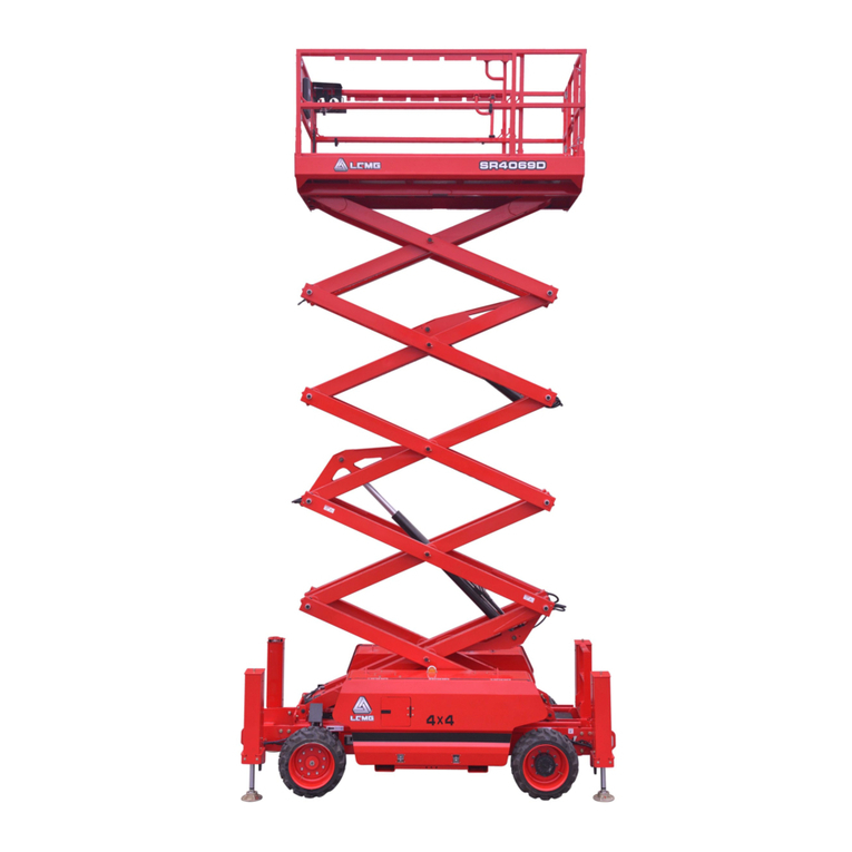
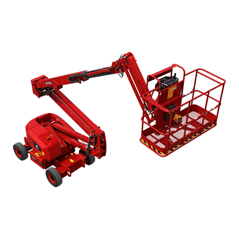
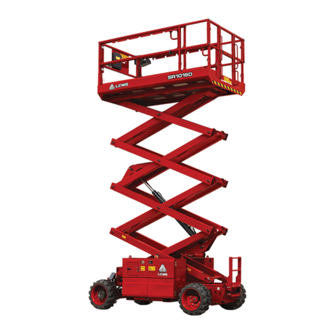
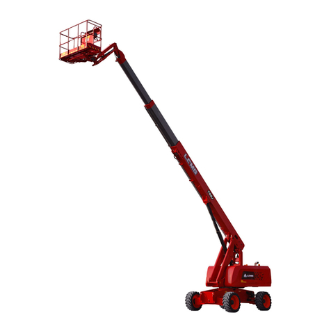
LGMG AR65J User manual

LGMG North America Inc.
Maintenance Manual
AR65J
Articulated Boom
Mobile Elevating Work Platform
ANSI
△! WARNING
Before operation and maintenance,
the drivers and service personnel
shall always read and thoroughly
understand all information in this
manual. Failure to do so may result in,
fatal accidents or personal injury.
This manual must be kept with
this machine at all times.
This page left blank intentionally
LGMG North America Inc. Maintenance Manual
Contents
Foreword.....................................................................................................II
Safety Notices............................................................................................III
Chapter 1 Maintenance...............................................................................1
1.1 Observing the Regulations................................................................ 3
1.2 Inspection Manual............................................................................. 3
1.3 Check Labels and Decals ................................................................. 3

1.4 Every Day or Every 8 Hours ............................................................. 3
1.5 Every 100 Hours............................................................................... 7
1.6 Every 250 Hours............................................................................... 8
1.7 Every 400 Hours............................................................................. 14
1.8 Every 500 Hours............................................................................. 17
1.9 Every 1000 Hours ........................................................................... 22
1.10 Every 2000 Hours ......................................................................... 24
1.11 Scheduled maintenance................................................................ 26
1.12 Engine Fault Table ........................................................................ 27
1.13 Engine fault codes ........................................................................ 32
1.14 Maintenance Point........................................................................ 40
Chapter 2 Schematic Diagram ..................................................................47
I
LGMG North America Inc. Maintenance Manual Foreword
Thank you for choosing to use this Mobile Elevating Work Platform from LGMG North America. This
machine is designed according to ANSI A92.20-21 and CSA B354.6-17. The information specified in this
manual is intended for the safe and proper operation of this machine for its’ intended purpose.
For maximum performance and utilization of this machine, thoroughly read and understand all the
information in this manual before starting, operating, or performing maintenance on this machine.
Due to continuous product improvements, LGMG North America reserves the right to make specification
changes without any prior notifications. For any updated information, contact LGMG North America.
Ensure all preventive maintenance to the machine is performed according to the interval specified in the
maintenance schedule.
Keep this manual with this machine for reference at all times. When the ownership of this machine is

transferred, this manual shall be transferred with this machine. This manual must be replaced immediately
if it is lost, damaged, or becomes illegible.
This manual is copyrighted material. The reproduction or copy of this manual is not allowed without the
written approval of LGMG North America.
The information, technical specifications and drawings in this manual are the latest available
when this manual is issued. Due to continuous improvement, LGMG North America reserves
the right to change the technical specifications and machine design without notice. If any
specifications and information in the manual are not consistent with your machine, contact
the service department of LGMG North America
△! WARNING
Operators and maintenance personnel must read, understand and abide by the
safety regulations and operating instructions specified in this manual before
operating and maintaining this machine, otherwise, it may lead to casualties! Only
specially trained and qualified personnel can operate, maintain and repair the
machine.
Improper operation, maintenance and repair are dangerous and may result in
injury or death.
Users shall be familiar with the rated load, and overloading is strictly prohibited. The
users shall be responsible for all the consequences caused by overloading or
unauthorized modification.
The operating procedures and precautions provided in this manual are only
applicable to the specified purposes of this machine. If it is used for operations other
than those specified but not prohibited, make sure that there is no potential safety
hazard.
All dealers, owners, users, operators, lessors, lessees, and brokers must comply
with appropriate section(s) of applicable A92 standards.
II
LGMG North America Inc. Maintenance Manual
Safety Notices
The operator of this machine shall understand and follow the existing safety regulations of state and
local governments. If these are unavailable, the safety instructions in this manual shall be followed.
To help prevent accidents, read and understand all warnings and precautions in this manual before
operation or performing maintenance.
The safety measures are specified in Chapter 1 Safety.
It is impossible to foresee every possible hazard and the safety instructions in this manual may not cover
all safety prevention measures. Always ensure the safety of all personnel and protect the machine against
any damage. If unable to confirm the safety of some operations, contact LGMG North America.
The operation & maintenance prevention measures listed in this manual are only applicable to the

specified uses of this machine. LGMG North America assumes no responsibility if this machine is used
beyond the range of this manual. The user and the operator shall be responsible for the safety of such
operations.
Do not perform any operation forbidden in this manual in any situation.
The following signal words are applicable for identifying the level of safety information in this manual.
△! DANGER:
An imminent situation, that if not avoided, will result in severe injuries or death. This
is also applicable to situations that will cause serious machine damage, if not
avoided.
△! WARNING:
A potentially dangerous situation, that if not avoided, may result in severe injuries or
death. This is also applicable to situations that may cause serious machine damage,
if not avoided.
△! NOTICE:
A situation, that if not avoided, may result in minor or intermediate injury. This is also
applicable to situations that may cause machine damage or shorten machine service
life.
III
LGMG North America Inc. Maintenance Manual IV

LGMG North America Inc. Maintenance Manual
Chapter 1 Maintenance
1

LGMG North America Inc. Maintenance Manual 2
LGMG North America Inc. Maintenance Manual
1.1 Observing the
Regulations
1) You are properly trained and qualified to
operate and maintain the machine safely.
2) All safety regulations in this manual,
workplace safety regulations and applicable
government laws and regulations must be
read, understood and complied.
3) Equipped with PPE, such as helmet, seat
belt, safety shoes, goggles, protective clothing,
insulating gloves, insulating shoes, etc., and in
good physical condition.
4) When maintenance and repair procedures are
being performed, many dangers indicated in
the Operation Manual will also become
potential safety hazards.
5) Scheduled maintenance and repair can only
be completed by trained and qualified
maintenance technician.
6) Dispose of waste materials in accordance with
government regulations and workplace
regulations.
7) Only parts and consumables approved by
the LGMG can be used.
8) Always perform functional tests after
maintenance.
1.2 Inspection Manual
It's necessary for safe equipment operation to
keep operation manual and maintenance
manual in good condition. An illegible or missing
manual will not provide the necessary safety and
operational information for the safe operation.
1) Make sure that the operation manual and
maintenance manual are complete in the file
box.
2) Check each page of the inspection manual to
ensure that it is legible and in good
condition.
3) Put the manual into the file box after use.
△! CAUTION: If the manual needs to
be replaced, please contact the LGMG
service personnel.
1.3 Check Labels and Decals
It is necessary for safe operation of equipment to
keep all safety and description labels and decals

in good condition. The label warns the operator
and staff of many possible hazards during use of
this equipment. It also provides the user with
operation and maintenance information. The
illegible label cannot warn the staff of steps or
dangers, which may also lead to unsafe
operation.
Refer to the label section of this operation
manual to check whether all label are where they
shall be.
Check the clarity and damage of all label and
immediately replace any damaged or illegible
label.
△! CAUTION: If you need to replace
the label, please contact the LGMG
service personnel.
1.4 Every Day or Every 8
Hours
1.4.1 Check for Damaged and Loose or
Missing Part
Perform this step every 8 hours or every day.
Daily equipment status checks will be necessary
for safe equipment operation and good
equipment performance. Incorrect positioning
and repair damage, and loose or missing parts
may lead to unsafe operating conditions.
1) Check the damage of the whole equipment
and incorrect installation or loss of parts,
including:
●Electrical components, wiring and cable ●
Hydraulic hose, joint, valve block, hydraulic
3
LGMG North America Inc. Maintenance Manual
cylinder
●Fuel and hydraulic tank
●Sliders
●Tires and hubs
●Engine and related components
●Limit switches, horns
●Nuts, bolts and other fasteners
●Indicator lamps and alarms
●Drive shafts
Check the entire machine to find:
●Cracks in weld or structural parts
●Whether the chassis is deformed or open
weld
●Dent or damage to the machine
●Ensure that all structural parts and other key
components are complete and all relevant
fastener and pin are in the correct position
and tightened
Scheduled maintenance
In extremely cold, dusty or humid working
environment, more frequent lubrication and
maintenance than specified in "scheduled
maintenance" is required. During maintenance,
the maintenance items listed in the original
requirements shall be repeated.
For example, when proceeding the maintenance
item for 500 working hours, the maintenance
items listed for every 250 working hours and
every 100 working hours shall be carried out at
the same time.
1.4.2 Check the Hydraulic Oil Level and
Hydraulic Oil Leaks
Check the hydraulic oil level every 8 hours or
every day.
△! CAUTION: Perform this step
when the arm rod is in the stowed
position.

●Park the machine on a flat ground. The arm
rod shall retract to the stowed position.
Figure 1-1 Hydraulic oil dipstick
●Check the oil dipstick on the hydraulic oil tank.
The liquid level shall be within the M range
as shown in Figure 1-1. If the liquid level is
lower than M, the hydraulic oil shall be filled.
Select the hydraulic oil grade according to
the temperature.
Grade
Brand
Rando MV32
Chevron
△! CAUTION: Do not top off with
incompatible hydraulic fluids.
Hydraulic fluids may be incompatible
due to the differences in base additive
chemistry. When incompatible fluids
are mixed, insoluble materials may
form and deposit in the hydraulic
system, plugging hydraulic lines,
filters, control valves and may result in
component damage.
Check for hydraulic oil leaks every 8 hours or
every day.
△! CAUTION: Danger of personal
injury: Spilled hydraulic oil can
penetrate and burn the skin, Goggles
and protective gloves must be worn.
4
LGMG North America Inc. Maintenance Manual
●The leakage of high-pressure oil may not be
visible to eyes. Cardboard or wood chip
shall be used as a tool to check for hydraulic
oil leakage. It is forbidden to confirm it by
hand. Check oil droplets or oil residues on
the following components:
●Hydraulic tank, filter, pump, hydraulic cylinder,
motor, reducer, valve block, hydraulic pipe
●Check oil droplets or oil residues in the
following areas:
●Rear of arm rod, fly jib, upper of rotary table,
upper and lower of drive chassis, ground
area under equipment
1.4.3 Check for Engine Oil Level
△! Do not operate on running
engines!
No smoking and open fires!
Be careful when contacting with high
temperature engine oil. Danger of
scalding!
△! When operating on the oil system,
pay attention to the surface cleaning.
Carefully clean all areas involved. Blow
wet parts with compressed air.
△! Please observe the safety
regulations for engine oil and relevant
local regulations. Dispose of spilled
engine oil and filter elements as
required. Waste oil cannot penetrate
into the ground.

△! Test run shall be carried out after
each operation. At the same time, pay
attention to the sealing and lubricating
oil pressure, and then check the
engine oil level.
Check the engine oil level every 8 hours or
every day.
Insufficient or excessive engine oil may cause
damage to the engine. The engine oil level can
only be checked when the engine is placed
horizontally and closed. If the engine is hot, close
the engine and check the engine oil level 5
minutes later. Check it immediately if the engine
is cooled.
V2403-CR-E5:
V2403-E3:
Figure 1-2
1. Oil measuring rod
2. Oil filler plug
1) Pull out the oil measuring rod and clean it
with a piece of clean and fiber-free cloth.
2) Insert the oil measuring rod into the bottom.
3) Pull out the oil measuring rod and read the
value of engine oil level.
5
LGMG North America Inc. Maintenance Manual
4) The engine oil level shall always be between
MIN and MAX!
Fill up to the maximum liquid level if
necessary. 1.4.4 Check for Fuel Leakage
Visually check for fuel leakage every 8 hours or
every day.
△! The engine must be shut down!
No smoking and open fires!
Be careful when contacting high
temperature fuel!
Please observe the safety regulations
for fuel and relevant local regulations.
Dispose of spilled fuel and filter
elements in accordance with national
regulations. The fuel cannot seep into
the ground.
Visually check for fuel leakage every 8
hours or every day.
△! There is danger of explosion and
fire. The fuel of the engine is
combustible. Check the position of the
machine. When this step is performed,
the machine should be in a well
ventilated area away from the heater,
spark, flame, and burning tobacco. A
qualified fire extinguisher shall be
placed in an easily accessible place.

△! There is danger of explosion and
fire. If fuel leaks, prevent any additional
person from entering the area or
operating the equipment. Repair the
leakage immediately.
1.4.5 Check for Engine Air Filter
Check the maintenance indicator for the air filter
every 8 hours or every day.
Figure 1-3
△! Perform this step when the
engine is turned off.
Check the maintenance indicator of the air filter.
When the transparency of the indicator turns red,
filter element needs to be maintained and
cleaned or replaced.
When the primary filter element is cleaned more
than 5 times or the filter element has been
damaged, the primary filter element needs to be
replaced.
Under ordinary conditions, open the dust
discharge valve once a week; When used in
dusty places, open it once a day, which can
remove large particles of dust and something
dirty.
1.4.6 Check for Coolant Liquid Level
Check the coolant liquid level every 8 hours or
every day.
△! The coolant at high temperature
has the risk of scald.
The cooling system is under pressure! The
cover can only be opened in the cooling
state.
Coolant must have a specified concentration of
6
LGMG North America Inc. Maintenance Manual
cooling system protectant!
Please observe the safety regulations for
coolant and relevant local regulations.
Dispose of the spilled coolant as specified,
without leaving it on the ground.
Never run the engine without coolant, even if it's
a very short time.
1) Carefully open the cover for the cooling
system.
2) The coolant liquid level shall always be
between min and max! Fill up to the
maximum liquid level if necessary.
1.4.7 Check for Engine Belt
△! Only when the engine is
stationary can the belt drive operation
be carried out.
△! There is danger of burn. Be
cautious of high-temperature engine
components. Contact with them may
cause serious burn.
1) Visually inspect whether all belt drives for
damage.
2) Replace damaged components.
3) Reinstall the protector if necessary.
4) When it is a new belt, check whether the
position is correct. After running for 15
minutes, check the tension.
1.5 Every 100 Hours

1.5.1 Slewing Bearing and Slewing
Gear Lubrication
Fill the slewing bearing and slewing gear with
grease every 100 hours. Regular lubrication of
slewing bearings is necessary to maintain good
equipment performance and service life.
Incorrect lubrication can lead to component
damage.
Figure 1-4 Slewing mechanism
1. Slewing bearing
2. Oil pipe
3. Grease nipple
4. Adjusting bolt
5. Lock nut
6. Fixing bolt
●As shown in Fig. 1-4, find the grease filler 3
next to the slewing reducer, connect the
greaser, and rotate the rotary table several
times while filling grease until the grease
overflows from the upper and lower fixing
surfaces of the slewing bearing. Grease
grade: lithium base grease 2#.
●Check the lubrication of slewing bearing gear
and slewing reducer gears, clean the gear
surface if necessary, and apply the grease
again.
△! CAUTION: If there is too much
dust in the working environment,
increase the frequency of filling grease.
7
LGMG North America Inc. Maintenance Manual
1.5.2 Grease the Exposed Piston Rod
If storing the machine for a long time with the
piston rod exposed, carry out the maintenance
monthly; if not, carry it out quarterly.
Component requiring
maintenance: Tower boom lift
cylinder.
Grease specification:
Lithium-based grease and hydraulic oil mix, with
the ratio of lithium-based grease to hydraulic oil
as 3:1.
Maintenance procedure:
1) Apply the mix evenly onto lint-free wipers.
2) Fully raise the tower boom and apply the mix
evenly to the surface of the exposed piston
rod using lint-free wipers.
3) Fully lower the tower boom and fully raise it.
Then wipe the residual mix off the piston rod
using lint-free wipers.
1.6 Every 250 Hours
1.6.1 Check the Air Filter of Hydraulic
Tank
This inspection is carried out every 250 hours or
quarterly, whichever comes first.
A hydraulic tank cap with smooth ventilation is
essential for achieving good mechanical
performance and service life. Dirty or clogged
vent caps may lead to poor performance of the
machine. Inspection shall be carried out
frequently in the harsh working environment.

① Remove the vent cap from the hydraulic
tank cover.
② Ventilation check.
Result: air can pass through the vent cap.
Result: if the air cannot pass through the vent
cap, clean or replace the vent cap. Continue with
Step 3.
Note: when checking the ventilation of the
hydraulic oil tank cap, the air shall be able to
pass freely.
③ Clean the tank vent cap carefully with a mild
solvent and dry it with low pressure
compressed air. Repeat step 2.
④ Install the hydraulic tank vent cap.
1.6.2 Check the Battery
Check the battery once every 250 hours or
quarterly, whichever comes first.
△! DANGER:
Explosion Hazard!
Danger of Electric Shock!
Burn Danger!
When operating, keep away from fireworks and
remove all rings, watches and other accessories.
Wear goggles, protective gloves and protective
clothing if necessary. Avoid touching the spilled
electrolyte with hands or other parts of the body,
and neutralize spilled electrolyte with baking
soda.
Good battery condition is critical to machine
performance and safe operation. Unsuitable
voltage or damaged cable and wiring may cause
damage to components and create dangerous
conditions.
Check maintenance-free lead-acid battery:
●Check whether the battery lock lever is
stable.
●Check the wiring of the battery cable, which
shall be secure and free from corrosion.
●Check whether the electrolyte is leaking and
whether the battery is dry and clean.
Check electric eye status every three months
(maintenance-free lead-acid battery)
As shown in Figure 1-5, check the battery
hydrometer color:
8
LGMG North America Inc. Maintenance Manual
HydrometerFigure
1-5 Battery Hydrometer
Color of
electric
eye
Meaning and processing method
White
Insufficient electrolyte. Please
shut down the machine and
stop using it.
Black
Under voltage or damage
Green
Measure the voltage of each
battery. If the voltage is lower
than 11 V, it indicates that the
battery is damaged (open
circuit or short circuit);
The voltage is between 12.4 V-
12.7 V, indicating that the battery
is in good condition

Table 1-1 Color and description of battery
hydrometer
●If the battery hydrometer color is green and the
voltage is above 12V, but it cannot work
normally, please ask the trained
maintenance personnel who have obtained
the corresponding qualifications to further
test the battery.
Battery recharge:
●Before charging, disconnect the negative
connection of the battery first, and then
the positive connection of the battery.
●Before replenishing electricity, clean the
end column and remove the oxide scale
on the surface.
△! NOTE: If an external power
supply is required to charge the
battery, only the charger approved
by the LGMG can be used.
●Do not replenish the battery with
white eyes. Replace the battery. ●
When wiring after charging, connect
the positive wire first and then the
negative wire.
△! NOTICE: Adding a terminal
protector and an anti-corrosion sealant
will help remove corrosion caused to
battery terminals and cables.
1.6.3 Check the Tire and Nut Torque
This inspection is carried out every 250 hours or
quarterly, whichever comes first.
Maintaining the tire and hub in good condition is
essential for the safe operation and good
performance. Failure of tire and hub may cause
the machine to roll over. If not find the failure and
repair it in time, it will also cause damage to the
machine parts.
Filled tire and solid tire do not need inflation.
1) Check the tire tread and sides for scratches,
cracks, piercing and other abnormal wear.
2) Check the hub for damage, bending and
cracking.
Check tire nut torque
Type
Torque
AR65J
595±55N.m
9
LGMG North America Inc. Maintenance Manual
1.6.4 Check the Clearance Between the
Slewing Bearing and the Slewing
Reducer
This inspection is carried out every 250 hours or
quarterly, whichever comes first.
The rotary table shall rotate smoothly without
jam and pause. Measure the backlash between
slewing bearing gear and slewing reducer with
feeler gauge. The backlash shall be between
0.2-0.3mm. If it is out of the range, please adjust
it.

Figure 1-6 Slewing mechanism
1. Slewing bearing
2. Oil pipe
3. Grease nipple
4. Adjusting bolt
5. Lock nut
6. Fixing bolt
●Loosening fixing bolt 6 and lock nut 5
●Turn adjusting bolt 4 to adjust reducer
position
●Measure slewing bearing gear and slewing
reducer gear backlash with feeler gauge
●If the clearance is between 0.2-0.3 mm,
tighten lock nut 5 and tighten fixing bolt 6
●Measure the backlash between slewing
bearing gear and slewing reducer gear
again to verify that requirements are met.
●Tighten the fixing bolt 6, torque: 595±55N•m.
1.6.5 Visual Inspection of Hydraulic Oil
This inspection is carried out every 250 hours or
quarterly, whichever comes first.
Collect a hydraulic oil sample and place it in a
transparent container. The operation of the
visual inspection of hydraulic oil is as follows:
●Color: the oil color should be transparent and
light honey.
●Appearance: the oil should be clear and not
cloudy, and the viewing angle should not be
visibly distorted when viewing through the
sight glass or container. Without particles,
foreign matter or other contaminants.
●The hydraulic oil can be checked by smell (the
smell of "hot" can be smelled, but not "burnt"
smell) or friction between fingers (It should be
sticky without any graininess).
If all the hydraulic oil passes the above
inspection, continue maintenance at
predetermined intervals. If the hydraulic oil fails
in any of the above checks, the hydraulic oil must
be tested.
1.6.6 Check the Oil Level of the Drive
Axle Main Reducer and Close-to-wheel
Reducer
This inspection is carried out every 250 hours or
quarterly, whichever comes first.
△! CAUTION: The vehicle must be
parked on a level, solid ground before
operation. Place a cushion block under
the tire to prevent the machine from
moving.
△! CAUTION: To drain or fill oil and
check the oil level, the drive axle must
10
LGMG North America Inc. Maintenance Manual
be level and installed on the vehicle.
Check main reducer oil level

Figure 1-7
1. Filler port/sight port
2. Drain port
3. Breather
●Carefully clean breather 3 and the
surrounding area.
●Remove plug 1 and check if the oil level is at
the lower edge of the filler port, otherwise
add oil.
●Tighten the plug.
●Act on each main reducer in the same way.
Check close-to-wheel reducer oil
Figure 1-8
4. Filler port/sight port/drain port
●Turn the wheel so that the plug 4 is in the
highest position, and partially loosen it to
release the pressure that may exist.
●Turn the wheel so that the plug 4 is in a
horizontal position, remove the plug to
check whether the oil level is at the lower
edge of the filler port, otherwise add oil and
tighten the plug.
●Work on each close-to-wheel reducer in the
same way.
1.6.7 Check the Transfer Case Oil Level
This inspection is carried out every 250 hours or
quarterly, whichever comes first.
Figure 1-9
1. Filler port/sight port
2. Drain port
3. Breather
●Carefully clean breather 3 and the
surrounding area.
●Remove plug 1 and check if the oil level is at
the lower edge of the filler port, otherwise
add oil.
●Tighten the plug.
1.6.8 Check the Oil Level of the
Slewing Reducer
This inspection is carried out every 250 hours or
quarterly, whichever comes first.
Improper oil level in the reducer will reduce the
performance of the equipment, and continuous
use will lead to component damage.
11
LGMG North America Inc. Maintenance Manual

1) Slewing reducer oil level inspection
Figure 1-10 Slewing reducer
1. Filler port 2. Sight port
●Remove the plug 2 on the reducer side and
check the oil level, as shown in Figure.
Result: the oil level should be the same as sight
port 2 height.
●When it is needed, please add gear oil through
filler port 1 until the oil level is the same as
the bottom height of sight port 2.
●Apply pipe thread sealant to the plug and
install the plug into the reducer.
●Replace lubricant after the first 50h of use,
then every 1,000 h or yearly, whichever
comes first.
The gear oil recommended is as the following
table
Item
Condition
Grade
(API Gl-5)
Gear
oil
30°C < Minimum
temperature
85W/140
-10°C < Minimum
temperature <30°C
85W/90
-30°C <Minimum
temperature <-10°C
80W/90
Minimum
temperature <-
30°C
75W
1.6.9 Check the Wires
This inspection is carried out every 250 hours or
quarterly, whichever comes first.
It is important for safe operation and good
machine performance to keep the wires in good
conditions. Failure to find and replace the burn-
out, scratched, corroded or bent wires will result
in unsafe operating conditions and damage to
the parts.
Risk of electric shock/explosion
Contact with live circuits may cause serious
injury or death. Do not wear rings, watches or
other jewelry.
1) Check the following areas for burn-out,
scratched, corroded, bent or loose wires: ●
Engine wiring harness
●All wire harness connectors to ground control
box
●All wire harness connectors to platform
control box
●Hydraulic manifold wiring
2) Check whether all wire harness connectors
are coated with insulating grease:
●Ground control unit
●Platform control unit
●Harness connectors
●Sensor
1.6.10 Adjustment of Belt
Tension V2403-E3

12
LGMG North America Inc. Maintenance Manual
7 to 9 mm
under load of 10 kg
1.6.11 Cleaning or Replacement of Air
Filter
Clean it every 250 hours or quarterly and
replaced it for every 1000 hours or every year,
whichever comes first.
△! Do not operate on running
Figure 1-11
1. Fan belt
2. Bolt and nut
V2403-CR-E5
Figure 1-12

1. Fan belt
2. Bolt and nut
Apply moderate thumb pressure to belt between
the pulleys.
If tension is incorrect, loosen the alternator
mounting bolts and, using a lever placed
between the alternator and the engine block,
pull the alternator out until the deflection of the
belt falls within acceptable limits.
Replace fan belt if it is damaged.
Proper fan belt tension
A deflection when
the belt is pressed
in the middle of
span.
13
engines!
△! Be sure to pay attention to the
cleanliness of the external surface
when operating on the engine suction
system, and close the suction inlet
when necessary. The old filter
elements are handled in an
environmentally friendly
manner. Cleaning of air filter
△! Do not clean the filter element (4)
with gasoline or high temperature
liquid.
If the primary element is stained heavily, replace
it soon. At this time, replace the secondary
element too.
The secondary element should be removed only
if it is to be replaced.
To protect the engine, do not remove the
secondary element in servicing the primary
element.
LGMG North America Inc. Maintenance Manual
Figure 1-13
1. Air cleaner body
2. Dust cup
3. Secondary element(If equipped
)4. Primary element
5. Evacuator valve
Make sure the hooking clip for the element is
tight enough. If it is loose, dust and dirt may be
sucked in wearing down the cylinder liner and
piston ring earlier and thereby resulting in poor
power output.
Do not excessively service the air cleaner
element. Over-service may cause dirt to enter
the engine causing premature wear. Use the
dust indicator as a guide on when to service.
1) Open the hooking clip.
2) Remove the filter cover (2) and screw off the
filter element (4).
3) Filter element (4): For slight contamination,
purge with dry compressed air (maximum
205 Kpa) from inside to outside for cleaning
(general cleaning times are no more than 5
times);
Replace it in case of serious contamination.
Replacement of the Safety Filter Tube of the
Air Filter
△! Never clean the safety filter tube
(3).
1) Screw off the Primary element (4) and the
Secondary element (3).
2) Install the new Secondary element.

3) Install the filter element (4), place the outer
cover (2) and fix it with the hooking clip.
1.7 Every 400 Hours
1.7.1 Replacement of Engine Oil and
Filter
The following steps apply to engine
V2403- -E3.
△! Do not operate on running
engines!
No smoking and open fires!
Be careful when contacting with high
temperature engine oil.
Danger of scalding!
△! When operating on the oil system,
pay attention to the surface cleaning.
Carefully clean all areas involved.
Blow wet parts with compressed
air. △! Please observe the safety
regulations for engine oil and relevant
local regulations. Dispose of spilled
engine oil and filter elements as
required. Waste oil cannot penetrate
into the ground.
△! Test run shall be carried out after
each operation. At the same time, pay
attention to the sealing and lubrication
oil pressure, and then check the
engine oil level.
14
LGMG North America Inc. Maintenance Manual
It is available in the first 50 hours, and the engine
oil and filter shall be replaced every 400 hours or
half a year. (If the ambient temperature continues
to be below -10℃ (14゜F) or the temperature of
engine oil is below 60℃ (84゜F),
or the sulphur content in the diesel fuel is 0.5 -
1%, the oil change period is reduced by a half; if
the engine oil does not reach the replacement
interval period within a year, the oil shall be
replaced at least once a year.)
△! Danger of burn, be careful of
high-temperature engine parts and oil,
contacting with high temperature
engine oil and/or engine parts will
cause severe burns.
△! Perform the function after engine
warm up to normal operation
temperature.
Figure 1-14
1. Oil drain plug
1) Warm up and run the engine.
2) Place the engine horizontally.
3) Shut down the engine.
4) Place the container under the engine oil
drain plug.
5) Screw off the engine oil drain plug to drain
the old engine oil.
6) Install the new seal ring for the engine oil
drain plug and screw in and tighten it.
7) Add engine oil at the engine oil filler.

8) Warm up and run the engine.
9) Place the engine horizontally.
10) Wait for more than five minutes after filling
the oil. Check the engine oil level and fill it if
necessary.
Replacement of the Engine Oil Filter
Figure 1-15
1. Oil filter
2. Remove with a filter wrench (Tighten with
your hand)
The engine oil filter element must also be
replaced every time the engine oil is replaced.
1) Release and unscrew the filter element with
a wrench.
2) Contain the oil that was drained.
3) Clean the sealing surface of the filter holder
with a clean fiber-free wiper.
4) Apply a thin layer of engine oil to the seal
ring of the new filter.
5) Screw in the cartridge by hand. When the
seal ring contacts the seal surface, tighten
the cartridge enough by hand. Because, if
you tighten the cartridge with a wrench, it
will be tightened too much.
1.7.2 Clean or Replace the Fuel Filter
The following steps apply to engine V2403- -
E3.
15
LGMG North America Inc. Maintenance Manual
△! The engine must be shut down!
No smoking and open fires!
Be careful when contacting high
temperature fuel!
△! Do not release the injection
pipeline or the high-pressure oil
pipeline when the engine is
running.
△! Carefully clean all areas involved
in cleaning. Blow wet parts with
compressed air.
△! Please observe the safety
regulations for fuel and relevant local
regulations. Dispose of spilled fuel and
filter elements in accordance with
national regulations. The fuel cannot
seep into the ground.
△! After completing the operation on
the fuel system, exhaust the system,
perform the trial operation and check
the seal performance.
△! There is danger of explosion and
fire. The fuel of the engine is
combustible. Check the position of the
machine.
When this step is performed, the
machine should be in a well- ventilated
area away from the heater, spark, flame,
and burning tobacco.
Other manuals for AR65J
1
Table of contents
Other LGMG Lifting System manuals
Popular Lifting System manuals by other brands

Noblelift
Noblelift CG1646 Service maintenance manual

Tesla
Tesla Feature 3 quick start guide

HALDER
HALDER M8 Short instruction manual

Jema Autolifte
Jema Autolifte JA5500F Installtion, Operation and Maintenance Instructions

SpaceLift
SpaceLift 5200-S Series operating instructions

S.R.Smith
S.R.Smith Splash! 300-0000 Owners manual & maintenance procedures

Sperian
Sperian Miller DuraHoist Series User instruction manual

morse
morse 515-N-115 Operator's manual

Hubbell
Hubbell EH-09 Installation and operation instructions

Manitou
Manitou 160 ATJ PLUS Euro 3 Operator's manual

Reechcraft
Reechcraft PowerLift PL65 Operators safety manual

Terex
Terex Genie GS84D-401 Service and repair manual