LGMG North America Inc. Maintenance Manual
3
1.1 Compliance
1) You accept the proper training of safety
operation and machine maintenance, and
have corresponding aptitudes.
2) It is necessary to read, understand and
adhere to all safety regulations of this
manual, safety regulations of workplace
and applicable laws and regulations of
government.
3) Protective articles, such as safety helmet,
safety belt, work shoes, goggles and
protective clothing, have been equipped all
over the body, and the physical state is
excellent.
4) Operators can only conduct conventional
inspection and maintenance items as
specified in this manual.
5) Only technical maintenance personnel who
are trained and get corresponding
certificates may complete scheduled
maintenance.
6) Waste and old materials shall be disposed
according to government regulations and
work site rules.
7) Only LGMG North America approved parts
and consumables can be used.
8) Function test shall be always conducted
upon maintenance.
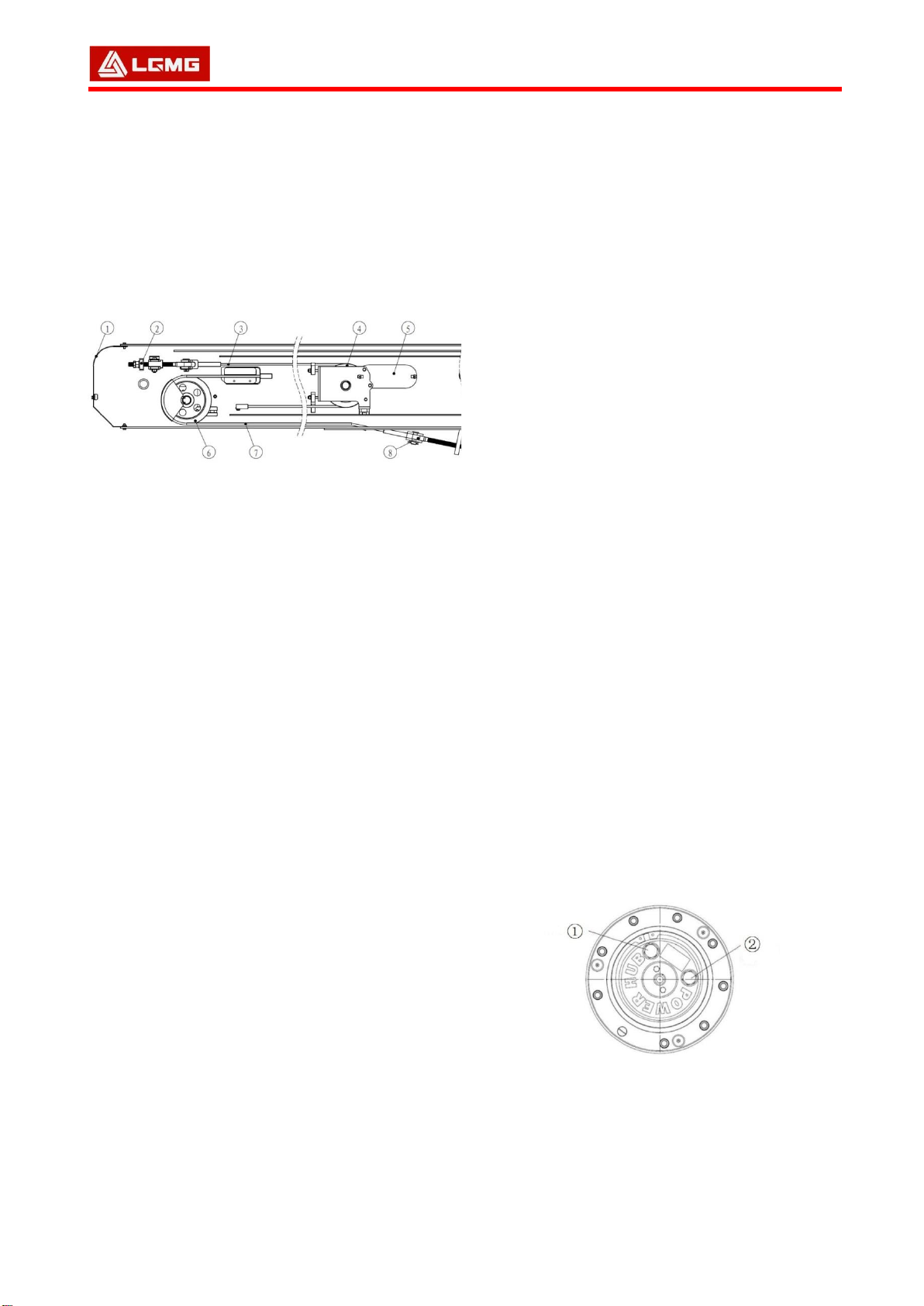
1.2 Inspecting the Pivoting
Support
1) The turntable shall rotate smoothly without
jamming, and meshing play between the
turntable bearing and the swing gearbox is
measured using a feeler gauge, which shall
be between 0.2mm and 0.3mm.
Measurement is conducted every 250 h or
quarterly.
Unscrew bolt 6 and locking nut 5
Turn adjusting bolt 4 to adjust the position
of the swing gearbox
Measure play between the turntable
bearing and the swing gearbox using a
feeler gauge
If the play ranges from 0.2mm to 0.3mm,
tighten lock nut 5 and bolt 6
Measure play between the turntable
bearing and the swing gearbox again to
verify the measurement
Tighten bolt 6, and torque to (595±5)N•m.
2) Check lubrication in the turntable bearing
and the swing gearbox at intervals of 100
hours. It is necessary for maintaining
performance and maintenance life to
lubricate the turntable bearing frequently.
Incorrect lubrication will cause damage to
components.As shown in Figure 11-1, find
the grease port 3 on the side of the bearing,
swing the turntable multiple times while
filling grease until grease overflows from
the upper and lower fixed surfaces of the
bearing. Lubricating grease must be:
Lubrication EP2 or equivalent.
3) Inspect the lubrication of the turntable
bearing and the swing gearbox, if
necessary, clean the gear surface, and
recoat with grease.
△
!Caution: In the case of an extremely dirty
working environment, increase the oil filling
frequency.
1.3 Inspecting the Boom
Wear Pad
1) Inspect the wear pad every 1,000 h or
yearly.
2) The wear pad is located on the housing
surface and inner wall of the boom to
reduce friction. It is necessary for safe
operation of the machine to maintain the
wear pad in good condition. Continuous
use of wear pads that are extremely worn
will result in damage to components and
unsafe operating conditions.
3) Extend the boom to check if the wear pad
loosens, if the wear pad loosens, torque the
securing bolt to: 28Nm. Inspect play
between the wear pad and the boom, if the
play is more than 1mm, arrange shims to