LI-COR LI-6400XT User manual

Adding Wireless Connectivity to the LI-6400XT
In Five Easy Steps
Introduction
Wireless connectivity for the LI-6400XT has been a frequently
requested option, mostly to enhance the ease of remote
control of the instrument or to provide an easier way to
download data. Although not a native feature, it is possible to
modify the LI-6400XT to either join or create a wireless
network through the addition of a modified Apple AirPort
Express™. This document will detail the steps needed to add
wireless capability to the LI-6400XT. Note that this modifica-
tion works only for XT instruments since it relies on connect-
ing the LI-6400XT via Ethernet to the AirPort Express.
Required Equipment
●Apple Airport Express Base Station (MC414LL/A)
●DC-DC adjustable step-down voltage regulator (we used
Arrela Lm2596)
●Red and black 22 AWG wiring
●Controlled DC power supply
●DC voltage meter
Required Tools
●3/4" putty knife and/or flat-head screwdriver
●3M Double-sided urethane foam tape
●Red and black 22 AWG wiring
●Torx T8 screwdriver
●Torx T5 screwdriver
●Solder and soldering iron
●Nail polish or threadlock
●Wire stripping tool
Step 1: Disassembling the Apple AirPort Express™
Base Station
First and foremost, verify that the AirPort Express works
before performing any of the subsequent steps below. Plug it
in, power it up, and make sure you can connect to it and
access the firmware using the software provided by Apple.
This assures you that if you have a defective router, it is
addressed before you (A) go through making the modifica-
tions, and (B) before you void Apple’s warranty.
The AirPort Express is not designed to be taken apart by end-
users; nevertheless, with some patience and the judicious
application of force, it is possible to open the outer case
without destroying the router. To do this, start on the side of
router that contains the small LED. Begin prying with a
flathead screwdriver or putty knife to the right of this side’s
center. When the side starts to open up, move to the next
Continued on next page
side, taking care to not pry directly on the center connector
resides. Continue prying each side, off-of-center, until the top
of the AirPort Express is off. Note that the internal corner
connectors will likely break off while removing the top cover;
this is okay as long as the internal center connectors are not
broken. Needless to say, you have voided the warranty
provided by Apple at this point.
Once the AirPort Express is open, you should see something
similar to Figure 1. The goal now is to remove the power
supply and replace it with the voltage regulator. The power
supply is under the “L” shaped metal cover that is highlighted
in Figure 1. There will be five screws that need to be removed
to get this cover off. These screws require the Torx screwdriv-
ers listed above. When the metal shield is off, continue
removing other screws holding down the circuit board; the
entire circuit board needs to be removed from the AirPort
Express case before it is possible to take out the power supply.
The removed assembly should appear as in Figure 2.
Figure 1. AirPort Express with top cover removed. The AC to
DC converter is located under the L-shaped metal cover.
Ground and +3.3V terminal connections also shown.
Figure 2. AirPort Express with internal components removed
from the plastic housing. The power supply can be removed
from the other components at this time (highlighted above).

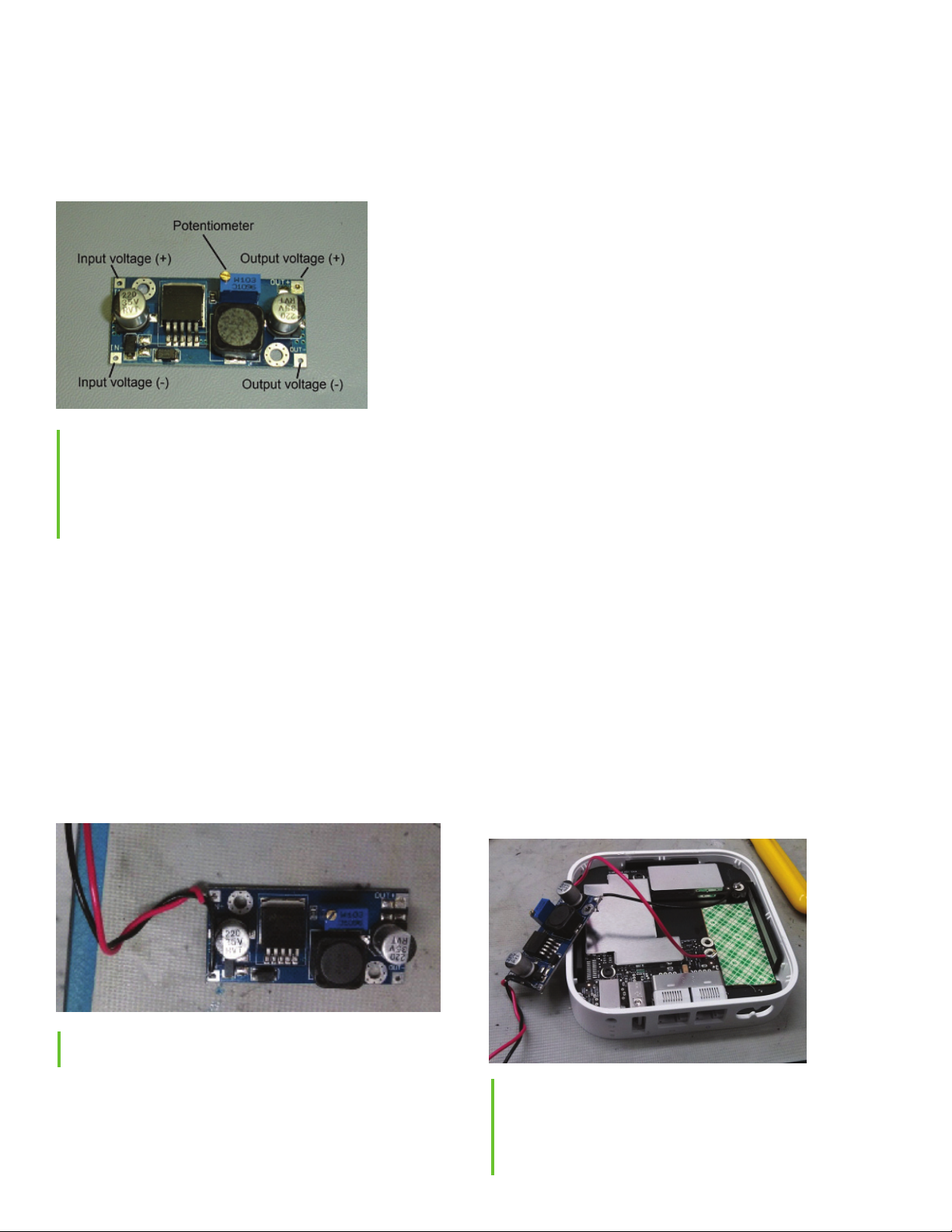
Step 2: Wiring voltage regulator terminals
The voltage regulator is the component that makes is possible
to run the AirPort Express off of a DC power source. The key
components of the voltage regulator are shown in Figure 3.
The key steps are (1) solder wires to the input and output
sides of this regulator and then (2) adjusting the output of the
regulator to 3.3 V.
Figure 3. Voltage regulator. To properly adjust the voltage
regulator (detailed in Step 3), apply a DC voltage source
between 4.3-30V on the input voltage side and then monitor the
output voltage on the opposite side using a voltage meter.
Turn the screw on the potentiometer until the output voltage
reads 3.3V.
Cut approximately a 16-inch length of both the red and black
wiring. These wires will be soldered to the “in” side of the
voltage regulator. Strip approximately 1/4 inch of insulation
off of each end. Using the soldering iron, put a small amount
of solder on the ends of each wire. Then, form one end of
each wire into a hook and hook these ends into the appropri-
ate terminals in the voltage regulator (red wire to the positive
terminal and black wire to the negative terminal; if using
alternative colors, just keep your color convention consistent
throughout). Solder the wires to the terminal by placing a
small amount of solder on both the terminal and wire. To add
some strain relief, you can twist the wires together a couple
times as shown in Figure 4.
Figure 4. Voltage regulator with wiring soldered to the ‘in’ side
of the device.
The next step is to solder wires to the “out” side of the voltage
regulator. Cut a 4-inch length of black and red wiring, again
stripping 1/4 inch of insulation off of each of the four ends,
soldering these ends, and then forming the ends into hooks.
Solder one end of each wire to the appropriate terminal on the
voltage regulator’s “out” side.
Step 3: Set voltage regulator
Setting the voltage regulator is the next step. However, a
voltage of some kind needs to be applied to the incoming
terminals. Then you can measure and adjust the voltage on
the “out” side using a voltmeter. The supply voltage can be
anywhere between about 4.3 - 30VDC. After a voltage is
applied to the “in” side, monitor the voltage on the “out” side
using a voltage meter and turn the potentiometer dial so that
the “out” side voltage reads 3.3 V. See Figure 3 to better
understand the voltage regulator and how to adjust it. Then,
apply some nail polish or threadlock to the potentiometer dial
to prevent inadvertently moving the dial later on. Then,
check the voltage on the “out” side one more time. If the
voltage on the “out” side isn’t adjusted to 3.3 V, the AirPort
Express may not work correctly or could be damaged, thus
releasing the device’s magic smoke.
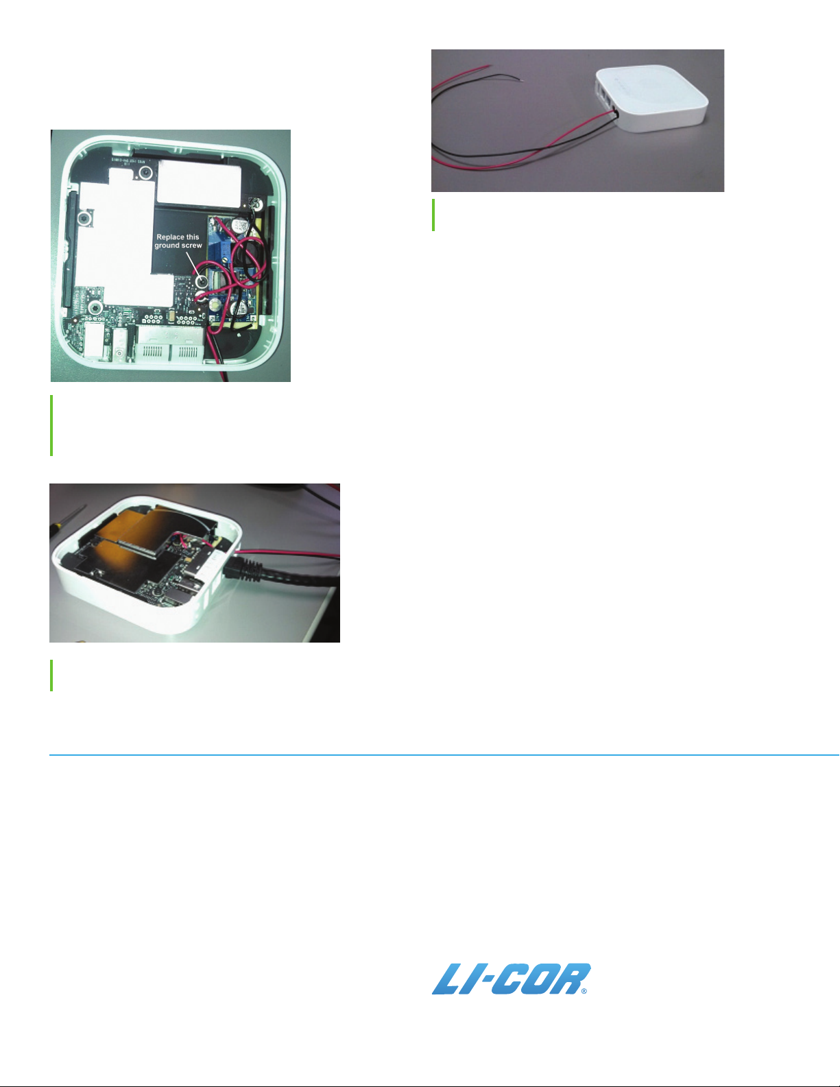
Step 4: Connecting voltage regulator to the AirPort
Express
Connecting the voltage regulator to the AirPort Express
simply involves soldering the two wires on the “out” side to
the ground and +3.3 V terminals in the router. Solder the
negative wire to the router’s ground terminal and solder the
positive wire to the +3.3 V terminal (see Figure 5). You can
now tear off the remaining side of the double-sided sticky tape
and place the voltage regulator into the AirPort Express on
top of the sticky tape. Now, replace the ground screw as
indicated in Figure 6 using the appropriate Torx screwdriver.
This will serve as a post for strain relief. The wires that are
connected to the voltage regulator’s “in” side can be wound
around this post before routing them through the AC cord
connection hole in the AirPort Express case.
Figure 5. Photo showing the wiring connections of the ‘out’
side of the voltage regulator to the appropriate terminals of the
AirPort Express. The negative lead from the voltage regulator
should be soldered to the ground terminal and the positive lead
should be soldered to the +3.3V terminal.

© 2015, LI-COR, Inc. LI-COR is a registered trademark of LI-COR, Inc. AirPort Express is a
registered trademark of Apple, Inc.
LI-COR Distributor Network: www.licor.com/env/distributors
LI-COR Biosciences - Global Headquarters
4647 Superior Street
Lincoln, Nebraska 68504
Phone: +1-402-467-3576
Toll free: 800-447-3576
Fax: +1-402-467-2819
envsales@licor.com • envsupport@licor.com • www.licor.com/env
Regional Offices
LI-COR GmbH, Germany
Serving Andorra, Albania, Cyprus, Estonia, Germany, Iceland, Latvia,
Lithuania, Liechtenstein, Malta, Moldova, Monaco, San Marino, Ukraine,
and Vatican City.
LI-COR Biosciences GmbH
Siemensstraße 25A
61352 Bad Homburg, Germany
Phone: +49 (0) 6172 17 17 771 • Fax: +49 (0) 6172 17 17 799
envsales-gmbh@licor.com • envsupport-gmbh@licor.com
LI-COR Ltd., United Kingdom
Serving Denmark, Finland, Ireland, Norway, Sweden, and UK.
LI-COR Biosciences UK Ltd.
St. John’s Innovation Centre
Cowley Road
Cambridge
CB4 0WS
United Kingdom
Phone: +44 (0) 1223 422102 • Fax: +44 (0) 1223 422105
envsales-UK@licor.com • envsupport-UK@licor.com
TTP-7, 10/15
To test the new setup, apply DC power (4.3 - 30V) to the wires
that lead out of the router. The router should appear as if it is
booting up normally. If the router’s LED does not light up, or
if you see sparks and smoke, something has gone awry.
Figure 6. Photo showing installation of voltage regulator into
AirPort Express. Note that the wiring from ‘in’ side of voltage
regulator is looped around the ground screw post before
exiting the side of the router housing.
Step 5: Connecting the AirPort Express to the
LI-6400XT
There are a few options for powering the DC-powered
AirPort Express. One option involves wiring to the internal
LI-6400XT power supply. This is accomplished by soldering
two wires to the LI-6400XT. In this case, the wires should be
soldered to the switched +12V line and ground. Alternatively,
one could design a ‘Y’ cable that plugs into an LI-6400 battery
on one end, and then the other two ends would connect to the
router and LI-6400 console. Finally, there’s always the option
of just powering it using a separate battery.
Figure 7. Photo showing reinstallation of metal cover over
voltage regulator.
Figure 8. Router appearance after completion of all internal
modifications.
Other LI-COR Laboratory Equipment manuals

LI-COR
LI-COR LI-6400 User manual

LI-COR
LI-COR LI-8100 User manual

LI-COR
LI-COR Odyssey User manual

LI-COR
LI-COR LI-6800 User manual

LI-COR
LI-COR 6400-09 User manual

LI-COR
LI-COR Odyssey M 3340 User manual

LI-COR
LI-COR Odyssey CLx User manual

LI-COR
LI-COR Odyssey CLx User manual

LI-COR
LI-COR LI-6800 User manual

LI-COR
LI-COR Odyssey XF User manual