IMPORTANT!
DO NOT DISCARD THE SHIP KIT LOCATED ON TOP OF THE DECK AND BELT. ALL NECESSARY COMPONENTS
NEEDED TO COMPLETE THE INSTALLATION ARE LOCATED IN THE SHIP KIT.
IMPORTANT!
NE JETEZ PAS LE KIT D’EXPÉDITION PLACÉ SUR LE DESSUS DU PLATEAU ET SUR LE TAPIS. IL CONTIENT TOUS LES
ÉLÉMENTS NÉCESSAIRES POUR L’INSTALLATION.
Step 1
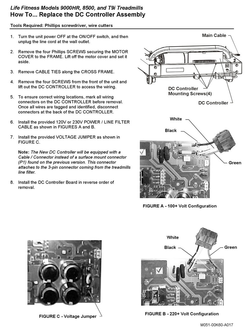
Remove the four SCREWS securing the MOTOR COVER to the FRAME (C).
Remove the MOTOR COVER.
Step 2
Remove the USER LEFT HANDRAIL (#1)(with wire harness) from the ship kit
and lay it on the deck with the rectangular tube end facing the motor
compartment and behind the USER LEFT HANDRAIL MOUNTING BRACKET (D).
Step 3
(Models 9100 & 9500HR Only)
Carefully route the 10-PIN CONNECTOR (10-P) leading from the rectangular
tube end of the USER LEFT HANDRAIL (#1) through the opening at the USER
LEFT HANDRAIL MOUNTING BRACKET (D) and through the access hole
located at the inside FRAME (C) wall.
NOTE: BE CAREFUL NOT TO DAMAGE THE WIRE HARNESS WHEN
ROUTING IT THROUGH THE FRAME MEMBERS.
BE REMARQUE : VEILLEZ À NE PAS ENDOMMAGER LE FAISCEAU
LORS DE SON PASSAGE PAR LES ÉLÉMENTS DU CADRE.
(Model 9700HR Only)
Connect the 10-PIN CONNECTOR (10-P) leading from the rectangular tube end
of the USER LEFT HANDRAIL (#1) to the 10-PIN CONNECTOR (10-P) leading
from the USER LEFT HANDRAIL MOUNTING BRACKET (D).
Step 4
Raise the USER LEFT HANDRAIL (#1) off the deck and slide the rectangular tube end over the USER
LEFT HANDRAIL MOUNTING BRACKET (D) until it rests on the FRAME (C).
CAUTION: BE CAREFUL NOT TO PINCH THE WIRE HARNESS.
MISE EN GARDE : VEILLEZ À NE PAS PINCER LE FAISCEAU.
Step 5
Install one HANDRAIL MOUNTING BOLT (#2) with one FLAT WASHER (#16) in the mounting hole located
on the top narrow surface of the USER LEFT HANDRAIL (#1). Tighten the bolt until snug. Install two
HANDRAIL MOUNTING BOLTS (#2) and FLAT WASHERS (#16) into the remaining two mounting holes
located on the inside surface of the USER LEFT HANDRAIL (#1). Leave these two bolts loose at this
time.
Step 6
Connect the 10-PIN CONNECTOR (E) to the 10-PIN JACK (F) located on the CONTROL BOARD (G).
Step 7
Locate the USER RIGHT HANDRAIL (#3) and slide the rectangular tube end over the USER RIGHT
HANDRAIL MOUNTING BRACKET until it rests on the FRAME (C).
Step 8
Install one HANDRAIL MOUNTING BOLT (#2) with one FLAT WASHER (#16) in the mounting hole located
on the top narrow surface of the USER RIGHT HANDRAIL (#3). Tighten the bolt until snug. Install two
HANDRAIL MOUNTING BOLTS (#2 & #4) and FLAT WASHERS (#16) into the remaining two mounting
holes located on the inside surface of the USER RIGHT HANDRAIL (#3). Leave these two bolts loose at
this time.
NOTE: HANDRAIL MOUNTING BOLT #4 SHOULD BE LOCATED IN THE LOWER INSIDE
MOUNTING HOLE OF THE USER RIGHT HANDRAIL
REMARQUE : LE BOULON DE FIXATION DE BARRE
LATÉRALE Nº 4 DOIT SE TROUVER DANS L’ORIFICE
INTERNE INFÉRIEUR DE LA BARRE LATÉRALE
DROITE.
Step 9
Locate the FRONT HANDLEBAR ASSEMBLY (#14). With the bend facing upward and toward
the front of the unit, align the FRONT HANDLEBAR ASSEMBLY with the access hole located on
the inside of the USER LEFT HANDRAIL (#1).
(Models 9500HR & 9700HR) Feed the HEART RATE ELECTRODE CABLE (K) and the SMART
STOPSYSTEM CABLE (L) through the access hole and up through the top of the USER LEFT
1
KL
1
3
C
D
Models 9700HR
1
16
3
D
C
C
2
4
