Page 2 of 6
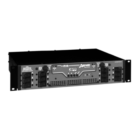
RE82 RACK MOUNT DIMMER
Revision 2.5 OWNER’S MANUAL 02/17/2022
www.lightronics.com
Lightronics Inc 509 Central Drive, Virginia Beach, VA 23454 TEL 757 486 3588
DESCRIPTION
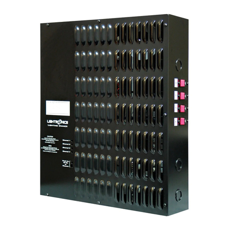
The RE82 is an 8 channel dimmer with a maximum
capacity of 2,400 watts per channel giving a total of
19,200 watts. The RE82 is controlled by a lighting
console. The unit can be supplied to use either the
DMX-512 control protocol or the LMX-128 control
protocol. Channels A - D and/or channels E - H may
be switched to operate in "relay" mode. In relay
mode, channels are either full on or full off (non-dim)
depending on console fader position. The unit is
overcurrent and overtemperature protected. A fan is
used to ensure proper cooling. The dimming channel
starting address may be reassigned in multiples of 4
channels via switches in the front panel.
POWER REQUIREMENTS
Each RE82 requires BOTH PHASES of a SINGLE
PHASE 50/60 Hz, 120/240 VOLT AC service or
TWO PHASES of a THREE PHASE 50/60 Hz,
120/208 VOLT AC service. The neutral conductor is
shared by two hots, so it is important the two hots
used are of different phases. EACH PHASE must be
capable of providing 80 AMPS. One or more RE82
dimmers are to be installed into a standard 19"
equipment rack with provisions for connection to an
appropriate electrical service in accordance with the
National Electrical Code.
LIGHTING LOAD CAPACITY
Each RE82 channel has a 2400 Watt MAXIMUM
rating and is protected by a fast acting 20 Amp
circuit breaker. 20 Amps equates to 2400 Watts at
120VAC. If you operate a channel at 2400 watts
then you are very close to tripping the breaker. This
will occur if AC line voltages are high or you have
power surges. Other conditions which may cause
the breaker to trip include turning on a cold lamp, or
raising the fader quickly to full intensity. A maximum
practical load of 2000 Watts per channel will allow
for some overhead and help prevent breaker
tripping.
INSTALLATION
PLACEMENT
The RE82 is designed to be mounted in a standard
19" equipment rack using four mounting holes in the
face plate. If the dimming system will be used for
touring shows, it is recommended you provide
additional support for the rear of the unit. The
dimmer is fan cooled and requires no space
between units when multiple dimmers are used
together in a rack. Air enters the dimmer through
slots on the side and exits through holes in the
bottom of the face plate. Make certain these
ventilation holes are not obstructed. Do not place the
RE82 where it will be exposed to moisture or
excessive heat.
POWER CONNECTIONS
Power enters the RE82 through the rear of the unit
via a knockout sized for 1" conduit. Inside the RE82
is a terminal block with three lugs. The "H1" and
"H2" terminals are the line connections or "hots".
The center connection labeled "N" is the neutral.
There is an additional ground lug labeled "G" located
near the terminal block. This lug is for connecting
the chassis to earth ground.
Consult your local electrical codes to determine the
proper wire type and wiring methods for your
installation. Connect a ground wire to the ground lug
"G" first. Next connect the neutral to the center lug
"N" on the terminal block, then connect one hot to
the lug of the terminal block marked "H1" and the
other hot to the "H2" lug of the terminal block .
CONTROL SIGNALS
The RE82 is supplied to use one of two types of
control signal. Either DMX-512 control or LMX-128
control is supplied when ordered. The front panel is
marked to show which protocol can be used.
DMX CONTROL
The DMX-512 control signal enters the RE82
through a 5 pin male XLR connector on the rear of
the unit. The 5 pin female XLR connector is used to
continue DMX out to other equipment in the system.
Normally the male connector is used for the DMX
input and the female connector is used as a DMX
output. These connectors are wired in parallel so
either connector may be used as input or output.
The table below shows the control signal connector
pin assignments.
WARNING
MAKE CERTAIN POWER IS
REMOVED FROM THE FEED
CIRCUITS BEFORE YOU BEGIN
INSTALLATION.
