Lippert Tri-Fold Sofa Operating instructions

Rev: 05.22.23 Tri-Fold Sofa Troubleshooting and Service Manual_v2
Tri-Fold Sofa
Troubleshooting and
Service Manual

Rev: 05.22.23 Page 2 CCD-0001740
TABLE OF CONTENTS
Introduction 3
Additional Information Sources 3
Safety 3
Operation Instructions 4
Preparation 5
Resources Required 5
Back Cushion Replacement Instructions 5
Full Cushion Assembly 5
Cushion Foam 5
Cushion Cover 5
Stationary Back Replacement Instructions 6
Full Stationary Back Assembly 6
Stationary Back Interior Foam 6
Stationary Back Interior Frame 6
Stationary Back Cover 6
Couch Seat Replacement Instructions 7
Couch Seat Assembly 7
Couch Seat Interior Foam 7
Couch Seat Interior Frame 8
Couch Seat Cover 8
Couch Seat Legs 8
Middle Seat Replacement Instructions 8
Middle Seat Assembly 8
Middle Seat Interior Foam 9
Middle Seat Interior Frame 9
Middle Seat Cover 9
V2 Frame Replacement Instructions 9
Rear Kick Rail Replacement Instructions 10
Arm Insert Replacement Instructions 11
Foot Assembly Replacement Instructions 11
Care and Cleaning 11
Maintenance 11
Knock Down Sofa Preparation 12
Resources Required 12
Assembly Instructions 13

Rev: 05.22.23 Page 3 CCD-0001740
Introduction
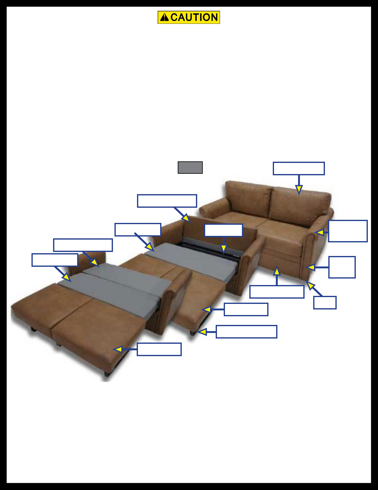
Our one-piece, steel frame Tri-Fold Sofa requires no spare mattress to store. In just four simple steps, it transforms
into a comfortable bed. Traditional hide-a-beds have uncomfortable mattresses with support bars that can make
sleeping uncomfortable. Air mattress hide-a-beds eliminate the support bar issue, but can be damaged more easily
and become unusable. The Tri-Fold Sofa converts from sofa to a very supportive, high-density foam sleep surface in
four simple steps. Now campers can actually look forward to sleeping on the couch!
Additional Information Sources
For more resources about interior furniture products , more detailed installation processes and operating
procedures, and/or for information on the assembly or individual components of these products,
please visit: https://support.lci1.com/furniture/.
Additional information can also be obtained from lci1.com/support or by downloading the free LippertNOW
app. The app is available on Apple App Store® for iPhone® and iPad® and also on Google Play™ for
Android™ users.
Apple App Store®, iPhone®, and iPad® are registered trademarks of Apple Inc.
Google Play™ and Android™ are trademarks of Google Inc.
The "WARNING" symbol above is a sign that a procedure has a safety risk involved and may cause
death or serious personal injury if not performed safely and within the parameters set forth in this
manual. Failure to follow instructions provided in this manual may result in death, serious personal
injury and/or severe product and property damage, including voiding of the component warranty.
The “CAUTION” symbol above is a sign that a safety risk is involved and may cause personal injury
and/or product or property damage if not safely adhered to and within the parameters set forth
in this manual. Always wear eye protection when performing installation procedures. Other
safety equipment to consider would be hearing protection, gloves and possibly a full face shield,
depending on the nature of the task.
Safety
Read and understand all instructions before installing or operating this product. Adhere to all safety labels.
This manual provides general instructions. Many variables can change the circumstances of the instructions,
i.e., the degree of difficulty, operation and ability of the individual performing the instructions. This
manual cannot begin to plot out instructions for every possibility, but provides the general instructions,
as necessary, for effectively interfacing with the device, product or system. Failure to correctly follow the
provided instructions may result in death, serious personal injury, severe product and/or property damage,
including voiding of the Lippert limited warranty.

Rev: 05.22.23 Page 4 CCD-0001740
Fig. 1
Operation Instructions
NOTE: Refer to (Fig. 1) for steps 1-5.
1. Remove back cushions from the hook and loop fabric strips and set aside.
2. Fold out the couch seat to expose the middle seat.
3. Fold out the couch seat legs and set upright.
4. Fold down the stationary back.
5. Use back cushions as headrest or pillows.
Back Cushion
Couch Seat
Couch Seat Legs
Couch Seat
Front Kick Rail
Foot
Arm
Insert
Arm
Assembly
Stationary Back
Middle Seat V2 Frame
Middle Seat
Stationary Back
Moving parts can pinch, crush or cut. Keep clear and use caution during assembly.
NOTE: Recently added Knock Down Sofa is limited to fasteners and brackets and is assembled with limited
tools. See assembly instructions see page 12.

Rev: 05.22.23 Page 5 CCD-0001740
Fig. 2
Preparation
Resources Required
NOTE: Resources required may vary due to actual operation performed. Listed below is what may be
required.
Hook and Loop
Fabric Strips
• Cordless or electric screw gun or drill
• ½" Socket (Import tri-fold sofas may use a
8mm socket)
• Appropriate screw drivers
• Appropriate drive bits
Back Cushion Replacement Instructions
Full Cushion Assembly
1. Remove cushion from sofa. The cushions are held in place by hook and loop fabric strips (Fig. 2).
2. Place new cushion back on sofa.
Cushion Foam
1. Remove back cushion from the sofa. The cushions are attached by hook and loop fabric strips (Fig. 2).
2. Unzip and remove cover from foam.
3. Discard the foam.
4. Insert new foam into cover.
5. Zip cover completely around new foam.
6. Place cushion back on sofa.
Cushion Cover
1. Remove the cushion from the sofa. The cushions are attached by hook and loop fabric strips (Fig. 2).
2. Unzip and remove the cover from foam.
3. Discard the cover.
4. Insert new cover around foam cushion.
5. Zip new cover completely around foam.
6. Place cushion back on sofa.

Rev: 05.22.23 Page 6 CCD-0001740
Stationary Back Replacement Instructions
Full Stationary Back Assembly
1. Remove back cushions from sofa and set aside.
2. Unfold front seat and middle seat to expose mounting bolts and nuts (Fig. 3).
3. Remove the two nuts and two bolts from each mounting bracket and set aside (Fig. 4). Discard back
assembly.
Fig. 4
Fig. 3 Stationary Back
V2 Frame Mounting Bracket
4. Set new back assembly in place with holes in mounting brackets aligned with holes in V2 frame.
5. Insert bolts through mounting bracket and V2 frame.
6. Secure bolts with nuts.
7. Fold front seat and middle into stored position.
8. Reattach back cushions.
NOTE: To replace the stationary back interior foam, stationary back interior frame or stationary back cover,
the stationary back assembly needs to be removed first for easier access.
Stationary Back Interior Foam
1. Unzip cover from the stationary back.
2. Remove and discard foam.
3. Place new foam on the interior frame.
4. Slip cover over the interior frame and foam.
5. Zip cover completely.
Stationary Back Interior Frame
1. Unzip cover from the stationary back.
2. Remove and discard the old interior frame.
3. Place foam on the new interior frame.
4. Slip cover over the interior frame and foam.
5. Zip cover completely.
Stationary Back Cover
1. Unzip cover from the stationary back.
2. Remove and discard the old cover.
3. Slip new cover over the interior frame and foam.
4. Zip cover completely.

Rev: 05.22.23 Page 7 CCD-0001740
Fig. 5 Fig. 6
Cotter Pin Clevis Pin
Steel Tab
Couch Seat Replacement Instructions
Couch Seat Assembly
1. Remove cotter pins from the end of the clevis pins (Fig. 5).
NOTE: There is one clevis pin on each side of the Tri-fold sofa at the bottom of the seat. The clevis pins are
attached to the steel tab connected to the middle seat.
2. Push clevis pin through hole (Fig. 6) of the steel tab with a screw driver.
3. Repeat on the other side. The couch seat will detach from the middle seat.
NOTE: The steel tab (Fig. 6) connects the couch seat to the middle seat. The shorter end of the steel tab
goes to the V2 frame. The longer end of the steel tab goes to the seat.
NOTE: To replace the couch seat interior foam, couch seat interior frame or couch seat cover, the couch
seat assembly needs to be removed first for easier access.
Couch Seat Interior Foam
1. Unzip cover from the couch seat (Fig. 7).
2. Remove and discard foam.
3. Place new foam on the interior frame.
4. Slip cover over the interior frame and foam.
5. Zip cover completely.
Fig. 7

Rev: 05.22.23 Page 8 CCD-0001740
Fig. 8
Bolt
Nut
Fig. 9 Fig. 10 Fig. 11
Clevis Pin
V2 Frame
Cotter Pin
Couch Seat Interior Frame
1. Unzip cover from the couch seat.
2. Remove and discard the old interior frame.
3. Place foam on the new interior frame.
4. Slip cover over the interior frame and foam.
5. Zip cover completely.
Couch Seat Cover
1. Unzip cover from the couch seat.
2. Remove and discard the old cover.
3. Slip new cover over the interior frame and foam.
4. Zip cover completely.
Couch Seat Legs
1. Remove the legs by removing the (4) bolts and nuts (Fig. 8) on either side.
2. Place new legs in the same position the old legs were removed from and add bolts and nuts.
Middle Seat Replacement Instructions
Middle Seat Assembly
1. Remove one side of V2 Frame first. Start by removing three screws using a combo head square drive (Fig. 9).
2. Remove cotter pin (Fig. 10).
3. Lift up, push clevis pin out from the steel tab using a screw driver (Fig. 11).
4. Repeat 2-3 for the other side of the seat.
NOTE: During replacement, make sure the pillow side of the middle seat is up.
NOTE: To replace the middle seat interior foam, middle seat interior frame or middle seat cover the middle
seat assembly needs to be removed first for easier access.

Rev: 05.22.23 Page 9 CCD-0001740
Middle Seat Interior Foam
1. Unzip cover from the middle seat.
2. Remove and discard foam.
3. Place new foam on the interior frame.
4. Slip cover over the interior frame and foam.
5. Zip cover completely.
Middle Seat Interior Frame
1. Unzip cover from the middle seat.
2. Remove and discard the old interior frame.
3. Place foam on the new interior frame.
4. Slip cover over the interior frame and foam.
5. Zip cover completely.
Middle Seat Cover
1. Unzip cover from the middle seat.
2. Remove and discard the old cover.
3. Slip new cover over the interior frame and foam.
4. Zip cover completely.
V2 Frame Replacement Instructions
NOTE: To replace the V2 frame the middle seat, couch seat and stationary back assembly needs to be
removed first for easier access.
1. Remove the V2 frame by removing the three screws on each side.
2. Install the V2 frame by making sure the U shape faces the back (Fig. 12).
3. Install the three screws on each side (Fig. 13).
Fig. 12 Fig. 13

Rev: 05.22.23 Page 10 CCD-0001740
Fig. 14
Screws
Fig. 15
Front Kick Rail Replacement Instructions
NOTE: To replace the front kick rail, the V2 frame, middle seat, couch seat and stationary back assembly
need to be removed first for easier access.
1. Remove the old front kick rail by removing the three screws on each side (Fig. 14).
2. Install the new front kick rail by making sure rails are flush with bottom of kick board. Insert the three
screws on each side.
Rear Kick Rail Replacement Instructions
NOTE: To replace the rear kick rail, the V2 frame, middle seat, couch seat and stationary back assembly
needs to be removed first for easier access.
1. Remove the old kick rail by cutting a small slit in the Typar® material to show the two screws on each
side. Remove the two screws on each side (Fig. 15) of the couch.
2. Install the new rear kick rail by inserting the two screws on each side.

Rev: 05.22.23 Page 11 CCD-0001740
Arm Insert Replacement Instructions
1. The arm insert has a tack strip on the back. Remove the old arm insert by prying the insert off the arm.
2. Install the new arm insert by tapping on the front with a mallet (Fig. 16).
Fig. 16
Fig. 17
Care and Cleaning
Use warm water only to clean material. Lippert does not suggest any chemicals of any sort.
Maintenance
It is recommended that the bolts and nuts of the legs of the fold out portion of the Tri-Fold Sofa be tightened on a
monthly basis. Over time the bolts and nuts can loosen, which could cause damage to the middle cushion cover.
Arm Insert
Foot Assembly Replacement Instructions
1. Remove the old foot assembly by removing the two screws at the bottom of the foot assembly (Fig. 17).
2. Install the new foot assembly by inserting the two screws into the bottom of the new foot assembly
(Fig. 17).

Rev: 05.22.23 Page 12 CCD-0001740
Knock Down Sofa Preparation
Resources Required
NOTE: Resources required may vary due to actual operation performed. Listed below is what may be
required.
• Cordless or electric screw gun or drill
• Appropriate screw drivers
• Appropriate drive bits
NOTE: Knock Down sofa comes in two boxes. Need spacious place to lay items out flat.
1. Remove the Knock Down sofa pieces from the packaging.
2. Place the arm rest pieces, front kick rail, and rear kick rail flat on the floor (Fig. 18).
3. Set the seating cushion, u-bar (comes assembled) and the back of the sofa aside.
NOTE: The hardware is two different colors making assembly quick and easy. The rear kick rail hardware
will match up with the attached hardware on the arm rest and the front kick rail will match up with
the front arm rest.
Fig. 18
Front Kick Rail
Arm Rest
Arm Rest
Rear Kick Rail
Brackets
Brackets

Rev: 05.22.23 Page 13 CCD-0001740
Assembly Instructions
NOTE: Be sure that the front kick rail is correctly oriented with the lettering facing the front (Fig. 19).
1. Lift the arm rests to an upright position and lift the rear kick rail end and slide bracket into the rear slot
bracket attached to the arm rest. (Fig. 20). Repeat the process on the opposite side.
2. Lift the front kick rail and align the slide bracket with the slot bracket on the front arm rest (Fig. 21).
Repeat the process on the opposite side.
Fig. 19
Fig. 20
NOTE: It is necessary to remove all screws that are assembled with the U-bar and seat cushion assembly.
There is six screws total, four in the back u-bar and two on each side (Fig. 22).
Fig. 21
Side screw
Back screws
Fig. 22

Rev: 05.22.23 Page 14 CCD-0001740
3. Unfold the u-bar down adjacent to the back rear kick rail (Fig. 23). Insert the black tabs on the u-bar
into the L-brackets on the arm rest sides and push down and to the side to lock it in place. (Fig. 24)
Repeat process on opposite side.
U-bar
Fig. 23 Fig. 24
4. Secure arm rest and u-bar with the two side screws that were previously removed (Fig. 25).
5. Align the back sofa brackets with the holes on the back u-bar (Fig. 26) and secure with the remaining
screws.
Fig. 25 Fig. 26
Black tabs

Rev: 05.22.23 Page 15 CCD-0001740
6. Once the U-bar and back of the sofa are secure fold the seat onto the sofa (Fig. 27).
Fig. 27
7. Pull the strips off (Fig. 28) exposing the Velcro on the back of the sofa.
8. Attach the back cushions to the sofa back.
Fig. 28
Seating cushions
Complete seating area
Velcro strips
Complete sofa assembly
NOTE: All components for the Knock Down sofa are available for replacement.

The contents of this manual are proprietary and copyright protected by Lippert.
Lippert prohibits the copying or dissemination of portions of this manual unless prior written consent from an
authorized Lippert representative has been provided. Any unauthorized use shall void any applicable warranty.
The information contained in this manual is subject to change without notice and at the sole discretion of
Lippert. Revised editions are available for free download from lippert.com.
Please recycle all obsolete materials.
For all concerns or questions, please contact Lippert
Table of contents
Other Lippert Indoor Furnishing manuals

Lippert
Lippert Cosmo 2 Euro User manual

Lippert
Lippert Moon User manual

Lippert
Lippert Bed/Table Pedestal V2 User manual

Lippert
Lippert Thomas Payne Tri-Fold Sofa Installation instructions

Lippert
Lippert Tokyo Bed User manual

Lippert
Lippert Bed/Table Pedestal V2 User manual

Lippert
Lippert Thomas Payne Seismic Theater Seating Installation instructions

Lippert
Lippert Schwintek User manual

Lippert
Lippert Compact Flyscreen User manual

Lippert
Lippert Thomas Payne series User manual