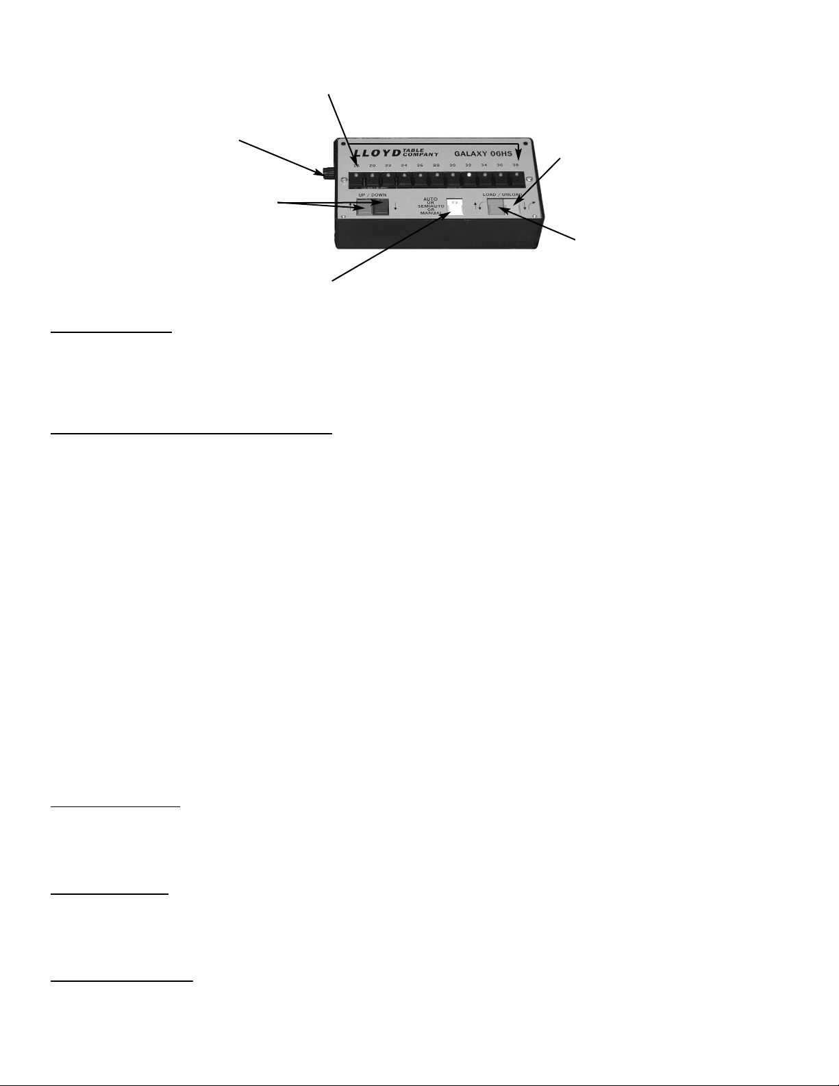
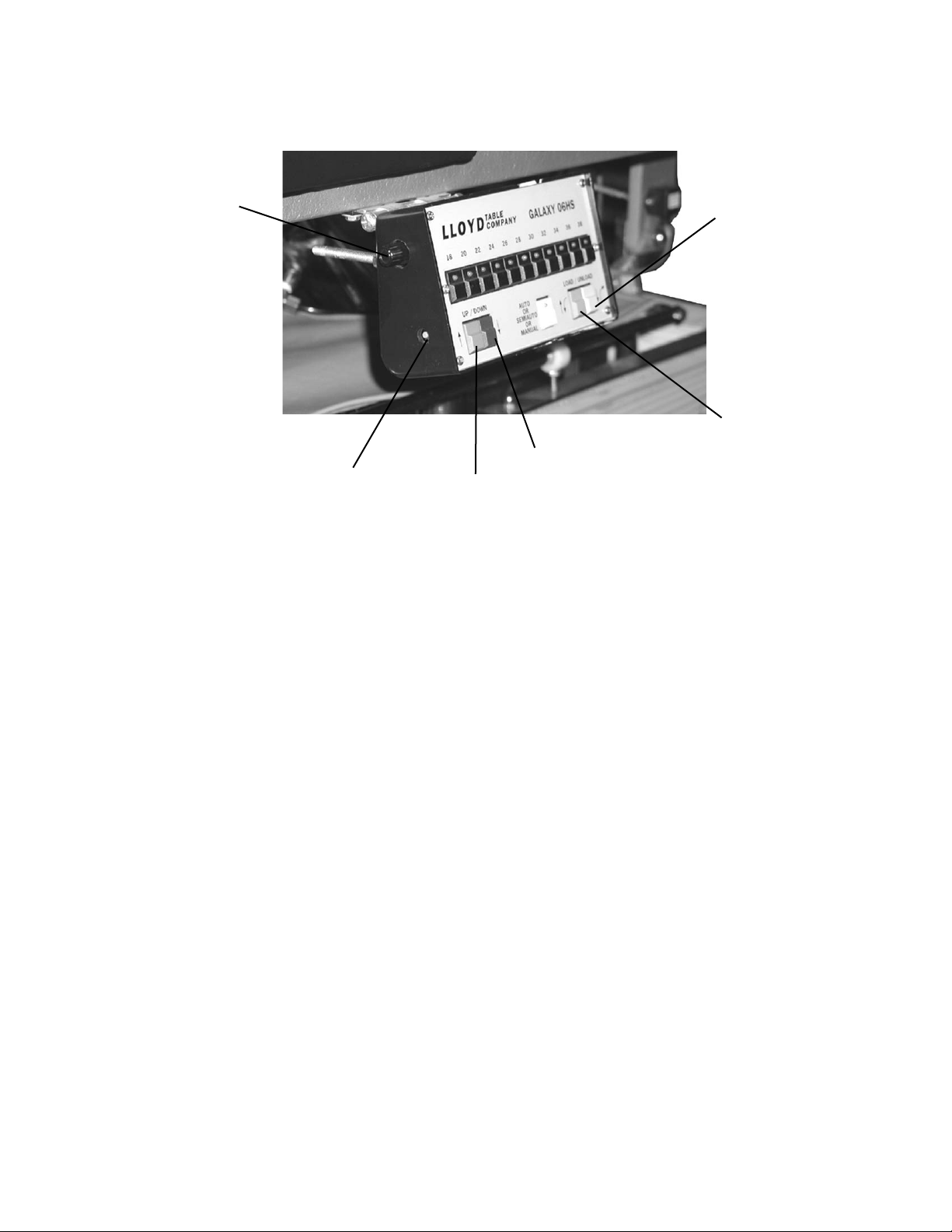
Lloyd ACTIVATOR 906HS User manual


CONTENTS
OPERATIONS PAGE
Safety and Maintenance............................................................... 1 - 2
Ankle Rest...................................................................................... 3
Master Power Switch ................................................................... 3
Tilt Safe Guard / Foot Pedal Control .......................................... 4
Height Select Panel...................................................................... 5-7
Error Code Tables ....................................................................... 19-21
PARTS / ASSEMBLY PAGE
Tilt Frame......................................................................................... 9
Base Frame...................................................................................... 10
Adjustable Ankle Cushion................................................................ 11
Foot Stand ......................................................................................... 12
Cover / Bellows................................................................................. 13
Hydraulics.................................................................................... 14
Electrical...................................................................................... 15-16
Drop T-Plevic................................................................................. 17-18
Table Serial Number
DATE 8-08

WELCOME!!
Lloyd Table Company, a proud supporter of today’s chiropractors, has established the finest line of chiropractic tables in the world.
Table products unique in versatility and function, designed to meet your needs.
Concerned for a safe working and treatment environment, Lloyd Table Company asks that you follow the safety tips below.
*Be aware of Caution and Warning labels posted throughout the table before operating any functions.
*Everyone operating the table needs to read the manual and familiarize themselves with all its functions before
operating the table with patient on it.
*A patient should never be unattended, when lying on the table.
NEVER LEAVE A PATIENT ON THE TABLE UNATTENDED!
*The patient should be positioned at or near the center of the table with arms on the armrest cushions.
*There should be no more than one operator at the controls.
*Check the tension on all drops before adjusting the patient. (See Page 7)
SAFETY
Page 1

MAINTENANCE
The following steps should be performed on a regular basis to maintain your Lloyd table in a smooth operating condition and to
assure its long life and top quality appearance.
*An initial inspection and periodic future inspections should be made to insure that nuts and bolts have not loosened
in shipping or during daily operations.
*Your Lloyd table should be lubricated every six months. Parts to be lubricated are all
pivot points, and metal to metal sliding mechanisms.
(DO NOT LUBRICATE FRICTION LOCKS)
*The cushions should be cleaned daily with a mild soap & warm water solution to
remove body oils. Rinsed & dried
*Chrome parts should be cleaned on a weekly basis for appearance.
*The hydraulic fluid recommended for the pump, is a lubriplate HO1 hydraulic oil, and should be checked
on a yearly basis.
*Perform periodic inspections for oil leaks or drips.
Page 2

Ankle Rest
Ankle Rest Adjustment
Vertical Ankle Rest
To Raise the Ankle Rest
1. Simply lift on the sides of the Ankle Rest Cushion.
2. Once the desired height is obtained the cushion will automatically lock into position when
released.
To Lower the Ankle Rest
1. From the back end of the table, support the center of the Ankle Rest Cushion with the right hand.
2. With left hand, slide the Lock Lever (No. 1) towards the left side to release lock.
3. Lower the cushion to desired height, and release the Vertical Lock Lever to lock into place.
# 1 Lock Lever
Master Power Switch
Master Power Switch
Fuse Holder
The Master Power Switch is located on the front left side of the base frame. The switch is operated by pushing on the left
or right side, marked with a zero or dash.
A. ON is indicated with a dash (-) B. OFF is indicated with a Zero (0)
WARNING: WHEN THE TABLE IS NOT IN USE OR DOCTOR IS AWAY FROM THE TABLE,
THE POWER SWITCH SHOULD BE TURNED OFF.
Power Switch Fuses
WARNING: UNPLUG THE POWER CORD FROM THE ELECTRICAL WALL OUTLET BEFORE
REMOVING THE FUSE HOLDER TO AVOID INJURY.
A fuse holder tray is located next to the power switch and can be removed by pushing along the right side.
There are two primary fuses in the holder, replace fuses with the same size rating, in there proper location.
Page 3

Page 4
Foot Pedal Control
Directional Pedal
The directional pedals have the dual function of raising and lowering table in elevation and hylo.
The directional pedals can be operated in auto / semi auto / manual (page 14).
Hylo
Corded Side (Orange) - Lowers the table from vertical to horizontal height.
Non - Corded Side (Yellow) - Raises table from horizontal to vertical .
Elevation
Corded Side (Blue) - Elevates the table horizontally.
Non - Corded Side (Green) - Lowers the table horizontally.
Tilt Safeguard
Tilt Safety Switch
Left Face Cushion

Height Select Panel
Height Select (No. 1)
The height select panel consists of eleven height select buttons whereby the operator can preselect a desired height.
The buttons range from 18 to 38 inches, at two inch increments. A button is activated when depressed, emitting a
blinking green light, and will only operate in the automatic and semi-auto mode.
Mode Switch (No.2) Auto / Semi Auto / Manual
A green light on the mode switch (#2) is the mode indicator for the table. A table has three different operation modes,
manual, semi-auto, and auto. Pressing the mode switch changes the table’s operation mode.
Manual Mode (Light-off) - The table is set in the Auto mode whenever the electrical power is first turned on.
The manual mode is indicated by the light being off on the switch.
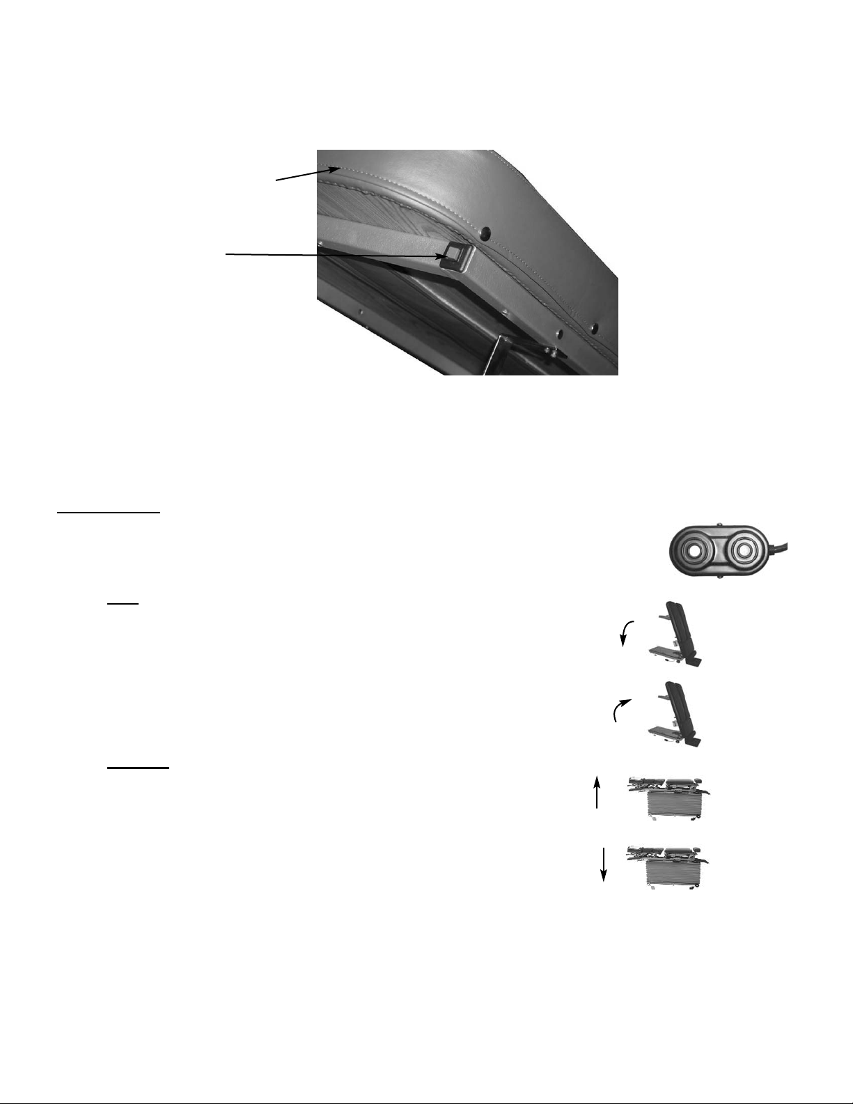
In the manual mode; the height of the table can be adjusted with the foot pedal or with
the directional switches on the console. The table will stop when the pedal or panel
switch is released.
Semi Auto Mode ( Light- Blinks) - The semi-auto mode is indicated by a blinking green light. The foot pedal or
directional switches on the console must be held down for the table operate.
Only when the table reaches it’s preselected height,or the operator releases the
switch will the table stop.
Auto Mode (Light-on)- Pressing the mode switch (No. 2) so that the light emits a continuous green light, indicates
the table is set in the auto mode. In this mode,a console or pedal switch can be activated and
released. The table will continue to run thought it’s activated mode (load, unload, or height
selection), or can be stopped by pressing the switch again.
Unload Switch (No. 3)
The Lower (Elev.) / Tilt Switch (No. 3) lowers the table from a horizontal position and
raises it to a hylo Vertical position.
Load Switch (No. 4)
The Lower (Tilt) / Elevate Switch (No. 4) lowers the table from a Vertical position to the
horizontal position.
Up/Down Switch (No. 5)
Used for adjusting the height tables elevation hei turning the beeper sound on or off.
#1 Height Select
#3 Unload Switch
Horz. Down / Tilt Up Switch
#4 Load Switch
Horz. up / Tilt Down Switch
#5 Elevation Height
Up / Down
#2 Mode Switch
Auto / Semi Auto / Manual
Page 5
#6 Speed Control
Elevation / Tilt

#6 Speed Control
Elevation / Tilt
#7 Mute/Calibration Button
Mute Button
The mute button is a on and off switch, used to control the audable beeper of the control switches. Pushing the
button and releasing will turn the beeper sound on or off .
Speed Control: Elevation / Tilt (No. 6)
Speed control knob (#6) is mounted on the left side of the Height select box. This Is the speed adjustment for
elevation up & down and the table’s tilt up & down. Adjusting the speed for one function, will equally
adjust the speed for the other three functions equally.
a. Turn clockwise - Increase speed
b. Turn counter clockwise - Decrease speed
Table Calibration (No.7)
Normally the table has to be calibrated only if the Logic board is replaced or the table is moved.
Calibration could be affected when moving and when not setting in a level position.
Calibration of the table is a procedure in which the table goes thru a complete cycle of elevating and tilting
operations. This is approximately a ten minute duration.
To start the table’s calibration, press and hold the Calibration button (No. 7), until all of the height switch lights
blink on simultaneously. Once the light’s go off, activate the Load button (orange) and Down button (green)
at the same time. This will activate the table to run thru it’s elevation and tilt operations for approximately
ten minutes. On completion, the table will end in the top tilt position. At this point a double peep tone
will be activated. This finalizes the table’s calibration, and the table is ready to resume operation.
Down Button (green)
Load Button (orange)
Height Select Panel
Page 6
Up Button (blue)
Unload button (yellow)

Page 7
Height Default Setting
The table’s elevation height is set at a default of twenty-two inches from the factory. The setting default automatically
brings the table to the same set height when turned on each time. The Height Default can be recalibrated to meet
the needs of a doctor’s personal heigth preference.
1.) Press the Mute / Calibration button (#7, page 15) on the side of the Height Select box. Hold until all of the height switch
lights are blinking, then press a selected height button to be the new default setting.
Mode Default Setting
Mode settings is a selection of manual / semi auto / auto operation modes (#2, page 13) the table runs in. The default
setting can be set in manual or auto mode.
1.) Press the Mute / Calibration button (#7, page 15) on the side of the Height Select box. Hold until all of the height switch
lights are blinking, then press manual / semi auto / auto button to set the default setting to manual or auto.

GALAXY 906HS
Parts & Assembly Section

ACTIVATOR CUSHION SETS
1
2
DP Pelvic / Std. Ankle
DP Pelvic / Wedge Ankle
698597 28” ACT. HYLO 698595 28” ACT. HYLO
698609 26” ACT. HYLO 698594 26” ACT. HYLO
Page 8

ACTIVATOR 906
TILT FRAME FRAME ASSEMBLY
(601410)
1
8
3
4
5
6
7
10
9
7
2
ITEM PART N0. DESCRIPTION QTY.
1 55400 TILT FRAME ASSEMBLY 1
2 21310 CAP NUT, ½-20UNC 2
3 20230 ELEVATOR BOLT, 5/16-18 UNC X 1 ¼ 1
4 22820 ROLLER BEARING 2
5 20532 HEX. HD. BOLT, ½-20UNC X 2 2
6 53221 SADDLE FRAME ASSEMBLY 1
7 22920 BUSHING FLANGE, ¾ ID X 7/8 OD 4
8 53383 CONNECTING PIN, ¾ RD X 6 1
9 53377 CONNECTING PIN, ¾ RD. X 8 1
10 21110 HEX NUT, 5/16-18 UNC 2
Page 9

1
2
3
4
5
7
8
9
10
10
14
5
13
12
12
515
6
8
5
14
16
17
18 19
19
18
17
16
ITEM PART N0. DESCRIPTION QTY.
1 53225 BASE FRAME ASS’Y 1
2 53296 AXLE STUD, 3/8 RD X 1 3/8 4
3 22904 FLANGE BUSHING, ¾ ID 4
4 20021 SOCKET HD BOLT, ¼-20UNC X 1 4
5 21955 PLASTIC WASHER, .765 IDX 1¼ OD 6
6 53223 ROCKER ARM ASSEMBLY 1
7 53222 ROCKER ARM ASSEMBLY 1
8 21305 HEX NUT, ½-13 UNC 2
9 22113 SET SCREW, ¼-20 UNC X 3/8 4
10 53224 DRIVER ARM ASSEMBLY 1
11 22792 ROLLER BEARING, 5/8 ID 2
12 20208 SOCKET HD. BOLT, ½-13 UNC 2
13 21959 PLASTIC WASHER, .665 ID X 1 ½ OD 2
14 22110 SET SCREW, ¼-20 UNC X ¼ 4
15 22091 SET SCREW, #10-24 UNC X 3/16 2
16 20544 HEX HD. BOLT, ½-20 UNF X 2 ½ 2
17 21910 FLAT WASHER, ½ ID X 1.00 OD 2
18 56114 WHEEL BUSHING, 2
19 56113 WHEEL 2
20 53390 LEVELING POST 2
21 21110 JAM NUT, 5/16-18UNC 2
22 20230 ELEVATOR BOLT, 5/16-18 UNC 2
23 53317 CLIP, BELLOWS 2
24 35930 CLIP, PLASTIC 2
25 21995 MACHINE SCREW, # 10-24 UNC X 1/2 2
26 20215 HEX HD. BOLT, 5/16-18 UNC X 3/4 2
27 21755 WASHER, 5/16 ID 2
906 BASE FRAME ASSEMBLY
11
20
21
22
23
23
24
4
25
25
24
26
27
Page 10
4

ITEM PART N0. DESCRIPTION QTY.
1 40410 ANKLE REST CUSHION 1
2 56507 BASE PLATE 1
3 30774 COMPRESSION SPRING 1
4 56519 LOCK HANDLE 1
5 56525 GUIDE BLOCK 1
6 56518 GUIDE ROD 2
7 22468 SCREW, WOOD, RD HEAD, #10 X 7/8 6
8 24236 GUARD, TEE HANDLE 1
9 22610 PIN, CLEVIS, 5/16 X 7/8 1
10 56539 GUIDE BLOCK 1
11 22640 COTTER PIN 1
12 21010 NUT, HEX, ¼ - 20 UNC 1
13 20002 BOLT, SOCKET, SHOULDER, ¼ - 20 UNC X ¾ 2
14 56512 LINKAGE ARM ASSEMBLY 2
15 22660 ROLL PIN, 1/8 X 5/8 1
16 52190 EXTENSION ROD 1
17 24415 PLASTIC CAP 1
18 22615 PIN, CLEVIS, 5/16 X 2 2
19 22110 SET SCREW, ¼ - 20 UNC X ¼ 3
20 21710 WASHER, FLAT, 5/16 ID 1
21 21760 WASHER, FLAT, PLASTIC, 5/16 ID X ½ OD 1
1
23 21
2
18
7
14
18
15
22
3
19 8
4
517
16
12
6
6
10
9
13
19
22
ANKLE REST
ADJUSTABLE HEIGHT
Page 11

FOOT STAND ASSEMBLY
ITEM PART N0. DESCRIPTION QTY.
1 611130 FOOT PLATE ASS’Y 1
2 22013 BUTTON HD, MACHINE SCREW, ¼-20 UNC X ½ 4
3 20613 SOCKET HC. SHLD. BOLT, 5/8 –11 UNC X ¾ 2
4 53313 FOOT STAND PIVOT FRAME ASS’Y 1
5 22520 ROLLER BEARING ½ ID 1
6 53259 BUSHING, 3/8 ID X ½ OD X .375 1
7 53399 PIN, 3/8 RD X 1.23 3
8 53305 LINKAGE BAR 1
9 53306 PUSH ROD, 1 ¼ RD X 13 1
10 22791 ROLLER BEARING 1
1
2
34
35
10
9
7
7
8
6
Page 12

Page 13
BELLOWS MOTOR COVER ASSEMBLY
1
2
2
3
4
5
6
7
8
9
11
12
14
15
13
16
11
13
15
14
7
9
14
15
7
9
8
17
17
12
9
10
11
8
15
10
17
ITEM PART N0. DESCRIPTION QTY.
1 699220 BELLOWS COVER 1
2 53317 BRACKET BELLOWS 2
3 699080 COVER, CIRCUIT BOARD 1
4 699015 COVER, MOTOR 1
5 35940 CLIP, NYLON 2
6 53342 RAIL, BELLOWS 2
7 22605 MALE SNAP 8
8 21420 HEX NUT, #8-32 UNC 8
9 21105 CAP NUT, #8-32 UNC 8
10 53386 CONNECTING PIN, ¼ RD 6
11 53387 GUIDE BUSHING, NYLON 6
12 22913 COLLAR, SET, ½ ID X 1 OD 2
13 53341 HANGER ROD 2
14 53340 SUPPORT ROD, ½ RD X 3.625 4
15 20022 HEX HD BOLT, ¼-20 UNC X 1 8
16 699013 COVER, ELECTRICAL ASS’Y 1
17 36970 VENT CAP 1
( 616010)
16
10
10

HYDRAULICS
(613211)
1
2
3
4
5
6
2
24
7
8
24
12
12
9
9
11
11
10
13
13
15
19
10
7
16 17 18
ITEM PART N0. DESCRIPTION QTY.
1 624736 TILT CYLINDER ASS’Y 1
2 56971 STOP COLLAR 7/16 ID 2
3 30782 COMPRESSION SPRING ½ ID X 6 1
4 53393 EYE-ROD, 7/16RD. X 13 11/16 1
5 53380 EYE-ROD, 7/16. X 15 1/16 1
6 53254 COMPRESSION SPRING, ½ ID X 5 1
7 45223 HYDRAULIC HOSE, 3/16 X 13 1
8 623559 MOTOR ASS’Y 1
9 45296 HYDRAULIC HOSE, 3/16 X 27-45 deg. 1
10 45305 HYDRAULIC HOSE, 3/16 X 35- 45 deg. 1
11 45298 HYDRAULIC HOSE, 3/16 X 29 1
12 23641 LEGRIS HOSE, ¼ X 48 1
13 45290 HYDRAULIC HOSE, 3/16 X 22 1
14 624942 ELEVATION CYLINDER 1
15 623416 LOWER SEQUENCE BLOCK 1
16 20052 HEX HD. BOLT, ¼-20 UNC X 1 ¾ 2
17 21630 STAR WASHER, ¼ ID X ½ OD 2
18 21620 FLAT WASHER, ¼ ID X ½ OD 2
19 623418 UPPER VALVE BLOCK ASS’Y 1
20 20010 HEX. HD. BOLT, ¼-20UNC X ¾ 2
21 53382 PIN, TILT CYL BARREL. ½ RD X 4 ¼ 1
22 22160 SET SCREW, ¼-28 UNF X ¼ 2
23 22673 COTTER PIN, 1/8 X 1 3
24 23642 LEGRIS HOSE, ¼ X 55 1
25 53395 UPPER PIN, TILT CYL. ½ X 4 ½ 1
26 21322 CASTLED NUT, ½-20 UNC 2
27 22679 PIN, ELEV. CYL BASE, ½ RD X 3 ½ 1
28 22090 SET SCREW, #10-32 UNF X 3/16 1
29 50356 HEX. BOLT ½-28 UNF X 2 1
30 21915 WASHER, PLASTIC, 9/16 ID X 11/16 OD 3
20
27 29
14
26
23
23
21
22
30
28
25 23
Page 14

2
3
4
8
7
6
5
5
2
9
10
20
11
15
8
16
4
12
13
14
7
21
22
23
20
22
17
16
8
18
8
28
27
16
22
31
30
29
26
25
32
24
ELECTRICAL ASSEMBLY
(614391)
Page 15
1

ITEM PART N0. DESCRIPTION QTY.
1 45039 CIRCUIT BOARD ASS’Y, IO CONTROL 1
2 45158 CABLE ASS’Y, LOWER SOLNOID BLOCK 1
3 45156 CABLE ASS’Y, 24V 1
4 44226 CABLE ASS’Y, UPPER SOLNOID BLOCK 1
5 43980 HEIGHT SENSOR ASS’Y 1
6 44235 CABLE ASS’Y, TILT SENSOR 1
7 44234 CABLE ASS’Y, HS BOX 1
8 45075 WIRE HARNESS ASS’Y, IO CONTROL 1
9 45044 CONTROL PANEL 1
10 44231 CABLE ASS’Y, TILT LIMIT 1
11 44048 TILT LIMIT SWITCH 1
12 52054 CONTROL BOX 1
13 55387 HINGE ASS’Y 1
14 55386 SPACER 1
15 55924 CONTACT BAR 1
16 38040 LIMIT SWITCH 3
17 53331 L-BRACKET 1
18 37900 HEX SPACER, #6-32UNC X ½ 12
19 21972 PAN HD SCREW, #6-32UNC X ¼ 4
20 21975 PAN HD SCREW, #6-32UNC X ½ 5
21 43981 TILT SENSOR ASS’Y 1
22 21982 PAN HD MACHINE SCREW, #8-32UNC X ½ 6
23 45076 WIRE HARNESS ASS’Y, UPPER STRIP 1
24 36172 POWER CORD 1
25a 36377 FUSE DRAWER (gray, 110v) 1
25b 33678 FUSE DRAWER (black, 220v, 100v) 1
26a 36370 FUSE (110V) 1
26b 36353 FUSE (220 V) 1
26c 36371 FUSE (100V) 1
27 53398 SWITCH BRACKET 1
28 44225 CABLE ASS’Y, EXT-RET. SWITCH 1
29 44920 SAFTEY TILT SWITCH 1
30 45016 POWER CHASSIS ASS’Y 1
31 21995 PAN HD SCREW, #10-24UNC X ½ 2
32 44217 POWER ENTRY MODULE ASS’Y 1
ELECTRICAL ASSEMBLY
((614391)
Page 16

Page 17
1
2
3
4
5
6
7
7
8
25
26
27
10
9
1030 31
32
11
9
10 13
12
14
15
17 16
18
19
17
34
24
10
25
26
27
28
33
36
37
36
35
38
29
40
39
38
23
22
21
20
33
17
PELVIC T-DROP ASSEMBLY
(619290)
2
41
Table of contents
Other Lloyd Medical Equipment manuals
Popular Medical Equipment manuals by other brands

ViOptix
ViOptix T.Ox OXY-2-USM-1 Operator's manual

IMP
IMP De Mayo Hip Positioner System STANDARD Setup instructions

Ambu
Ambu aBox 2 Instructions for use

GETINGE GROUP
GETINGE GROUP Maquet CARDIOSAVE IABP Quick reference guide

Guardian
Guardian Homecare Bed 4" Extender User instruction manual & warranty

tecnodent
tecnodent SERENITY NEXT operating instructions