Lloyd GALAXY McMANIS HYLO User manual


CONTENTS
OPERATIONS PAGE
Safety and Maintenance................................. 1 - 2
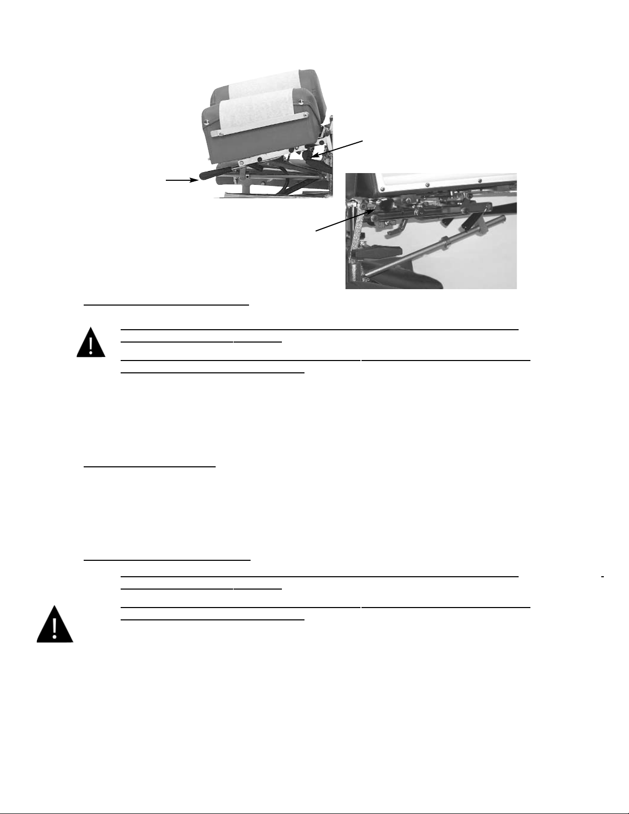
Head Rest Cushion......................................... 3 - 7
Chest Cushion................................................. 8
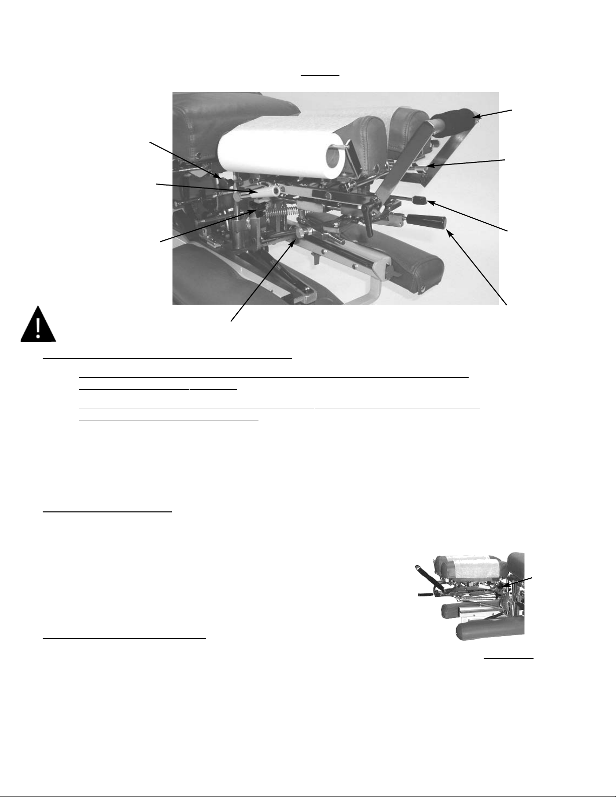
Manual & Automatic Drops........................... 9 - 11
Head & Chest Extension / Retraction............ 11
Pelvic Cushion - Flexion............................... 12 - 16
Pelvic Lateral Side Bending.......................... 16
Pelvic Rotation & Telescoping T-Bar........... 17
Ankle Rest & Lumbar Extension................. 18
Control / Indicator Box................................. 19 - 20
Tilt Safeguard................................................ 20
Pelvic Extension /Retraction Switch............. 21
Foot Pedal Control........................................ 21
Master Power Switch & Fuses...................... 22
PARTS / ASSEMBLY PAGE
22” Frame .................................................... 23 - 24
24” Frame..................................................... 25 - 26
Deluxe Head Frame...................................... 27
Deluxe Head Cushion................................... 28
Deluxe Head I-Frame.................................... 29 - 30
Chest Cushion Assembly............................... 31 -32
PARTS / ASSEMBLY PAGE
Pelvic Cushion Non-Rotation....................... 33
Telescoping T-Bar......................................... 34
Ankle Rest Adjustable Height...................... 35
Foot Plate Assembly...................................... 36 - 37
Covers ........................................................... 38
Hydraulics ..................................................... 39 - 42
Electrical Assembly...................................... 43 - 44
Straight Drop Head....................................... 45 - 46
Forward Motion Drop Head......................... 47 - 48
Flexion Head Cushion Assembly................. 49 - 50
Flexion Head - Shuttle Assembly................. 51 - 52
Flexion Head - Slide Frame.......................... 53 - 54
Flexion Head Rotation Block....................... 55 - 56
T - Drop Chest .............................................. 57 - 58
Drop Chest & Lumbar.................................. 59 - 60
Rotation Drop Chest Frame.......................... 61 - 62
Rotation Drop Chest Cushion ...................... 63 - 64
T-Drop Pelvic (Non Rotation)....................... 65 - 66
T- Drop Pelvic (Rotation)........................... 67 -68
Electrical Diagram ....................................... 69-74
Table Serial Number

WELCOME!!
Lloyd Table Company, a proud supporter of today’s chiropractic, has established the finest line of chiropractic tables
in the world. Table products unique in versaltilty and function, designed to meet your needs.
Concerned for a safe working and treatment environment, Lloyd Table Company asks that you follow the safety tips below.
*Be aware of Caution and Warning labels posted throughout the table before operating any functions.
*Everyone operating the table needs to read the manual and familiarize themselves with all its functions before
operating table with patient on it.
*The McManis pelvic operation is only to be operated by a professional practitioner, educated in the procedure of
the flexion distraction and traction on the lower back and spine.
*A patient should never be unattended, when lying on the table.
NEVER LEAVE A PATIENT ON THE TABLE UNATTENDED!
Secure the pelvic cushion into all lock positions before allowing patient on or off the table.
(See pages 13,16 & 17 to lock pelvic rotation, pelvic flexion, and pelvic side bending)
*The patient should be positioned at or near the center of the table with
arms and hands placed on top of armrest cushions.
*There should be no more than one operator at the controls.
*The pressure gauge reading should never exceed 800 PSI or drop below 300 PSI
*Check the tension on all drops before adjusting the patient. (See Page 9)
SAFETY
Page 1

MAINTENANCE
The following steps should be performed on a regular basis to maintain your Lloyd table in a smooth operating condition and to
assure its long life and top quality appearance.
*An initial inspection and periodic future inspections should be made to insure that nuts and bolts have not loosened
in shipping or during daily operations.
*Your Lloyd table should be lubricated every six months. Parts to be lubricated are all frame pivot points,
and metal to metal sliding mechanisms. (DO NOT LUBRICATE FRICTION LOCKS)
*The cushions should be cleaned daily with a mild soap & warm water solution to remove body oils.
Rinsed & dried. DO NOT USE VINYL CLEANERS TO CLEAN CUSHIONS!!
*Chrome parts should be cleaned on a weekly basis for appearance.
*The hydraulic fluid recommended for the pump, is a lubriplate HO1or hydraulic jack oil,and should be
checked on a yearly basis.
*Perform periodic inspections for oil leaks or drips.
*The fluid level in the pump’s reservoir tank should measure 1-3/4 of an inch from full. This measurement is taken
when the pelvic cushion is in the down position, the pressure gauge is released back to zero, table is in lowest
elevated position and fully shortened or retracted.
Page 2

The following sections provide explanations on the operation of your Lloyd table. All references to right and left, will be in relation-
ship to your view, as you face table from the foot end. All references to the front will refer to the head end of the table. Those to the
rear will refer to the foot end.
Head Cushion
The head cushion is designed to provide a multitude of positions & operations though our standard
Deluxe Headpiece and optional Total Dimension FlexionTM Headpieces.
Standard Deluxe Headpiece
#5 Center Bar
#4 Paper Hanger
#2 Elevation Knob
#3 Face Opening
Lever
#1 Tilting Lock Handle
#6 Paper Cutting Bar
To Raise the tilting feature on the Deluxe Headpiece:
1. Lift on the bottom front edges of the cushion
2. Release at the desired height, the cushion will automatically lock into position.
To Lower the tilting feature on the Deluxe Headpiece:
1. Support the front corner of the cushion.
2. Lift the Locking Handle (No. 1) to release.
3. Gently lower the cushion to the desired height.
4. Release the lock handle first and then the cushion to lock.
WARNING: TO AVOID INJURIES WHEN RAISING OR LOWERING HEAD
CUSHIONS, BE SURE TO HAVE A PROPER HOLD ON THE CUSHION BEFORE
RELEASING THE ELEVATING HANDLE (NO. 2).
Page 3

Standard - Deluxe Head
To Elevate the Head Cushion
1. The head cushion is assisted by a gas shock in raising the cushion. With a hand supporting the head cushion,
turn the Elevation Knob (No. 2) on either side of the table toward the foot end of the table to unlock.
When the desired height is determined simply release the Elevation Knob (No. 2) to lock.
To Lower the Head Cushion
1. Turn the Elevation Knob toward the foot end of the table to unlock. While unlocked push down on the cushion
to lower. When the desired height is determined simply rotate the Elevation Knob (No. 2) down to lock.
Face Opening Adjustment
1. The Head Cushion’s face opening can be opened or closed to adjust for comfort with the Face Opening Lever
(No. 3). By Pushing slightly down on the Face Opening Lever, slide side to side adjusting the face opening.
The Face Opening Lever must be released in one of eight positions to lock the cushions in place.
Paper Roll
The paper roll mounts conveniently inside the right-hand cushion.
Replacing the Paper Roll
1. Remove the paper hanger tension rod (No. 4) by compressing ends of the rod horizontally.
This will allow you to slide one end out, to remove the paper roll tube.
2. Slide a new paper roll on the tension rod so that it rolls off the bottom side.
Compress the rod ends horizontally and set inside the head cushion.
3. Swing the Center Bar (No. 5, Page 3) and Outside Cutting Bar (No. 6, Page 3) up.
Route paper over the cushions and down between the two outside cutting bars.
Return both bars to their original position.
4. Trim the paper by supporting the paper cutting bar with one hand and pulling the paper up along the bar’s edge.
Page 4

Optional - Deluxe Head with Drops
#7 Cocking Handle
#8 Tension Knob
#9 Selector Knob
(Right Side of Table)
Operating the Straight / Toggle Drop:
CAUTION: THE DROP CUSHION TENSION SHOULD BE CHECKED AND TESTED
BEFORE ADJUSTING A PATIENT.
NOTE - DROP SHOULD BE IN DOWN / DEACTIVATED POSITION BEFORE MOVING
SELECTOR KNOB (NO. 9) IN OR OUT.
1. To engage the Straight / Toggle Drop head, pull the selector knob (No. 9) out about half an inch.
2. Push down on the Cocking Handle (No. 7) until the head cushion is cocked into its top position.
3. Once cocked, test the drop by pushing down on the cushion. If the cushion drops too easily or too hard,
adjust the tension with the Tension Knob (No. 8).
Operating The Tension Knob:
1. The tension is adjusted by turning the tension knob (No. 8) in a clockwise and counter-clockwise
direction.
A. Clockwise - Increases tension
B. Counterclockwise - Decreases tension
Operating the Forward Motion Drop:
CAUTION: THE DROP CUSHION TENSION SHOULD BE CHECKED AND TESTED
BEFORE ADJUSTING A PATIENT.
NOTE - DROP SHOULD BE IN DOWN / DEACTIVATED POSITION BEFORE MOVING
SELECTOR KNOB (NO. 9) IN OR OUT.
1. The Selector Knob (No. 9) is to be pushed in, to engage the forward motion drop.
2. Push down on the Cocking Handle (No. 7) to raise into its cocked position.
3. Once cocked, test the drop by pushing down on the cushion, and adjust the tension
(see above Operating the Tension Knob section).
Page 5

Optional - Total Dimension Flexion HeadTM
Left Side
#1 Selector Knob
#2 Cocking Handle
#4 Traction Release
Knob
#3 Lateral Side Bending
Release Knob
#8 Flexion Assist
Handle
#6 Rotation
Release Knob
#5 Flexion / Tilt
Knob
Forward & Straight / Toggle Drop Operation Instructions
CAUTION: THE DROP CUSHION TENSION SHOULD BE CHECKED AND TESTED
BEFORE ADJUSTING A PATIENT.
NOTE - DROP SHOULD BE IN DOWN / DEACTIVATED POSITION BEFORE MOVING
SELECTOR KNOB (NO. 9) IN OR OUT.
1. To engage the Straight / Toggle Drop head, pull the selector knob (No. 1) out about half an inch.
2. Push down on the Cocking Handle (No. 2) until the head cushion is cocked into its top position.
3. Once cocked, test the drop by pushing down on the cushion. If the cushion drops too easily or too hard, adjust
the tension with the Tension Knob (No. 9).
Operating The Tension Knob:
1. The tension is adjusted by turning the tension knob (No. 9) in a clockwise and counterclockwise direction.
A. Clockwise - Increases tension
B. Counterclockwise - Decreases tension
Operating the Forward Motion Drop:
1. The Selector Knob (No. 1) is to be pushed in, to engage the forward motion drop.
2. Push down on the Cocking Handle (No. 2) to raise the drop cushion to its cocked position.
3. Once cocked, test the drop by pushing down on the cushion. If the cushion drops too easily or too hard, adjust
the tension with the Tension Knob (No. 9).
Page 6
#9 Tension
Knob
Right Side
#7 Face Opening
Lever

Lateral Side Bending
1. To unlock the Lateral Side Bending Feature rotate the Lateral Side Bending Release Knob (No. 3) clockwise
(from left side of table).
2. Turn the Lateral Side Bending Release Knob (No. 3) counterclockwise to lock headpiece in desired position
(from left side of table).
CAUTION: MAKE SURE THE HEADPIECE IS LOCKED BEFORE ALLOWING A
PATIENT ON OR OFF THE TABLE.
Manual Traction
1. To unlock the manual traction feature simply pull and twist the Traction Release Knob (No. 4)
1/4 of a turn clockwise or counterclockwise.
2. When unlocked the headpiece will glide forward and backward.
3. To lock the manual traction twist the Traction Release Knob (No. 4) 1/4 turn counterclockwise or clockwise.
Manual Flexion Distraction
1. To unlock the manual flexion distraction locate the Flexion / Tilt Knob (No. 5) pull forward and twist 1/4 turn
counterclockwise.
2. Gently apply pressure down using the Flexion Assist Handle (No. 8).
3. To lock the manual flexion distraction twist the Flexion / Tilt Knob (No. 5) 1/4 turn clockwise and release to
engage lock.
Tilting Feature
1. To unlock the Tilting feature locate the Flexion / Tilt Knob (No. 5) while supporting the head cushion pull forward
and twist counterclockwise.
2. Once the desired angle is obtained, lock the headpiece simply by twisting the Flexion / Tilt Knob (No. 5)
clockwise and release.
Rotation Feature
1. To unlock the Rotation feature locate the Rotation Release Knob (No. 6) Pull toward the head of the table and twist
1/4 turn clockwise.
2. Gently move the headpiece with the Flexion Assist Handle (No. 8)
3. To lock the Rotation feature locate the Rotation Release Knob (No. 6) twist 1/4 turn counter clockwise and release.
Face Opening Adjustment
1. The Head Cushion’s Face Opening can be opened or closed to adjust for the comfort with the Face Opening Lever
(No. 7). By pushing slightly down on the Face Opening Lever, slide side to side adjusting the face opening.
The Face Opening Lever must be released in one of the eight positions to lock cushions in place.
Flexion Assist Handle
1. The Flexion Assist Handle (No. 8) has many functions including aiding with manual Cervical Flexion Distraction,
rotation, lateral side bending, and tilting the headpiece.
2. To adjust the Flexion Assist Handle to desired comfort twist the Flexion Assist Handle locking Knobs on both sides
of table. This will unlock the handle for adjustment. Twist in opposite direction to lock.
Optional - Total Dimension Flexion HeadTM
Page 7
WARNING: THE FOLLOWING CERVICAL OPERATIONS ARE ONLY TO BE OPERATED BY A
PROFESSIONAL PRACTITIONER, EDUCATED IN THE
PROCEDURE OF FLEXION-DISTRACTION AND TRACTION, ON THE SPINE.

Chest Cushion
The chest cushion is designed to accommodate large and small abdomen patients, along with the versatility of being
a stationary, Breakaway Cushion.
#1 Adjustable Chest Handle
#2 Spring Breakaway
Release Knob
Standard - Adjustable Tilting Chest
Tilting Chest Cushion Up
1. Lift the rear corners of the cushion.
2. Release the cushion when the desired angle is reached and the cushion will automatically lock into place.
Tilting Chest Cushion Down
1. Support the cushion at the rear corners.
2. Lift on the Adjustable Chest Handle (No. 1) to release the cushion.
3. Slide the cushion to desired angle.
4. Release the Adjustable Chest Handle (No. 1) first and then the cushion to lock into desired height.
Spring Breakaway Chest
To Unlock Spring Breakaway Chest Cushion
1. Pull on Spring Breakaway Knob (No. 2) (facing the right side of the table) to unlock.
2. The resulting floating effect will allow the cushion to gently drop under pressure and spring back
when released.
To Lock the Spring Breakaway Cushion
1. Push on Spring Breakaway Knob (No. 2) (facing the right side of the table) to lock.
Spring Breakaway will only lock in neutral position
To Increase or Decrease the Tension for Spring Breakaway
1. Rotate the Spring Breakaway Tension Knob (No. 3).
A. Left Side: Clockwise - Increase Tension Counterclockwise - Decrease Tension
B. Right Side: Clockwise - Decrease Tension Counterclockwise - Increase Tension
** (Reference- Turning towards the Foot end the tightens tension.)
#3 Spring Breakaway
Tension Knob
Page 8

Chest Cushion - Manual Drops
#1 Cocking Handle
#2 Tension Control Knob
Chest & Lumbar Drop - Manual
Cocking the Drop Chest or Lumbar Cushion
1. Pull up on the Cocking Handle (No. 1) to cock the desired drop cushion.
2. Adjust the tension on either side by turning the Tension Control Knob (No. 2)
Right side: Clockwise - Decreases Tension Counterclockwise - Increase Tension
Left Side: Clockwise - Increase Tension Counterclockwise - Decrease Tension
** (Reference - Turning towards the Foot end tightens tension.)
CAUTION: THE DROP CUSHION TENSION SHOULD BE CHECKED AND TESTED BEFORE
ADJUSTING PATIENT. KEEP FINGERS AWAY FROM BOTTOM OF CUSHION TO AVOID
PINCHING
#1 Cocking Handle
#2 Tension Control Knob
Pelvic Drop - Manual
Cocking the Drop Pelvic Cushion
1. Pull up on the Cocking Handle (No. 1) to cock the drop cushion.
2. Adjust the tension on either side by turning the Tension Control Knob (No. 2)
Right side: Clockwise - Decreases Tension Counterclockwise - Increase Tension
Left Side: Clockwise - Increase Tension Counterclockwise - Decrease Tension
** (Reference - Turning towards the Foot end tightens tension.)
CAUTION: THE DROP CUSHION TENSION SHOULD BE CHECKED AND TESTED BEFORE
ADJUSTING PATIENT. KEEP FINGERS AWAY FROM BOTTOM OF CUSHION TO AVOID
PINCHING
Pelvic Drop
Page 9
#2 Tension Control Knob

Cervical (Head Cushion) Drop - Automatic
To Cock the Cervical (Head Cushion) Drop:
1. Rotate the selector knob (No. 1) to “C” to select the Cervical (Head Cushion) drop.
2. Step on the white strip to activate the auto cocking drop.
CAUTION: THE DROP CUSHION TENSION SHOULD BE CHECKED AND TESTED BEFORE
ADJUSTING PATIENT. KEEP FINGERS AWAY FROM BOTTOM OF CUSHION TO AVOID
PINCHING.
3. Adjust the tension on the drop by turning the Tension Control Knob (Refer to Page 5 for Instructions).
To Cock the Dorsal (Chest Cushion) Drop:
1. Rotate the selector knob (No. 1) to “D” to select the Dorsal (Chest Cushion) drop.
2. Step on the white strip to activate the auto cocking drop.
CAUTION: THE DROP CUSHION TENSION SHOULD BE CHECKED AND TESTED BEFORE
ADJUSTING PATIENT. KEEP FINGERS AWAY FROM BOTTOM OF CUSHION TO AVOID
PINCHING.
3. Adjust the tension on the drop by turning the Tension Control Knob (Refer to Page 9 for Instructions).
To Cock the Lumber Cushion Drop:
1. Rotate the selector knob (No. 1) to “L” to select the Lumbar drop.
2. Step on the white strip to activate the auto cocking drop.
CAUTION: THE DROP CUSHION TENSION SHOULD BE CHECKED AND TESTED BEFORE
ADJUSTING PATIENT. KEEP FINGERS AWAY FROM BOTTOM OF CUSHION TO AVOID
PINCHING
.
3. Adjust the tension on the drop by turning the Tension Control Knob (Refer to Page 9 for Instructions)
Automatic Cocking Drops
#1 Automatic Drop
SELECTOR KNOB
Page 10

Automatic Cocking Drops
To Cock the Pelvic Cushion Drop:
1. Rotate the selector knob (No. 1) to “P” to select the Pelvic drop.
2. Step on the white strip to activate the auto cocking drop.
CAUTION: THE DROP CUSHION TENSION SHOULD BE CHECKED AND TESTED BEFORE
ADJUSTING PATIENT. KEEP FINGERS AWAY FROM BOTTOM OF CUSHION TO AVOID
PINCHING.
3. Adjust the tension on the drop by turning the Tension Control Knob (Refer to Page 9 for Instructions)
Note - Table is capable of performing a combination of drops - See Selector Knob Letter
Reference Chart Below.
Selector Knob Reference Chart
C - Cervical Drop DC - Dorsal & Cervical Drops
D - Dorsal Drop LD - Lumbar & Dorsal Drops
L - Lumbar Drop PL - Pelvic & Lumbar Drops
P - Pelvic Drop CP - Cervical & Pelvic Drops
Head & Chest Extension - Retraction Switch
#1 Head & Chest
Extension - Retraction Switch
To Adjust the Height of Table:
The table must be in the vertical (Tilt) position, while the patient is standing on the foot plate, the switch is located on the
frame underneath the left arm rest.
1. To extend the head and chest cushions, toggle switch towards the head end of the table.
2. To retract (shorten) the head and chest cushion, toggle switch towards the foot end of the table.
* Note - This Switch also deactivates the child safety feature.*
Page 11

Pelvic Cushion
Flexion - Distraction
#1 Up Speed Control
#2 Down Speed Control
#3 Flexion Lock Handle
(Yellow)
#4 Flexion Pressure Gauge
The Pelvic section is designed with the capability of Traction, Lateral Side Bending, Flexion, and optional Rotation
Manual Pelvic Flexion Distraction
THE PELVIC FLEXION PRESSURE SHOULD BE CHECKED ON THE GAUGE FOR
PROPER SUPPORT AND ADJUSTED BEFORE ALLOWING A PATIENT ON THE TABLE.
To Increase the Flexion Pressure:
1. Turn the Flexion Lock Handle (Yellow)(No. 3) up to unlock manual pelvic flexion. Activating the cord end of the
gray foot pedal will increase the flexion pressure.
2. Observe the Flexion Pressure Gauge (No. 4) CAUTION: DO NOT EXCEED 800 PSI
To Decrease the Flexion Pressure:
1. Turn the Flexion Lock Handle (Yellow)(No. 3) up to unlock manual pelvic flexion. Activating the cordless end of
the gray foot pedal will decrease the flexion pressure.
2. Pressure drop can be observed on the pressure gauge.
CAUTION: DO NOT REDUCE BELOW 300 PSI
WARNING: THE FOLLOWING PELVIC OPERATIONS ARE ONLY TO BE OPERAT-
ED BY A PROFESSIONAL PRACTITIONER, EDUCATED IN THE PROCEDURE OF
FLEXION - DISTRACTION AND TRACTION, ON THE LOWER BACK AND SPINE.
!!
Increase Pressure
Decrease Pressure
Page 12

Pelvic Cushion
Flexion - Distraction
Manual Flexion
BEFORE ENGAGING PELVIC FLEXION, BE SURE THE PRESSURE IS PROPERLYADJUSTED
TO SUPPORT PATIENT (SEE FLEXION PRESSURE PAGE 12).
1. Turn the Yellow Flexion Lock Handle (Page 12, No. 3) up to engage manual flexion. Simply
push down on the pelvic, ankle cushion, or optional T-Bar to achieve flexion. The Flexion
Pressure Gauge pressure should be adjusted to push the patient’s weight back up.
2. To bring the pelvic cushion back to its horizontal position, the operator simply has to let up on the cushion.
3. Once the pelvic cushion is level, turn the Yellow Flexion Lock Handle (Page 12, No. 3) down to
lock manual flexion.
BE SURE TO TURN THE YELLOW FLEXION LOCK HANDLE DOWN, LOCKING THE CUSHION IN
ITS HORIZONTAL POSITION, BEFORE ALLOWING A PATIENT ON OR OFF THE TABLE.
Semi-Automatic Flexion
The up/down motion of the pelvic cushion can also be performed semi-automatically with the gray foot pedal.
ALWAYS CHECK THE UP/DOWN SPEED OF THE PELVIC CUSHION BEFORE ADJUSTING THE
PATIENT. SEE FLEXION SPEED CONTROL BELOW).
1. To activate the semi-automatic flexion depress either side of the gray foot pedal.
Up Control: Press corded side of the gray foot pedal to bring cushion up.
Down Control: Press the cordless Side of the gray foot pedal to bring cushion down.
2. The table will not tilt unless the pelvic cushion is returned to the level position (See Page 19).
Up Control
Down Control
Semi-Automatic Flexion - Speed Control
Up Speed Control: Turn the Up Speed Control (Page 12, No. 1) clockwise to decrease the flexion
speed in the up motion.
Turn the Up Speed Control (Page 12, No. 1) counterclockwise to increase the
flexion speed in the up motion.
Down Speed Control: Turn the Down Speed Control (Page 12, No. 2) clockwise to decrease the
flexion speed in the down motion.
Turn the Down Speed Control (Page 12, No. 2) counterclockwise to increase
the flexion speed in the down motion.
Page 13

Pelvic Cushion
Flexion - Distraction
#9 Flexion Height
Adjustment - Up
#10 Flexion Height
Adjustment - Down
#8 Pelvic Extension
#7 Pelvic Retraction
#6 Reset Button
#2 Counter Load Button
#4 Auto Flexion Start Button
#5 Auto Flexion Stop Button
#1 Flexion Counter
#3 Counter Display
#12 Patient
Stop Switch
Auto Flexion Preliminary Check (Optional Feature)
The following steps should be checked before operating auto flexion:
1. The Flexion Lock Handle (Page 12, No. 3) must be in down position to operate auto flexion.
2. Pelvic Side Bending must be locked in the center of table (See Page 16).
3. Optional Pelvic Rotation must be locked into a non-rotated position (See Page 17).
4. Make sure to run a test, checking the flexion depth and speed before adjusting a patient.
ALWAYS CHECK THE UP/DOWN SPEED OF THE PELVIC CUSHION BEFORE ADJUSTING THE
PATIENT. SEE FLEXION SPEED CONTROL PAGE 12 & 13.
Auto Flexion Operation Instructions
The Auto Flexion Counter enables you to program the number of repetitions of Flexion - Distraction desired.
1. Spin the Flexion Counter (No. 1) to desired number of repetitions 01 thru 99.
2. Next, push the Counter Load Button (No. 2) to load the number of repetitions dialed.
3. Notice the number dialed now appears on Counter Display (No. 3).
4. After the number has been loaded push the Auto Flexion Start Button (No. 4)
5. The Auto Flexion Stop Button (#5) and Patient Stop Switch (#12) can be used as an emergency shut-off.
Once activated, the flexion cushion will stop instantly.
Reset Button
The Reset Button (No. 6) is used to discontinue the flexion motion, and to reset the counter back to zero.
When the Reset Button is pressed during the flexion motion, the table will continue through its cycle until it
reaches its top position, then stops.
Pelvic Cushion Extension & Retraction
1. To elongate the pelvic cushion simply press the Pelvic Extension (No. 8) button. Press until desired length is
obtained, and release.
2. To shorten the pelvic cushion press the Pelvic Retraction (No. 7) button. Press until desired length is obtained,
and release. (The table will not tilt unless the pelvic cushion is fully retracted - See Page 19)
Page 14

Pelvic Cushion
Flexion - Distraction
Adjusting the Depth of the Up & Down Position
ALWAYS CHECK THE UP/DOWN SPEED OF THE PELVIC CUSHION BEFORE ADJUSTING THE
PATIENT. SEE FLEXION SPEED CONTROL PAGE 12 & 13.
Fig. #1: When the Flexion Height Adjustment - Up & Down Knobs(Page 14, No. 9 & 10) are
turned clockwise to their maximum limit, the pelvic cushion travels to it’s maximum
flexion distance.
Fig. #2 As the Flexion Height Adjustment - Up knob (Page 14, No. 9) is turned in a counter
clockwise direction, the pelvic cushion will minimize it’s up travel. The result is a
shorter up stroke, keeping the pelvic cushion in the low side.
Fig. #3 As the Flexion Height Adjustment - Down knob (Page 14, No. 10) is turned in a count
counter-clockwise direction, the pelvic cushion will minimize it’s down travel.
The result is a shorter down stroke, keeping the pelvic cushion on the high side.
Overlap Indicator
The overlap indicator light shows that the operator has lapped the Up & Down Flexion Modes overone another.
Example:Both the Flexion Adjustment - Up & Down controls are turned to their maximum limit (MAX).
The pelvic flexion has been started, and you want to shorten up the stroke. You then turn the up control, back
in a counterclockwise direction. When the knob is turned back, the flexion stroke gets shorter and shorter.
eventually you turn the control knob to the point where the green indicator light comes on, and the flexion
stops.
This indicates that the up strokes have been shortened to the point where it converges with the down stroke,
causing the motion to halt. To restart the flexion, turn the Up control clockwise until the indicator light is off.
The same will occur when turning the down control too far counterclockwise, causing it to converge with the
up stroke.
Fig. #1 Fig. #2 Fig. #3
Overlap Indicator Light
Page 15

Pelvic Cushion
Flexion - Distraction
Page 16
Up Delay
Down Delay
Pelvic Lateral Side Bending
To Operate Lateral Side Bending Feature:
1. Turn the Lateral Side Bending Handle up, to allow the pelvic cushion to laterally bend
2. The cushion can be locked at various angles of side bending, laterally moving the cushion in position and locking the
handle down. (The table will not tilt with this handle in the unlocked position, or if cushion is not centered.)
Lateral Side Bending
Lock / Unlock Handle
Up Delay Feature
The Up delay adjustment knob controls the amount of time the pelvic cushion stays in the highest set position from
0 to 30 seconds. Simply turn the knob clockwise to increase the delay.
Down Delay Feature
The down delay adjustment knob controls the amount of time the pelvic cushion stays in the lowest set position from
0 to 30 seconds. Simply turn the knob clockwise to increase the delay.

Pelvic Rotation & T-Bar
#1 Rotation Lock Handle
Pelvic Rotation (Optional)
To Unlock the Pelvic Rotation
1. Support the edge of the pelvic cushion.
2. Pull up and slide the Rotation Lock Handle (No. 1) towards the rear of the table to unlock.
To lock the Pelvic Rotation
1. Place the Pelvic Cushion into it’s horizontal position.
2. Slide the Lock Handle (No. 1) forward to lock.
3. Table will not tilt if lock handle is not locked securely see page 19.
Telescoping T-Bar (Optional)
To Change the height of the T-bar
1. While T-Bar is revealed and locked into position simply pinch the red lever against the
T-Handle to elevate or lower. Release red lever when desired height is obtained.
To reveal Telescoping T-Bar
1. Simply pivot the handle up until it locks into place. (Fig. 1)
To hide Telescoping T-Bar
1. Pivot the T-Bar down until it is in full horizontal position. (Fig. 2)
Telescoping T-Bar
Fig. 1 Fig. 2
Page 17
Table of contents
Other Lloyd Medical Equipment manuals
Popular Medical Equipment manuals by other brands

Avedro
Avedro KXL System Operator's manual

MedRx
MedRx Avant Polar HIT installation manual

Wissner-Bosserhoff
Wissner-Bosserhoff sentida instruction manual

Apex Digital
Apex Digital DOMUS 3 instruction manual

Belmont
Belmont Phot-X II 303 installation instructions

Care of Sweden
Care of Sweden CuroCell S.A.M. PRO Instructions for use