manuals.online logo
Brands
  1. Home
  2. •
  3. Brands
  4. •
  5. Lock4Safe
  6. •
  7. Lock
  8. •
  9. Lock4Safe DUET DU4020 User manual

Lock4Safe DUET DU4020 User manual

DU40•20 Technical Manual EN 150624
© 2015 www.Lock4Safe.com Page 1 of 4
DUET
DU4020 / DU4050
Technical Description/Installation Instruction
Characteristics
The Duet © combines an electronic safe lock and a mechanical Combination lock in one housing. The
operator uses the advantages of both Systems. The lock has the standard mounting dimensions
(66,5x41mm) and can be mounted in all 4 mounting positions. (RH, LH, VU, VD)
The lock can be mounted in typical security containers.
Dimension: 85 mm x 61 mm x 37 mm. NOTE: Because of the electronics, the housing is 5-8 mm
thicker than a normal combination lock.
Lock bolt: 25mm x 8mm with 2 holes (ready to tap M4 if required). The throw is 8mm. Max bolt force
10N.
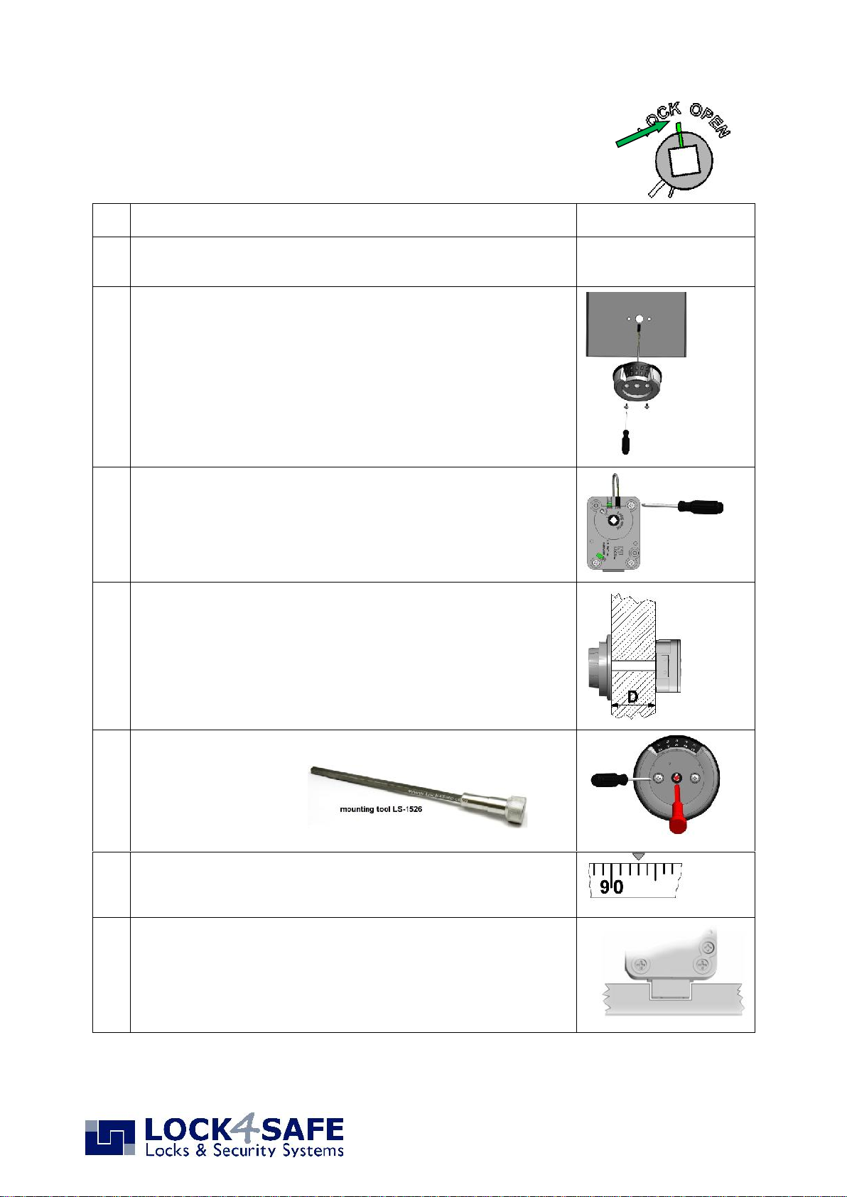
The lock may be mounted with the “DuetInput” DIxxxx as shown in this instruction or with any
approved entry unit and separate dial. The lock is driven by a 4,7 mm (3/16 inch) square spindle, a
spline key is not required. The distance between change and opening index is 8 ¼ numbers.
The construction of the security container needs to include protection against destructive force from
outside and should not give access to security relevant parts of the lock even with open door.
Installation dimensions
The diameter of the hole for cable and spindle should be minimal 8mm, maximal 12mm. Deburr the
spindle hole to avoid damage to the cable.
The cable does not move or wear when using the lock. However, the installer needs to take care that
the cable is not touching moving parts. For new constructions and if possible, it is advised to create a
separate hole for the cable. If spindle and cable share the same hole, use the plastic tube over the
spindle only to separate it from the cable.
DU40•20 Technical Manual EN 150624
© 2015 www.Lock4Safe.com Page 2 of 4
The Lock is delivered with the Bolt retracted and ready for
mounting. Do not move the cam (part with square hole) or the
bolt. During installation the bolt must stay in retracted position
and cam lined up as shown right.
1
Prepare the mounting and cable / spindle holes
2
Remove the small combination dial in the middle of the input unit
and remove the spacer ring. (do not throw away!)
3
Put the input electronic cable through the hole in the container door.
Be sure cable is inserted down into the slot in the back of the
keypad housing. Mount the input with two entry screws M4. Do not
tighten the screws yet.
4
Using the mounting screws, mount the lock in the correct position on
the inside of the safe door. Take note of any modifications that may
be needed to accommodate a relocker. Use Loctite to secure the
screws (approximately 3.5 Nm torque). Plug the four input’s prong
connector into the ENT slot of the lock. Thereafter, press the nose of
the plug lightly behind the metal housing so that it does not come
loose during use.
5
Cut the shaft for the mechanical dial and deburr both ends. Length:
41 mm + D (=door thickness). Insert the cut shaft into the square
hole of the DIAL.
6
Align the input unit (with mounting tool LS-1526) and tighten the 2
screws (hand tight)
7
For a first test, place the previously removed spacer (see 2)
between the dial and the keypad housing. With the bolt still
retracted, push the dial lightly into the keypad hole on approximately
number 93 of the dial.
8
Turn the dial LEFT to extend the bolt. In the LOCKED position, there
should be approximately 1 mm clearance between the lock bolt and
the cavity in the blocking bar of the boltwork. The lock bolt must
move freely into the cavity. Turn the dial several times to assure that
it turns freely.
DU40•20 Technical Manual EN 150624
© 2015 www.Lock4Safe.com Page 3 of 4
9
Open with factory code "50":
Turn LEFT and pass “50” four-times and stop exactly on the opening
mark the fifth time. Turn RIGHT until stop to open the lock. The dial
stops around number 93 on the opening mark.
Note: Due to installation tolerances it is possible that the code may
have shifted up to two numbers up or down. This shifting is normal
and will be eliminated once the code is re-set. If the lock does not
open on “50 “, try to open at “48” then “49”, “51” or “52”. Due to
these tolerances it is important to re-set the code after installation.
5x
10
Place 9V alkaline battery (Duracell ™) into the bottom compartment
of the input and close the compartment door.
To verify the electronics, turn the dial to the LEFT and stop at
number 60.
With DU4020: Enter factory code 1-2-3-4-5-6
With DU4050: Press 1
turn the dial within 3 seconds to the right to retract the bolt
11
Remove the dial (carefully) by pushing the shaft out from the lock
side. If you do not work with the mounting tool LS-1526, tighten the
screws now. (hand tight)
If spindle and cable share the same hole, use the plastic tube over
the spindle only to separate it from the cable.
12
Remove the spacer. With the lock in OPEN-position (bolt retracted)
hold the dial in a way that approximately “93” is lined up with the
dial’s opening mark and push it with light pressure into the lock.
The dial and shaft cannot be pulled back out as they are held by a
starlock washer.
13
Place the small plastic plug into the shaft hole at the rear of the lock
to retain the square shaft. Push all the way in with a screwdriver.
Set a new Factory Code (example: 10 20 30 40)
With door open, turn the bolt work and lock to locked position.
On the CHANGING INDEX dial the code at which the lock opened in Step 9.
Example: If the lock opens at “49”.
5 x LEFT until “49” stops exactly at the Changing Index
1. Carefully insert change key on the inside of the safe door.
Slightly wiggle if necessary.
2. Turn change key as shown clockwise to the stop (approx. 90 deg.)
Never apply excessive force
If change key cannot be inserted or turned, the correct code has not been dialed to
the Changing Index on the dial. Take out the key and dial the valid code again.
Change Keys
If installers use the
same change key to
set up several locks,
it is important to
inspect the change
key regular basis.
If the change key is
bend or shows signs
of wear it needs to
be replaced.
Otherwise the new
code will not be set
exactly as dialed.
DU40•20 Technical Manual EN 150624
© 2015 www.Lock4Safe.com Page 4 of 4
Now dial the factory code 10 20 30 40 on the Change Index
5 x Turn RIGHT, pass number “10” four times and stop exactly on the number on the
Changing Index the fifth time.
4 x Turn LEFT, pass second code number “20” three times and stop exactly on the
number on the Changing Index the fourth time.
3 x Turn RIGHT, pass third code number “30” twice and stop exactly on the number
on the Changing Index the third time.
2 x Turn LEFT, pass fourth code number “40” once and stop exactly on the number
on the Changing Index the second time.
When turning the dial, if a number is passed, start over at the beginning.
After the new Code is completely entered, turn change key LEFT and remove it. The new Code is
installed.
Try the new code several times (using Opening Index) before closing the door!
What if …
…accidentally the cam got moved before installation?
As long as the code has not been changed with the change key, the lock can be prepared for
mounting following the steps below:
1. Hold the lock so that you look at the cover and the bolt is to the right.
2. Turn the cam clockwise minimum 5 complete turns and stop when the cam is lined up as
shown in figure 1.
3. Turn cam counterclockwise until lock opens. The cam should be lined up with the “LOCK
OPEN” line on the cover (see figure 2).
Do not deviate from this instruction as it is part of the VdS certification.
5x
Fig 1
Fig 2

This manual suits for next models

1

Other Lock4Safe Lock manuals

Lock4Safe MiniTech User manual

Lock4Safe

Lock4Safe MiniTech User manual

Lock4Safe MiniTech User manual

Lock4Safe

Lock4Safe MiniTech User manual

Lock4Safe Pulse PRO User manual

Lock4Safe

Lock4Safe Pulse PRO User manual

Lock4Safe TouchManager User manual

Lock4Safe

Lock4Safe TouchManager User manual

Lock4Safe Pulse PRO User manual

Lock4Safe

Lock4Safe Pulse PRO User manual

Lock4Safe HOME2 User manual

Lock4Safe

Lock4Safe HOME2 User manual

Lock4Safe TechMaster User manual

Lock4Safe

Lock4Safe TechMaster User manual

Lock4Safe HOME10 User manual

Lock4Safe

Lock4Safe HOME10 User manual

Lock4Safe Pulse PRO User manual

Lock4Safe

Lock4Safe Pulse PRO User manual

Popular Lock manuals by other brands

GILGEN CLS manual

GILGEN

GILGEN CLS manual

Vanderbilt CD30 Codoor Configuration manual

Vanderbilt

Vanderbilt CD30 Codoor Configuration manual

Alarm Lock Trilogy DL3500 brochure

Alarm Lock

Alarm Lock Trilogy DL3500 brochure

Siegenia ALU Assembly instructions

Siegenia

Siegenia ALU Assembly instructions

PPA TRAVER UNO instruction manual

PPA

PPA TRAVER UNO instruction manual

HMF 3503 instruction manual

HMF

HMF 3503 instruction manual

Yakima 8002453 quick start guide

Yakima

Yakima 8002453 quick start guide

Ryobi RP4310 Operator's manual

Ryobi

Ryobi RP4310 Operator's manual

Digilock Numeris Versa Standard Guide

Digilock

Digilock Numeris Versa Standard Guide

D&D Technologies MagnaLatch MLSPS2 installation instructions

D&D Technologies

D&D Technologies MagnaLatch MLSPS2 installation instructions

Hafele Axis 231.98.330 operating instructions

Hafele

Hafele Axis 231.98.330 operating instructions

AmazonBasics B07T2C4791 manual

AmazonBasics

AmazonBasics B07T2C4791 manual

Carlon DH970 quick guide

Carlon

Carlon DH970 quick guide

CDVI V3E35R quick start guide

CDVI

CDVI V3E35R quick start guide

Yale YDG313 user guide

Yale

Yale YDG313 user guide

M-LOCKS ML6740 operating instructions

M-LOCKS

M-LOCKS ML6740 operating instructions

Allegion Olivari PT Series installation instructions

Allegion

Allegion Olivari PT Series installation instructions

Rockwell Automation 194R-P Series manual

Rockwell Automation

Rockwell Automation 194R-P Series manual

manuals.online logo
manuals.online logoBrands
  • About & Mission
  • Contact us
  • Privacy Policy
  • Terms and Conditions

Copyright 2025 Manuals.Online. All Rights Reserved.