Loctite PULSE EQ RC50 User manual

1
PULSE
EQ RC50 Integrated Dispenser
IDH 2814024
Operating Manual

2
Table of Contents
1Please Observe the Following...................................................................................................3
1.1 Emphasized Sections...........................................................................................................3
1.2 For Your Safety.....................................................................................................................3
1.3 Unpacking and Inspection ..................................................................................................4
1.4 Packing List...........................................................................................................................4
1.5 Features.................................................................................................................................4
1.6 Field of Application (Intended Use)...................................................................................5
2Description...................................................................................................................................6
2.1 Theory of Operation..................................................................................................................6
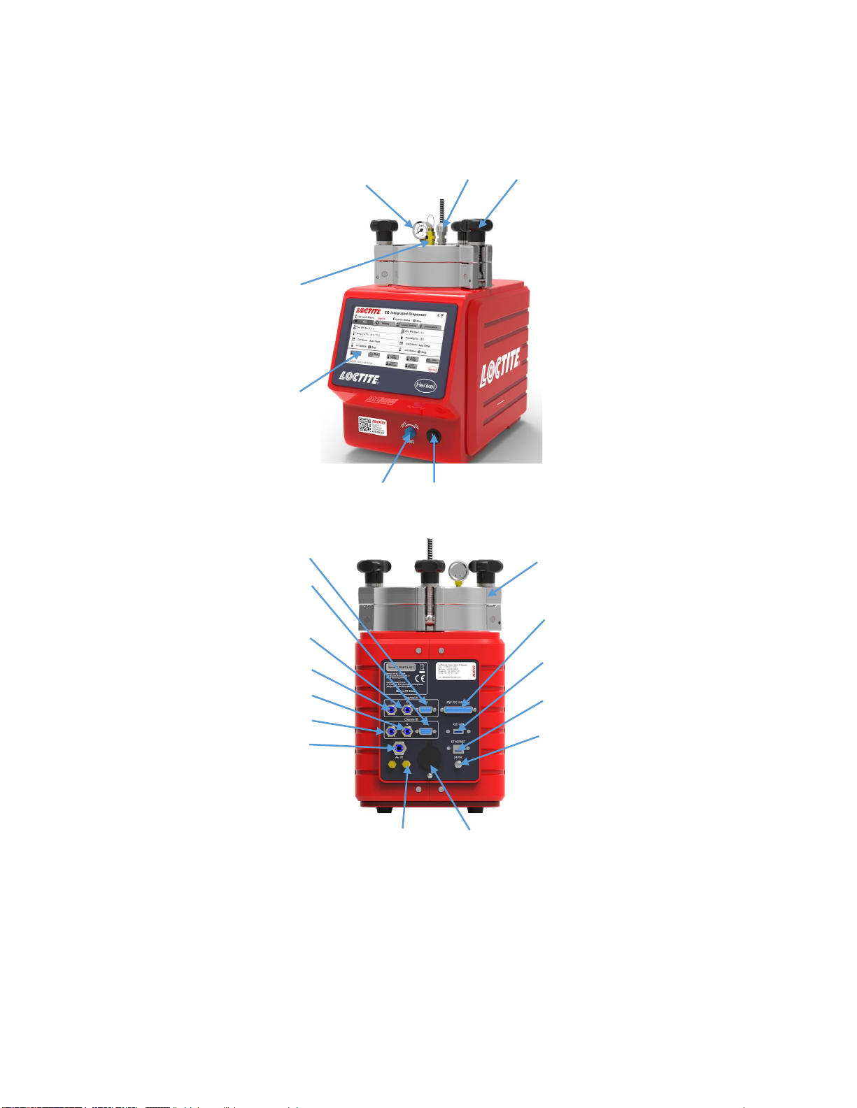
2.2 Display, operating elements and connections......................................................................7
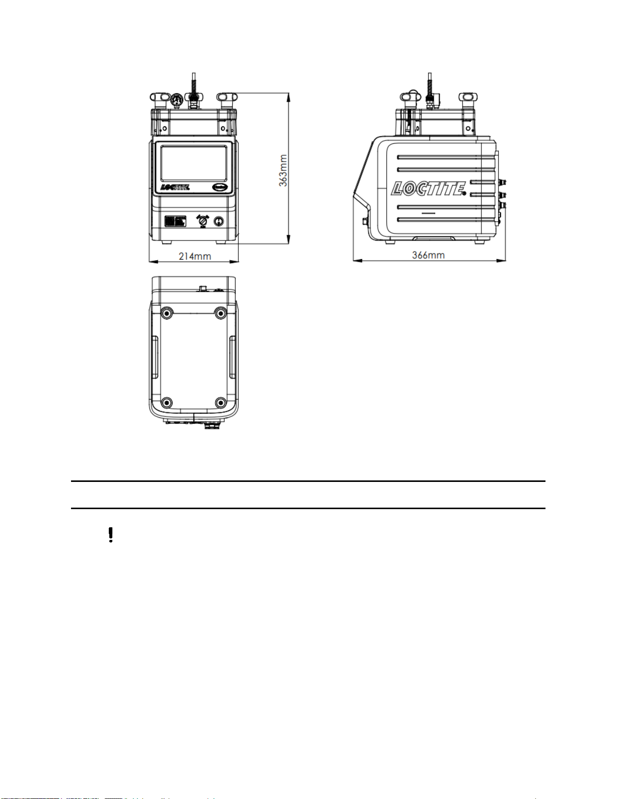
3Technical Data.............................................................................................................................8
4Installation....................................................................................................................................9
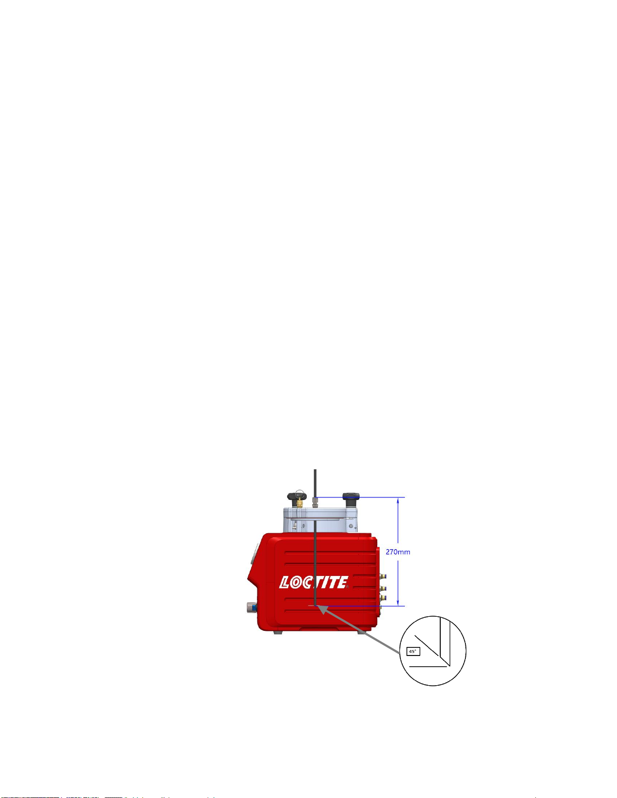
4.1 Environmental and Operating Conditions..............................................................................9
4.2 Connecting the Unit................................................................................................................10
4.3 Filling and Refilling the Product Reservoir..........................................................................11
5Operation....................................................................................................................................12
5.1 Turn on the Unit......................................................................................................................12
5.2 Main Page ................................................................................................................................12
5.3 Parameter Setting Page.........................................................................................................12
5.4 Communication Setting Page................................................................................................15
5.5 Equipment Info Page .............................................................................................................20
5.6 Set-up Configurations ...........................................................................................................21
5.7 Adjusting the Level Sensor....................................................................................................23
5.8 More Setting ...........................................................................................................................24
6Application Hints.......................................................................................................................27
7Troubleshooting.........................................................................................................................28

3
8Care and Maintenance .............................................................................................................31
9Accessories and Spare Parts...................................................................................................32
10 Diagrams ....................................................................................................................................33
11 Warranty.....................................................................................................................................36
12 Declaration of Conformity........................................................................................................37
1 Please Observe the Following
1.1 Emphasized Sections
Warning!
Refers to safety regulations and requires safety measures that protect the operator
or other persons from injury or danger to life.
Caution!
Emphasizes what must be done or avoided so that the unit or other property is not
damaged.
Notice:
A notice gives recommendations for better handling of the unit during operation or
adjustment as well as for service activities.
1.2 For Your Safety
For safe and successful operation of the unit, read these instructions
completely. If the instructions are not observed, the manufacturer can assume no
responsibility.
Do not expose the connecting cable to heat, oil, or sharp edges.
Make sure the Unit stands stable and secure.
Use only original equipment replacement parts.
Always disconnect the power supply before servicing the unit.

4
Observe general safety regulations for the handling of chemicals such as
Loctite®adhesives and sealants. Observe the manufacturer’s instructions as stated
in the Safety Data Sheet.
While under warranty, the unit may be repaired only by an authorized Loctite
service representative.
1.3 Unpacking and Inspection
Carefully unpack the Loctite®EQ RC50 Integrated Dispenser I-4.0 and examine the
items contained in the carton. Inspect the unit for any damage that might have
occurred in transit. If such damage has occurred, notify the carrier immediately.
Claims for damage must be made by the consignee to the carrier and should be
reported to the manufacturer.
1.4 Packing List
•EQ RC50 Integrated Dispenser I-4.0 x 1
•Equipment Manual x 1
•Universal Power AC Adapter with Cord x 1
•Reservoir Tank Fitting: ¼ inch NPT x ¼ Inch Tubing x 1
•Bottle Holder x 1
•¼” NPT to 6 mm inlet supply line connector x 1
•Anti-Bubbler Fitting and Tubing Kit x 1
•Footswitch x 1
•Bottle spacer disc x 1
1.5 Features
•Two independent digital timing channels that provide control of 2
pneumatic outputs
•Low level sensor alarm provides warning for adhesive bottle replacement
•Touch screen User Interface (UI) with color display and ease of use
•Two operating modes: Auto Timer and Continue mode.
•Equipped with a 0 to 7 bar (0-100psi) digital pressure regulator
•Integrated with I/O communication interface

5
•Powerful I4.0 function, to enable user to interact in real time via Wi-Fi,
Bluetooth, or Ethernet
1.6 Field of Application (Intended Use)
The Loctite EQ RC50 Integrated Dispenser I-4.0 combines both a controller and a
reservoir into a single unit. The controller provides 2 independent digital timing
channels that provide control of 2 pneumatic outputs. These outputs can be used to
control any Loctite automatic dispense valve or pneumatic hand-held applicator. The
controller can be actuated either by the start/stop button on the front touch panel, a
footswitch(included), or external start signal. It is capable of operating in a timed or
continue mode for dot or bead dispensing applications. The reservoir can
accommodate 50ml, 250ml, 500gram, 1 liter, and 2 kg adhesive packages which deliver
adhesive to dispensing valves. The reservoir is equipped with low level sensor which
can notify the operator that the adhesive package needs to be replace. The system
also includes an integrated industry 4.0 function that enables easy remote monitoring
by Wi-Fi, Bluetooth or ethernet.
With the EQ RC50 Integrated Dispenser I-4.0, anaerobic, UV Curing and cyanoacrylate
adhesive can be dispensed.
The capacity of the EQ RC50 Integrated Dispenser I-4.0 is:
-500 gr. bottle for CA Products -1 lb. bottle
-250 ml bottle for Anaerobics -1 Liter bottle
-Bottle with a φ124mm and -2kg bottle
a height of 250mm

6
2 Description
2.1 Theory of Operation
The EQ RC50 Integrated Dispenser I-4.0 is connected to an external pneumatic supply.
The system is equipped with a 0 to 7 bar (0-100psi) digital pressure regulator that
regulates the preset dispensing pressure of the reservoir and controls the dispensing
during the selected dispensing time.
An uncovered bottle of Loctite product is placed directly into the EQ RC50 Integrated
Dispenser I-4.0, the feedline is inserted into the product, and the reservoir lid is
clamped in place.
It is then pressurized using clean, filtered dry air. Air within the reservoir will push down
on the liquid in the bottle and force it through the product feed line to the dispensing
valve.
The amount of product dispensed is controlled by four main factors:
-Amount of pressure in the reservoir
-Length of time the dispensing valve remains open
-Valve stroke
-Dispensing needle size
Time Mode:
1. Press the footswitch/ manual button to activate the system
2. The dispensing timer will be activated and start to dispense with preset dispensing
time.
3. After the dispensing timer has reached the preset dispensing time, the dispensing
will be stopped.
Continue Mode:
1. Press the footswitch/ manual button to activate the system
2. The system will start to dispense, and the dispensing timer will start to count the
dispensing time.
3. Once the footswitch is released or press the manual button again, the dispensing
will stop.

7
2.2 Display, operating elements and connections
1. Power Switch ON/OFF
2. Air Pressure ON/OFF Switch
3. UI Screen
4. Valve Pressure Relief
7
6
5
4
3
2
1
9
8
19
15
14
13
16
17
18
20
21
10
11
12

8
5. Reservoir Pressure Gauge
6. Reservoir/Feedline Fitting
7. Reservoir Knob x 3
8. Reservoir Lid
9. Socket XS9 PLC Interface
10. Socket XS8 USB
11. ETHERNET
12. 24VDC Power In
13. Low Level Sensor
14. Silencer
15. Air Pressure In
16. Channel B ON Output
17. Channel B OFF Output
18. Channel A ON Output
19. Channel A OFF Output
20. Socket XS1 Channel B
21. Socket XS1 Channel A
3 Technical Data
Dimensions (L x H x W): 214x363x366 mm
Total weight: Kg (lbs.) 12 (26)
Power Supply: 110~240 VAC 50/60Hz
Internal control voltages: 24VDC
Power consumption: Approx. 30 Watts
Pneumatic Supply: Clean, dry air not to exceed 125psi (8.5bar). and
filtered with a maximum of 50 micron.
Operating Temperature: +10 °C to +40 °C (+50 °F to +104 °F)
Storage Temperature: - 10 °C to +60 °C (+14 °F to +140 °F)

9
4 Installation
Before using the equipment for the first time check it carefully for signs of
external damage. If any shipping damage is found DO NOT USE THE EQUIPMENT –
return it to your supplier immediately.
4.1 Environmental and Operating Conditions
-Keep the pneumatic hose to the dispense valve as short as possible for optimum
dispense control.
-Keep product feedline as short as possible. The shorter the feedline the smaller the
specific resistance and lower the dispensing pressure can be. Avoid kinking of the
feedline.

10
-Use flexible pneumatic hoses and Loctite supplied product feedlines to prevent
unnecessary loads on the fittings and to ensure compatibility.
-Ensure all pneumatic and product fittings are tight.
-No direct sunlight; no UV light.
-No condensing humidity.
-No splashing waters.
-No high magnetic and intense electric field.
4.2 Connecting the Unit
-Use only the cable and hose sets supplied.
-Connect Air pressure supply to pneumatic connection (15).
-Plug the AC power cord into Power inlet (12), which located in rear side of the EQ
RC50 Integrated Dispenser I-4.0.
-For manual operation, plug the footswitch into the 9 pin D-sub connector marked
XS1, located on the rear panel of the EQ RC50 Integrated Dispenser I-4.0.
-For automated control, connect external PLC output relay to pins one and nine of
XS1.
-Insert feedline through the reservoir lid to the dimension shown below. Alternatively
use the reference line shown on the housing to set the feedline length. Cut the end
of the feedline at an angle as shown below.
-Connect dispensing valve(s).

11
-If two dispense valves are used, remove blanking plug from the reservoir lid and
replace with additional reservoir/tube fitting.
4.3 Filling and Refilling the Product Reservoir
Warning!
Never fill the product directly into the reservoir!
The pneumatic and safety devices would become clogged and therefore ineffective!
Warning!
Before loosening the reservoir locking knobs (7), the EQ RC50 Integrated
Dispenser I4.0 must be depressurized (pressure-free)!
When dispensing cyanoacrylate and an empty signal is shown, refill the product
reservoir immediately, since air in the product line results in curing of the product!
Before loosening the reservoir knobs (7), the reservoir must be depressurized!
The reservoir is depressurized when the depressurizing valve (2) is in “OFF”position
and pressure gauge (5) indicates no pressure.

12
•Loosen the reservoir knobs (7) and remove the lid (8).
•Check that there is no condensed moisture at the bottle or the
sensor surface.
•Place the bottle in the bottle holder (see the right figure).
•Check that the product bottle inserted in the bottle holder is
pressed again the level sensor.
•Insert the product feedline into the bottle and put on the lid (8).
•Uniformly tighten the reservoir knobs (7) by hand.
•Set the depressurizing valve (2) to “ON” position (pressurize).
5 Operation
5.1 Turn on the Unit
Observe the operating manual of the EQ RC50 Integrated Dispenser I-4.0 used.
Turn the power switch (1) to ON
5.2 Main Page
1
2
3
4
5
6
7
8
9
10
11
12
13
14
15
16
17
18
19
20

13
1. Reservoir Pressure Disable/Enable: ‘Enable’ pressurizes the reservoir and ‘Disable’
de-pressurizes the reservoir
2. CH1 Working Status: Four state indicators, ‘Ready’ means system is awaiting a start
signal, ‘Stop’ means the system disables the output of each channel, ‘Dispensing’ means
channel 1 is activated to dispense adhesive in preselected Timer/Continue mode, ‘Alarm’
means the system has an error for example product bottle empty, reservoir pressure out
of range etc.
3. CH1 Mode Selection:Continue/Auto Timer operating mode selection
4. Temperature -Displays temperature value at the reservoir housing
5. Pre. SV (Bar): Displays reservoir set pressure
6. To Main page –Page navigation
7. Low Level Status: Full/Empty is displayed to provide a warning when the adhesive bottle
is becoming Empty
8. To Parameter Setting page –Page navigation
9. To Communication Setting page –Page navigation
10. To Warning Message page –Page navigation
11. Pre. PV (Bar): Displays actual pressure within the reservoir
12. Humidity –Displays humidity value at the reservoir housing
13. CH2 Mode Selection: Continue/Auto Timer operating mode selection
14. CH2 Working Status: Four state indicators, ‘Ready’ means system is awaiting a start
signal, ‘Stop’ means the system disables the output of each channel, ‘Dispensing’ means
channel 1 is activated to dispense adhesive in preselected Timer/Continue mode, ‘Alarm’
means the system has an error for example product bottle empty, reservoir pressure out
of range etc.
15. CH2 Manual Mode: Manually start a dispensing sequence for channel 2 dispense valve
in preselected operating mode. The dispensing time in time mode corresponds to the set
value of channel 2. In continue mode, the product is dispensed when press the button,
the button will turn green at the same time. Press the button again to stop dispense, and
the button goes grey.
16. CH2 Purge: Enables purge of channel 2 dispense valve
17. CH1 Manual Mode: Manually start a dispensing sequence for channel 1 dispense valve
in preselected operating mode. The dispensing time in time mode corresponds to the set
value of channel 1. In continue mode, the product is dispensed when press the button,
the button will turn green at the same time. Press the button again to stop dispense, and
the button goes grey.

14
18. CH1 Purge: Enables purge of channel 1 dispense valve
19. Working Mode Selection: Run/Stop. ‘Run’working mode enables the output for each
channel, each channel can be operated via external controller, footswitch and remote
monitoring; ‘Stop’working mode disables the output for each channel, only enable purge
for each channel.
20. System Date/Time: Actual time for use with data collection and analysis. Time and date
are shown in this area. Press and hold on the date shown on the screen for minimum 3s,
operator can edit time and data.
Enter date and time using keypad shown on the screen. Type in digits only, which replace
from left to right the question marks. Date format ISO, yyyy-mm-dd. Press enter to save.

15
5.3 Parameter Setting Page
1. Run Mode selection: Auto Timer, Continue
Auto Timer Mode: This mode of operation is used for dot or drop dispensing. Operator can
setup timer from 0~999s. the dispenser turns on with one press of the footswitch or input
start signal via from the service, the dispensing will begin immediately and continue until
the system times out.
Continue Mode: This mode of operation is used for the application of beads. Operator can
engage the footswitch(s) to start dispensing and hold until the dispensing cycle is complete.
When the footswitch is released, the dispensing will end immediately.
2. Auto Timer: Set the dispensing time for Channel A and Channel B in “Time” mode.
3. Reservoir Pressure setting
4. Low Level Counter setting: Set the number of cycles that are permitted after low level is
detected. Once these cycles have elapsed, the system will not dispense.
5. Pressure Unit selection: Bar/ Psi.
6. More button –Enters calibration screen and password setting
See section 5.7
7. Save Setting: Saves the changes.
1
2
3
4
5
6
7

16
5.4 Communication Setting Page
The dispensing system includes an integrated industry 4.0 function that enables easy remote
monitoring by Wi-Fi, Bluetooth or ethernet.
Introduction to the set-up and configuration using an example based on the NetAssist
program to test the I-4.0 function for the EQ RC50 Integrated dispenser. NetAssist network
debugging assistant is a network testing tool integrating TCP server + client. It is a common
and necessary professional tool in network application development and testing.
1. Ethernet communication function testing
•Setup the laptop as a server (specify static IP address for server), connect
laptop to router, build a LAN.
•Connect reservoir to LAN via ethernet (Using crossline connect directly to the
laptop if there is no router), specify IP address/ subnet mask, gateway for EQ
RC50 Integrated dispenser, Open software Netassist on laptop.
•Enable connection on software.
•Send command on software page, check the status or response on EQ RC50
Integrated Dispenser I-4.0 User Interface.
2
3
1

17
2. WiFi communication function testing
•Setup the laptop as a server (specify static IP address for server), connect
laptop to router, build a LAN.
•Connect Reservoir to LAN via WiFi.
•Open Netassist on laptop, specify WiFi name for EQ RC50 Integrated dispenser,
enable connection on software.
•Send command on software page, check the status or response on EQ RC50
Integrated Dispenser I-4.0 User Interface.

18
3. Bluetooth communication function testing
•Click the Bluetooth selection button, Connect a smartphone to EQ RC50
Integrated Dispenser via Bluetooth.
•Install APP BLUTOOTHASSIST on the smartphone (Android system)
•Test command on the APP BLUTOOTHASSIT, check the status or response on
EQ RC50 Integrated Dispenser I-4.0 user Interface.
Refer to the table below for the test commands which used to remote monitor by Wi-Fi,
Bluetooth or ethernet.
Command
Keying Command
Feedback on Page
System Status Request
Command
S_STATUS
S_STATUS
Run: True
✓
Connection built
S_TEM_HUM
S_TEM_HUM
TEM:24, Hum:33
✓
Temperature:24,
Humidity: 33
S_LOW_LEVEL_STATUS
S_LOW_LEVEL_STATUS
S_LOW_LEVEL_STATUS
LOWER
✓
Same as shows on
reservoir page (See
section 5.3)
S_PRESSURE
S_PRESSURE
PRESSURE 1.50
✓
Same as shows on
reservoir page (see
section 5.3), 1.5 bar
Parameter Edit Command
W_MODE
W_MODE ON
MODE TRUE
Mode is "RUN"
W_MODE OFF
MODE FALSE
Mode is "STOP"
W_CH1_MODE
W_CH1_MODE TIMER
CH1 TIMER
✓
CH1's mode set to
TIMER, shows on page
(see section 5.3).
W_CH2_MODE
W_CH2_MODE TIMER
CH2 TIMER
✓
CH2's mode set to
TIMER, shows on page
(see section 5.3).
W_CH1_TIMER
W_CH1_TIMER 4
CH1_TIMER 4.00
✓
CH1's timer set to 4s
W_CH2_TIMER
W_CH2_TIMER 2.5
CH2_TIMER 2.50
✓
CH2's timer set to 2.5s
W_TARGET_PRESSURE
W_TARGET_PRESSURE
1.5
Target Pressure 1.50
✓
Target pressure set to
1.5

19
W_PRESSURE_RANGE
W_PRESSURE_RANGE
0.5
TARGET_PRESURE 0.50
✓
PRESSURE RANGE set
to 0.5
W_PRESSURE_UNIT
W_PRESSURE_UNIT
BAR
PRESSURE_UNIT BAR
✓
PRESSURE UNIT BAR
W_LOW_LEVEL_COUNT
W_LOW_LEVEL_COUNT
1
LOW_LEVEL_COUNT 1
✓
LOW LEVEL COUNT Set
to 1
W_LOW_LEVEL_EN
W_LOW_LEVEL_EN EN
LOW_LEVEL_EN TRUE
✓
LOW LEVEL EN
Opened
W_CH1_PURGE
W_CH1_PURGE ON
CH1_PURGE TRUE
✓
CH1 PURGE Opened
W_CH2_PURGE
W_CH2_PURGE ON
CH2_PURGE TRUE
✓
CH2 PURGE Opened
W_CH1_DISPENSING
W_CH1_DISPENSING
ON
CH1_DISPENSING TRUE
✓
CH1 DISPENSING
Opened
W_CH2_DISPENSING
W_CH2_DISPENSING
ON
CH2_DISPENSING TRUE
✓
CH2 DISPENSING
Opened
W_PRESSURE_STATUS
W_PRESSURE_STATUS
ON
PRESSURE_STATUS
TRUE
✓
PRESSURE STATUS
Opened
Status/Parameter
Reading Command
R_MODE
R_MODE
MODE TRUE
✓
Mode is "RUN"
R_CH1_MODE
R_CH1_MODE
CH1 TIMER
✓
CH1's mode is TIMER,
shows on page (see
section 5.3).
R_CH2_MODE
R_CH2_MODE
CH2 TIMER
✓
CH2's mode is TIMER,
shows on page (see
section 5.3).
R_CH1_TIMER
R_CH1_TIMER
CH1_TIMER 4.00
✓
CH1's timer is 4s
R_CH2_TIMER
R_CH2_TIMER
CH2_TIMER 2.50
✓
CH2's timer is 2.5s
R_TARGET_PRESSURE
R_TARGET_PRESSURE
Target Pressure 1.50
✓
Target pressure is 1.5
R_PRESSURE_RANGE
R_PRESSURE_RANGE
TARGET_PRESURE 0.50
✓
PRESSURE RANGE is
0.5
R_PRESSURE_UNIT
R_PRESSURE_UNIT
PRESSURE_UNIT BAR
✓
PRESSURE UNIT BAR
R_LOW_LEVEL_COUNT
R_LOW_LEVEL_COUNT
LOW_LEVEL_COUNT 1
✓
LOW LEVEL COUNT is 1
R_LOW_LEVEL_EN
R_LOW_LEVEL_EN
LOW_LEVEL_EN TRUE
✓
LO LEVEL EN Opened
R_CH2_PURGE
R_CH2_PURGE
CH1_PURGE TRUE
✓
CH1 PURGE Opened

20
R_CH1_PURGE
R_CH1_PURGE
CH2_PURGE TRUE
✓
CH2 PURGE Opened
R_CH1_DISPENSING
R_CH1_DISPENSING
CH1_DISPENSING TRUE
✓
CH1 DISPENSING
Opened
R_CH2_DISPENSING
R_CH2_DISPENSING
CH2_DISPENSING TRUE
✓
CH2 DISPENSING
Opened
R_PRESSURE_STATUS
R_PRESSURE_STATUS
PRESSURE_STATUS
TRUE
✓
PRESSURE STATUS
Opened
Full details and guide for use of full I-4.0 capability are available in the supplementary set-up
instruction document.
5.5 Equipment Information Page
1. Product Description –EQ RC50 Integrated Dispenser, I-4.0
2. MCU software version
3. HMI software version
4. Product IDH number
Table of contents
Other Loctite Dispenser manuals

Loctite
Loctite 97115 User manual

Loctite
Loctite 97006 User manual

Loctite
Loctite 1390322 User manual

Loctite
Loctite SD10 User manual

Loctite
Loctite EQ PU20 User manual

Loctite
Loctite 98050 User manual

Loctite
Loctite 97006 User manual

Loctite
Loctite MM31 User manual

Loctite
Loctite 97105 User manual

Loctite
Loctite Universal FixMaster 1372751 User manual
Popular Dispenser manuals by other brands

Franke
Franke RODAN RODX618 Installation and operating instructions

U-Line
U-Line KLEENEX REVEAL H-7855 quick start guide

Cornelius
Cornelius ED 300 BC installation manual

Miele professional
Miele professional DOS K 60 Fitting instructions

Bunn
Bunn Ultra NX Maintenance & Troubleshooting guide

Nouvag
Nouvag DP 30 Instructions for use