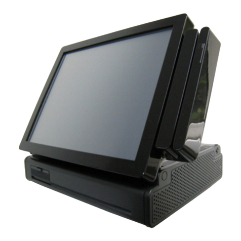
Longshine 15IW Series User manual

I
15IW Series
USER MANUAL
15” All-in-One True Flat Touch Screen POS System
Version: 1.0
Date: 06. May. 2022

II
Table of Contents
Table of Contents ....................................................................................................................................... II
1. Item Checklist .................................................................................................................................. 1
1-1 Standard Items ....................................................................................................................... 1
1-2 Optional Items ............................................................................................................................ 1
2. Identifying Components .................................................................................................................. 3
2-1 Front View Rear View ......................................................................................................... 3
2-2 Dimension ............................................................................................................................... 4
2-3 I/O View ................................................................................................................................... 5
3. System Assembly Disassembly .................................................................................................... 6
3-1 Replace the storage ............................................................................................................... 6
4. Peripherals Installation ..................................................................................................................... 7
4-1 Install the MSR/Multi-function module ............................................................................... 7
4-2 Install the Customer Display ................................................................................................. 8
4-3 Install the 2nd Display ......................................................................................................... 10
4-3-1 How to activate the 2nd display Under Windows ....................................................... 12
4-4 Install the Wall Mount Kit ................................................................................................... 15
5. Specification .................................................................................................................................. 17
6. Configuration .................................................................................................................................. 18
6-1 Motherboard Layout ............................................................................................................ 18
6-1-1 15IW Connectors Functions ............................................................................... 18
6-1-2 Connector Pin Definition ......................................................................................... 20
DC 12V Input Connector Pin Description ................................................................................... 20
SATA Connector Pin Description ................................................................................................. 21
C M Connector Pin Description ................................................................................................ 21
DC 12V utput Connector Pin Description ................................................................................ 21
VGA Connector Pin Description ................................................................................................. 22
LAN Connector Pin Description .................................................................................................. 22
USB 3.0 Connector Pin Description ............................................................................................ 23
Parallel Connector Pin Description ............................................................................................ 23
APPENDIX A:
Driver Installation ......................................................................................................... 24
A-1 Chipset Device Driver .......................................................................................................... 24
A-2 VGA Driver ............................................................................................................................. 26

III
A-3 TXE Driver .............................................................................................................................. 30
A-3-1 TXE patch Driver ............................................................................................................ 32
A-4 USB 3.0 Driver ...................................................................................................................... 34
A-5 LAN Driver ............................................................................................................................. 37
A-6 Audio Driver .......................................................................................................................... 39
A-7 DPTF Driver ........................................................................................................................... 40
APPENDIX B:
Copyright and Trademark ............................................................................................ 41
Copyright ........................................................................................................................................... 41
Trademark Recognition ................................................................................................................... 41
Disclaimer ......................................................................................................................................... 41
Regulatory Notices .......................................................................................................................... 41
警告 .................................................................................................................................................... 41
警告使用者 ........................................................................................................................................ 41
注意事項 ............................................................................................................................................ 41
WARNING .......................................................................................................................................... 41
Revision History ................................................................................................................................ 42
Warranty Limits ................................................................................................................................ 42
IMPORTANT SAFETY INSTRUCTIONS ............................................................................................. 42
CE MARK ........................................................................................................................................... 42
FCC Statement ................................................................................................................................. 42
LEGISLATION AND WEEE SYMBOL ................................................................................................. 43
CAUTION ON LITHIUM BATTERIES .................................................................................................. 43
Safety Information ........................................................................................................................... 43

1
1. Item Checklist
1-1
Standard Items
A. System B. Power adapter
C. Power Cord D. USER Manual / Driver CD

2
1-2 Optional Items
A.MSR B.
Multi-function module
C. 2nd Display with back mount bracket D. Customer Display with back mount bracket
. Wall Mount kit (Device side) F. Wall Mount kit (Wall side)

3
2. Identifying Components
2-1
Front View Rear View
Number
Description
1
Power
LED
2
Power Button
3
Speaker
4
Wall mount
5
MSR Cover
Touch
screen
7
Swing
arm
base
8
C
able
cover
9
I/O Cable Cover
10
N
eck
C
over

4
2-2
Dimension

5
2-3
I/O View
Number Description
A 2.5”storage door
B COM3~6
C Mic in
D USB x 2 (USB2.0)
E Line out
F RJ-45 LAN
G USB x 4 (USB3.0)
H COM1~2
I VGA
J HDMI
K DC 12V out
L DC 12V in

6
3. System Assembly Disassembly
3-1
Replace the storage
1. Remove the 2.5”storage cover
retaining the screw and pull the
drive out.
2. Remove the screws (x4) that fix the
2.5”storage drive as shown in the picture.

7
4. Peripherals Installation
4-1
Install the MSR/Multi-function module
MSR or Multi-function module is installed on the right side of the system. Please make sure
the unit is turned off before starting the installation.
1. Remove the dummy cover first.
2. Connect the MSR cable (x1) to the
connector on the system side.
3. Insert the MSR module in place
and fasten the screws (x2) on the
back to secure the module.

8
4-2
Install the Customer
Display
1. Remove the 4 screws from back cover first and remove the swing arm.
2. Fasten the screws (x4) to secure the customers display to the system,
plug the USB Cable Into the USB connector on the system board.

9
3. Fasten the screws (x4) to secure the swing arm to the back cover.

10
4-3
Install the 2nd Display
1. Remove the 4 screws from back cover first and remove the swing arm.
2. Fasten the screws (x4) to secure the 2
nd
display to the system, plug the display and
DC Cable Into the VGA connector and 12V DC-I connector on the system board.

11
3. Fasten the screws (x4) to secure the swing arm to the back cover.

12
4-3-1
How to activ
ate the 2nd display Under Windows
Make sure to connect the 2
nd
display cable and begin the installation after your
system has booted.
The Setup program requires about one minute for the installation. If you turn the
power off or remove the 2
nd
display cable while the Setup program is running, it
may cause an error with the Windows operating system.
The optimal resolution for this VGA monitor is 1024 x 7 8.
When the installation is completed, configure the following settings to activate the 2
nd
display.
1. Click the Start button Picture of the Start button in the lower-left corner of the screen.

13
2. Click the Control Panel to change the setting and customize the functionality of the
system.
3. Click the Appearance and Personalization to enter the menu.

14
4. Select Display from the menu and the display properties windows appears.
5. Arrange the monitors displayed in the order they are actually used.
6. Remember to click Apply before exiting the menu.

15
7. Click Keep Changes and then click OK to save the setting.
4-4
Install the Wall Mount Kit
The wall mount come with the following parts:
1. First attach the four mounting clips using the 4 mm screws as shown in the picture.
2. Next attach the mounting bracket to the wall or other surface using at
least four of the bracket mounting holes. Please note that the bracket has both
a 100mm hole pattern, so that the bracket can be used with the VESA bracket
as well as being directly mounted to a wall.

16
3. Next step is to route any cables you need to go to the system as required.
Cables can also be routed down as well. You can remove the system on and off
the wall mount bracket as needed to route the cables.

17
5. Specification
Table of contents
Other Longshine Touch Terminal manuals

Longshine
Longshine GFT-150 Series User manual

Longshine
Longshine RCT150 User manual

Longshine
Longshine COBRA15 User manual

Longshine
Longshine COBRA15 User manual

Longshine
Longshine POS GFT-150 Series User manual

Longshine
Longshine GFT-150 Series User manual

Longshine
Longshine RDT-150F Series User manual

Longshine
Longshine CRANE 1 User manual

Longshine
Longshine POS GT-150 Series User manual