MRC INC-150-CO2-O2 User manual

INC-150-CO2-O2
CO2 Incubator
Instruction Manual
3, Hagavish st. Israel 58817 Tel: 972 35595252, Fax: 972 3 5594529
MRC. 11.23

1
Technical Specification Tri-Gas Incubator
Copyright
No part of this specification, including pictures, audio and video products, shall be
reproduced or disseminated in the name of any individual or organization without
the consent ofMRC.
Equipment operators can copy some chapters of this specification, which are
clearly indicated in the contents and for internal use only, for example, teaching
users to handle emergency.

2
Responsibility and Obligations
Technical Specification for Tri-gas Incubator
MRC shall have no obligation and responsibility for any damage on the instrument
caused by users for failing to comply with the operation instruction and the
Environmental Requirements stated in this specification
MRC is entitled to modify the content of the specification at any time without
appropriate notification

3
Technical Specification for Tri-Gas Incubator
Environmental Requirements
Indoor use only, the equipment shall avoid direct exposure to the sun
Sufficient ventilation equipment shall be installed in the work place
℃The best working temperature shall be 18℃--30
The relative humidity of the working environment shall be no more than 80%
The incubator shall be placed on a flat, solid and fire-retardant platform which can
support its weight
There shall be no inflammable, explosive, corrosive, toxic or harmful gas that may
cause sharp temperature change in the vicinity of the equipment
Any large-power heat generating equipment and radiation source may give negative
impact on the normal operation of the incubator, so please don’t place them near the
incubator
There shall be no electromagnetic interference source nearby
MRConly commits that the incubator can operate normally in the place where the
elevation is under 2000m
The power supply voltage of this equipment shall be allowed to change within±10% of
the rated working voltage
The transient over-voltage of the power supply shall be class II
The pollution degree is Class II

4
Technical Specification for Tri-Gas Incubator
Safety Tips
.Please read this specification carefully before using this machine for the first time
.The incubator can be only operated by the trained and authorized person
.The maintenance can be only conducted by MRC or its authorized agency
,The maintenance spare parts shall be provided by the manufacturer and MRC
.and users are not allowed to replace them without authorization
It’s prohibited to use any materials that may cause combustion or explosion in the equipment, because
.the emitted steam or explosion debris may cause damage on the equipment
The intake pressure of CO2must maintain stable. Users can adjust the output pressure
. of reducing valve in the range of 0.08 to 0.1 Mpa
CO2is a kind of gas that may be harmful to the health of people. When agreat deal of
such gas is released in the room with the concentration exceeding acertain proportion, operators may
be suffocated. Therefore, the working environment must be equipped
with sound ventilation equipment, and there shall be corresponding safety protection measures for
.CO2storage vessel for fear of leakage
Only qualified maintenance personnel can operate the intake pipe of the incubator, compression
,vessels, cylinders or other systems that are used to store CO2
.with proper tools
The power supply of the incubator shall be well grounded so as to prevent operators from electric
. striking

5
Explaination of Warning Labels
Technical Specification for Tri-Gas Incubator
Note: Pease read this specification carefully before
using the instrument. al specification carefully before using the
instrument.
Note: high temperature, be cautious.
Broken glass!
Grounding protection!
Note: Main fuse

6
Technical Specification for Tri-Gas Incubator
Quick Guide to Operation of Tri-gas Incubator
Restore settings:
Temperature control value 37.0℃
Humidity alarm value 90%(not controlled)
CO2control value 0.0%
CO2supply circuit A circuit
The metal surface in the interior of the equipment (inner chamber, motor
impeller, fan cover, shelf, support and so on) shall be sprayed with H2O2before
use, and cleaned with soft cotton cloth so as to get rid of dirt and sundries.
As a required step to operate the incubator normally, this operation can’t be
omitted. Otherwise, it will directly affect incubation effect, or even lead to
failure. (Please refer to 8.1.6 Shortcut Menu—90℃high-temperature and
high-humidity disinfection for the specific operation method).
After disinfection, calibration and verification shall be conducted before
incubation in accordance with following steps.
1. Please turn off the power switch and cut off the power.
2. Open the external door and the glass doors, inject about 3L of distilled water
into the bottom of the inner tank of the incubator, and then close the doors.
3. Connect the gas source. Select one or two circuit of CO2supply according to
the actual operation requirements, adjust the output pressure of reducing
valve in the range of 0.08 to 0.1MPa, and check whether there is any gas
leakage. Please refer to the Installation and Operation Instruction of CO2
Reducing Valves for the specific operation method.
4. Connect the power supply. Connect AC power via power wire, turn on the
power switch in the lower right side of the control box at the back of the
incubator to start up the equipment after the connected power
supply meets the stipulated requirements.
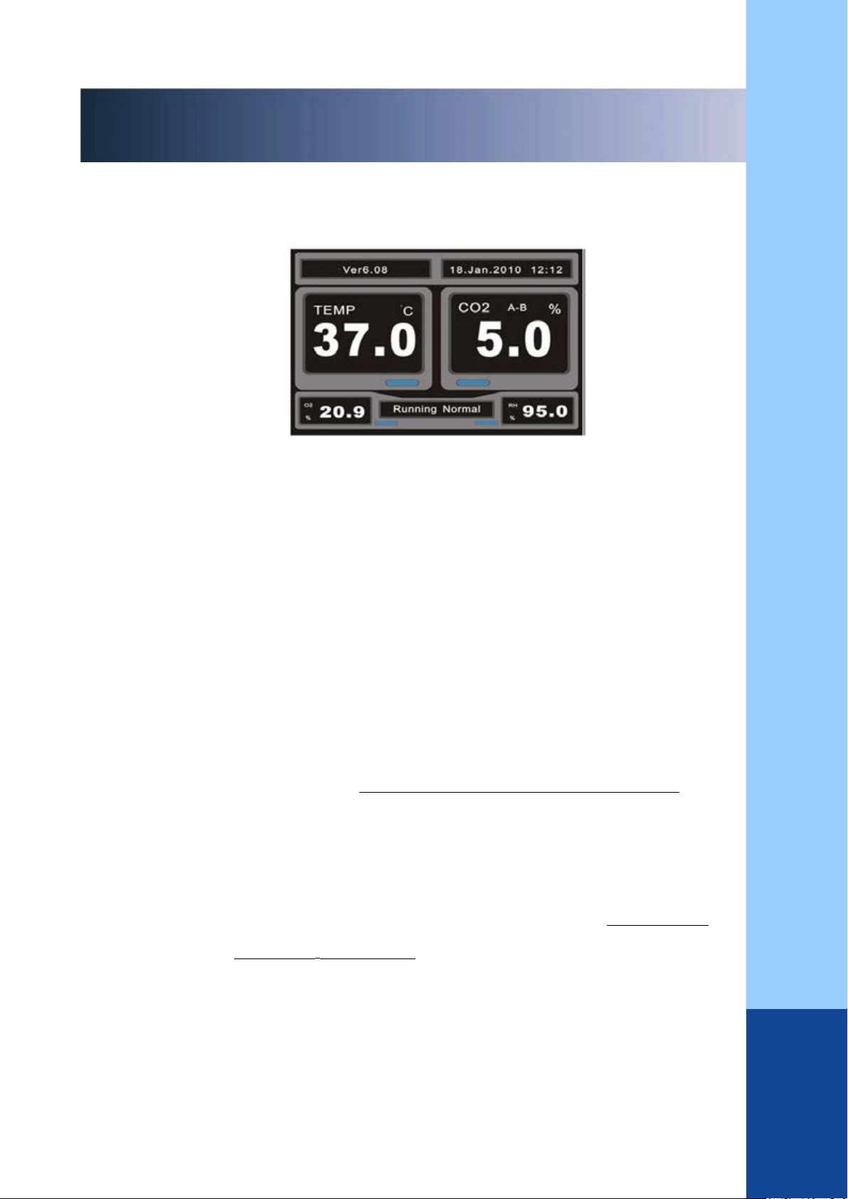
5.After the Logo of “MRC”is displayed in LCD, the system will start
self-testing for about 30 seconds, and the inspection process and result will
be synchronized in LCD.

7
Technical Specification for Tri-Gas Incubator
Quick Guide to Operatation of Tri-gas Incubator
6.After self-testing, LCD will display the main interface when the system is
under normal conditions.
Fig. 7.3.1 Display of Main Interface: Text Box Interface (system default)
7. After the equipment enters into the main interface, users can set the control
parameters via keys according to their own requirements, including,
temperature, CO2concentration, Room temperature, CO2supply circuit and
so on.
8. The system initializes the automatic zeroing of CO2sensor in order to ensure
the accuracy of CO2concentration.
As for equipment installed with TCD sensor, the procedure of TCD
AUTOSTART can be directly done in the start-up initial period.
(Please refer to 8.1.8 Shortcut Menu—TCD AUTO START for
specific operation).
As for equipment installed with IR sensor, IR Auto Zero can be
started after the temperature in the chamber reaches the setting value
and keeps stable for one hour (Please refer to 8.1.7 Shortcut
Menu—CO2IR Auto Zero for specific operation).
After initialization, the equipment can be put into use.
9. Afterwards, users can set parameters via shortcut.
After users confirm the setting of parameters, the incubator will automatically
intake air and control the temperature, CO2concentration until the control
parameters set by users are reached and stabilized, so the equipment can start
incubation.

8
Technical Specification for Tri-Gas Incubator
Quick Guide to Operatation of Tri-gas Incubator
Method of using shortcut keys:
Shortcut menu moves forward
Shortcut menu moves backward
It displays the switche between the shortcut menus of “temperature control”, “CO2control”
and so on in cycle, and users can reset the value of corresponding menu according to their
own requirements.
The value increases
The value decreases
Confirm
After confirmation, the incubator will start to control the temperature, CO2concentration
and according to the latest parameters set by users until the control value set by users are
reached and stabilized, so the incubator can start work.
10. At the end of incubation, the default value of the parameters must be
restored according to the above step in order to stop the incubator, and following three
steps shall be conducted, so users can continue to operate the equipment.
A. Drain the water of the water tank, please refer to 8.1.5 Shortcut Menu-Drainage for
specific methods.
B. After above operation, turn off the power switch, which is located in
the right bottom of the back of the incubator, and cut off the power.
C. Keep the glass doors fully opened for about 10 minutes so as to empty
the gas from the chamber, dry the surrounding and the bottom of the inner
tank with soft cotton cloth, and then close all doors of the incubator.

9
Technical Specification for Tri-Gas Incubator
Installation and Operation Instruction of CO2 Reducing Valves
Reducing valves shall match with the applied gas, and not mix, otherwise,
they will be damaged and the reading of intake pressure will be not accurate.
Before installation, it shall close the output switch of the reducing vale and
the main valve switch of steel cylinders, then install the valve in the steel
cylinder and screw down the nut of the interface with wrench to ensure no
leakage.
Open the main valve switch of steel cylinders after making sure that the
output switch of reducing valve is closed, and then adjust output pressure of
the valve in the range of 0.08 and 0.1MPa.
Recheck the gas supply circuit to make sure that there is no leakage in steel
cylinder, reducing valve, breathing line, interface and other links.
Before opening the gas supply valve of steel cylinder, first
close relevant reducing valves, then slowly open the gas
supply valve and reducing valves, adjust the outlet pressure
of the gas supply valve to 0.1MPa. The sequence of above
operation shall not reverse, otherwise, the intake pipe, filter
or pressure sensor will be damaged.

10
Technical Specification for Tri-Gas Incubator
Contents
Copyright......................................................................................................................................... .1
Obligations and Responsibilities...................................................................................................... 2
Environmental Requirements........................................................................................................... 3
Safety Tips........................................................................................................................................ 4
Explaination of Warning Labels....................................................................................................... 5
Quick Guide to Operation ofCCTri-gas Incubator................................................ 6
Installation and Operation Instruction of CO2................................................................................. 9
Contents.......................................................................................................................................... 10
I. Brief Introduction........................................................................................................................ 13
1.1 Front view of the opened incubator..................................................................................14
1.2Control Panel ofCCIncubator................................................................. 15
1.2.1 Operation instructionof nagivation key.................................................................16
Display interface ofCCincubator................................................................. 17
Text box interface ofCCincubator....................................................... 17
1.3.2Curve interface ofCCincubator.....................................................18
1.3.3 Switch beween the two display interfaces............................................................ 19
1.4Back view ofCCincubator....................................................................... 20
1.5 Side view of the electric control box................................................................................22
II. Mechanical Structure............................................................................................................. 23
2.1 Shell and inner tank.......................................................................................................... 23
2.2 Accessories of inner tank..................................................................................................23
2.3 Three small glass doors.................................................................................................... 24
2.4 Drainage equipment..........................................................................................................24
2.5 O2and N2humidifying equipment (Not applicable)................................................... 25
2.6 Pressure compensated orifice and guide plate.............................................................. 25
2.7 Wire incoming and air inlet hole for testing equipment.............................................. 26
2.8 Gas concentration sampling hole...................................................................................26
III. Electric Structure...................................................................................................................... 27
3.1 Heating system................................................................................................................ 27
3.2 Humidity.......................................................................................................................... 27
3.3 Serial communication interface..................................................................................... 28
3.4 Remote alarm interface...................................................................................................28
3.5 Power switch and power socket..................................................................................29
IV. Structure of Gas Circuit.......................................................................................................... 30
4.1 CO2intake system........................................................................................................... 30

11
Technical Specification for Tri-Gas Incubator
Contents
4.2 O2or N2intake system (Not applicable).................................................................................31
V. Sensor system...................................................................................................................................... 32
5.1 Sensor base................................................................................................................................ 32
5.2.....................................................................................................................................................33
5.3 Water level sensor.................................................................................................................... 33
5.4 Ambient temperature sensor..................................................................................................344
VI.Installation of the Incubator.......................................................................................................... 345
6.1 Environmental requirements................................................................................................. 345
6.2 Instruction on indoor ventilation...........................................................................................345
6.3 Requirements for installation space......................................................................................345
6.4 Requirements for handling.................................................................................................... 346
6.5 Stacking method.......................................................................................................................37
6.6 Door opening direction............................................................................................................ 37
VII. VII. Initialization of System Startup................................................................................................38
MRCLOGO...................................................................................................................38
7.2 System self-testing................................................................................................................... 38
7.3 System main interface.......................................................................................................39
VIII. System Menu and Parameter Setting..............................................................................................40
8.1 Access to the shortcut menu and switch between sub-menus.............................................. 40
8.1.1 Shortcut menu-Temperature control................................................................................. 40
8.1.2 Shortcut menu-CO2control.............................................................................................. 41
8.1.3 Shortcut menu—.............................................................................................................. 42
8.1.4 Shortcut menu-CO2gas guard set..................................................................................... 42
8.1.5 Shortcut menu— Drainage............................................................................................... 43
8.1.6 Shortcut menu— Disinfection.......................................................................................... 44
8.1.7 Shortcut menu—CO2IR Auto Zero................................................................................. 45
8.1.8 Shortcut Menu—TCD AUTO START.............................................................................. 46
8.2 Access to the main menu and switch between sub-menus................................................... 48
8.2.1 CONTROL SET............................................................................................................. 49
8.2.1.1 CONTROL SET—TEMP Value...................................................................... 50
8.2.1.2 CONTROL SET—CO2Value.......................................................................... 52
8.2.1.3 CONTROL SET—RH Alarm Value)............................................................... 54
8.2.1.4 CONTROL SET—Gas Guard Set.......................................................................54
8.2.1.5 CONTROL SET—.............................................................................................. 55
8.2.2 CALIBRATION............................................................................................................. 57
8.2.3 FUNCTION(Adjustment and starting of system function)................................... 59
8.2.3.1 Disinfection Start.................................................................................................59

12
Contents
Technical Specification for Tri-Gas Incubator
8.2.3.2 Draning start................................................................................................. 60
8.2.3.3 Fan state........................................................................................................ 60
8.2.3.4 IR AUTOZERO.........................................................................................61
8.2.3.5 IR CO2 Manual Zero).............................................................................61
8.2.3.6 TCD AUTOSTART................................................................................... 62
8.2.3.7 TCD CO2 Manual Zero................................................................................62
8.2.4 SYSTEM SET......................................................................................................... 63
8.2.4.1 Data and Time Set........................................................................................ 63
8.2.4.2 Run Model Set.............................................................................................. 64
8.2.4.3 Alarm Buzz EN Set...................................................................................... 65
8.2.4.4 Curve XY Set.................................................................................................65
8.2.5 INFORMATION......................................................................................................66
8.2.5.1 Alarm information........................................................................................ 66
8.2.5.2 System Information................................................................................... 67
8.2.5.3 Sensor AD Data............................................................................................ 68
8.2.5.4 History Data..................................................................................................68
8.2.5.5 Temp Sensor Data).....................................................................................69
8.2.6 SYSTEM HELP...................................................................................................... 69
8.2.6.1 Key introduce............................................................................................... 70
8.2.6.2 Factory SN Check......................................................................................70
8.2.6.3 Access Data Set............................................................................................ 71
8.2.6.4 Ver. Check.....................................................................................................71
IX. Product Technical Parameters.................................................................................................... 72
9.1 Product overview................................................................................................................ 72
9.2 Basic parameters of the incubator...................................................................................... 73
9.3 Model and configuration.................................................................................................... 74
X. System Information and Fault Treatment.................................................................................... 79
10.1 Fault information and elimination instruction..................................................................79
10.2 English-Chinese alarm iformation list..............................................................................80
10.3 Fault information and elimination instruction..................................................................81
XI. CC Serial Communication Protocols..................................................................84
Conclusion........................................................................................................................................ 85

13
Technical Specification for Tri-Gas Incubator
I. Brief Introduction
CC tri-gas incubator is asophisticated laboratory instrument, which can simulate
the natural physiological environment of cells and tissues. It is mainly applied in medical
treatment and biological experiment for incubation of biological cells, tissues and bacteria,
microcomputer is accurately adopted to control the temperature and concentration of CO2,
meanwhile, thanks to the function of 90℃high-temperature and high-humidity disinfection, the
success rate of incubation has increased greatly, consequently, it’s an important scientific
instrument for you to conduct high-level biological and medical experiment
Please carefully read this specification before using the instrument, so you can handle it without
any difficulty, greatly improve your working efficiency and reduce unnecessary damage on the
instrument.
In order to improve our service quality and level, MRC kindly reminds you of the following
aspects
Only the test and maintenance conducted by the professional technical engineer of our
company according to the requirements can comply with corresponding safety standards
and ensure the normal operation of the incubator.
Besides, only the trained or professional technicians can operate this instrument.
Please indicate the serial number of your instrument when submitting a fault report or
purchasing spare parts.
The incubator require a stable working platform without the existence of inflammable,
explosive, corrosive, toxic and harmful gas that may cause sharp temperature change in
its vicinity. Such environment is in favor of normal operation and incubation, otherwise,
it will directly affect abnormity and failure of incubation.
The important parts of the specification are marked with .

14
Technical Specification for Tri-Gas Incubator
I. Brief Introduction
1.1 The front view of the opened incubator
Fig. 1.1 Front View of Opened CC Incubator
No. Name of the part No. Name of the part
1
Top foot
(
Stack foot
)
13
Water outlet
2
Door switch
14
3Sensor base 15 Supporting bar
4Incoming wire and air inlet 16 Handler of small glass door
5Holder of glass door 17 Magnetic door sealer
6Support frame 18 Handler of large glass door
7Inner tank 19 External glass steel door
8
Silicone door sealer
20
Small glass door
9
Bottom foot
21
Large glass door
10 Adjusting screw 22 Pressure compensated orifice
11 Shelf 23 L-type door hange
12 Water inlet 24

15
Technical Specification for Tri-Gas Incubator
I. Brief Introduction
1.Control panel of CC incubator
Fig.1.2 Control Panel of CC Incubator
No.
Name of
the part Function description
1ESC key
Press this key to return to the superior menu during
switching among function menus, and to cancel the
operation in data modification.
2ENTER
key
Press this key to enter into the menu during switching
among function menus, to confirm data modification after
saving the setting, and to enter into the main display menu
of the text box.
3LCD
It’s a 5.7-inch TFT color LCD, displaying all current
running parameters and the state of the system.
There are two display interfaces, namely, text box
and curve
4Navigation
key
Please refer to 1.2.1 Operation Instruction of
Navigation Key for specific operation methods.

16
Technical Specification for Tri-Gas Incubator
一I. Brief Introduction
1.2.1 Operation instruction of navigation keys
When the current interface is the main interface
Press and to switch between the two main display interfaces
(text box and curve).
Press and to switch among the setting menue of shortcut parameters.
When the current interface is the main interface
Press this key once, the menu item will move one step forward.
Press this key once, the menu item will move one step backward.
Press this key once, the menu item will move one step in the left.
Press this key once, the menu item will move one step in the right.
When the current state is for data modification:
Press this key once, the data value will increase by 1.
Press this key once, the data value will decrease by 1.

17
Technical Specification for Tri-Gas Incubator
I. Brief Introduction
1.3Display interface ofCCincubator
1.3.1Text box interface ofCCincubator
Fig.1.3.1 Display of Text Box Interface
No.
Display content
Remark
1Product model and software
copyright
2
Calendar and clock
3Current gas supply circuit of CO2
steel cylinder
There are four gas supply modes, A circuit, B
circuit, automatic switch from A to B circuit,
and automatic switch from B to A circuit,
which can be set in the main menu or shortcut
menu.
When gas supply is normal, the letter will be
in blue, and when there is no gas in the circuit,
the letter will be in red.
4Current actual CO2concentration
in the chamber
5Indication of CO2control state
When it is red and flashes, it indicates intake or
control state, and when it becomes dull and
motionless, it means that CO2is not controlled.
6Current actual relative humidity in
the chamber
When the data is in red, it means that the water
level of the tank is under the minimum limit, and
distilled water is required.

18
Technical Specification for Tri-Gas Incubator
一、I. Brief Introduction
1.3.2Curve interface of incubator
Fig.1.3.2 Display of Curve Interface
No. Display content Remark
7Running state or alarm
information
When the incubator runs normally, “Running
Normal” will be displayed. When the system gives
an alarm, relevant alarm information will be
displayed, and when there are multiple pieces of
alarm information existing, the information will be
displayed in cycle. As for details, please refer to 10.2
English-Chinese alarm iformation list.
8
9Ambient temperature The current ambient temperature surrounded the
equipment (for instance, ET 25.0℃).
10 Indication of temperature
heating state
When it is in red and flashes, it means heating
driving control state, and when it becomes dull and
motionless, it means that the heating control stops.
11 Current actual temperature in the
chamber

19
Technical Specification for Tri-Gas Incubator
I. Brief Introduction
Note: As displayed in Fig. 1.3.2, when the door is opened, the temperature, CO2concentration, O2
concentration and relative humidity will dropp at the same time. After the door is closed, they will
gradually go up to the setting value and become stablizied.
1.3.3 Switch beween two display interfaces
When the intialization is completed, the default display interface is text box, but users can
switch between these two display interfaces (text box and curve) by pressing these two
keys.
No.
Display content
Remark
1Door opened/closed state
Displayed by DOOR and grey line.
The “low level” in the picture indicates the
state of door open, and the “high level”
indicates the state of door close. From X axis,
we can know the time when the door is opened
or closed.
2Curve of current temperature
and time
The corresponding red curve indicates the
change trend of temperature.
3Curve of current CO2
concentration and time
The corresponding yellow curve indicates the
change trend of CO2concentration.
4Curve of current relative
humidity and time
The corresponding blue curve indicates the
change trend of relative humidity.
5
6Calendar and clock The calendar is displayed in green, and the
green horizontal axis indicates the time.
Table of contents
Other MRC Laboratory Equipment manuals
Popular Laboratory Equipment manuals by other brands

logos biosystems
logos biosystems CELENA X user manual

Evertree
Evertree Liva EBS Series user manual

EMP-Centauri
EMP-Centauri P.123-A instruction manual

ThermoFisher Scientific
ThermoFisher Scientific invitrogen iSort Series manual

Agilent Technologies
Agilent Technologies 7200 Operation manual

caron
caron 2050 Operation manual