LOVATO ELECTRIC BCG0612 User manual

I372 GB I 10 14 31100184
1
LOVATO ELECTRIC S.P.A.
24020 GORLE (BERGAMO) ITALIA
VIA DON E. MAZZA, 12
TEL. 035 4282111
FAX (Nazionale): 035 4282200
FAX (International): +39 035 4282400
E-mail info@LovatoElectric.com
Web www.LovatoElectric.com
BCG0612 - BCG0524
BCG1212 - BCG1024
WARNING!
– Carefully read the manual before the installation or use.
– This equipment is to be installed by qualified personnel, complying to current standards, to avoid
damages or safety hazards.
– Disconnect the power supply before any connection or disconnection is done through the charger
terminal block.
– The manufacturer cannot be held responsible for electrical safety in case of improper use of the
equipment.
– Products illustrated herein are subject to alteration and changes without prior notice. The technical
data and description in this documentation are subject to alterations and changes at any time and
have no contractual value.
– A circuit breaker easy accessible must be included outside of the device.
– The device is exclusively intended for installation in areas accessible only to service personnel as
defined by chapter 1.2.13.5 of IEC/EN 60950-1.
– Clean the instrument with a soft dry cloth; do not use abrasives, liquid detergents or solvents.
IMPORTANT
– Do not use the battery charger in proximity of explosive gases and/or other inflammable material.
– Arrange for adequate air flow of the battery room during recharging.
– Should the battery charger be disconnected from the power supply for a long period of time, it is
recommended to disconnect the batteries from the battery charger. Connection for long periods of
inactivity may discharge the batteries.
INTRODUCTION
The "BCG" device is a battery charger working with constant voltage and constant current charge cycle
suitable for lead-acid batteries. Different versions are available: BCG 0612 (12V – 6A), BCG0524 (24V –
5A), BCG 01212 (12V – 12A) and BCG1024 (24V – 10A). The maximum current is then adjustable in a
range between 20% and 100% of full scale. The charging voltage is selectable between two levels and a
boost voltage can be applied as well.
The protection trips are indicated by LEDs and output contact.
The switching technology which BCGs are based on lets high efficiency and at the same time a wide
range of power supply.
Based, din rail or vertical mounting with the appropriate accessory (only BCG0612 and BCG0524
versions) can be choosen.
DESCRIPTION
– Switching technology
– Reduced weight and dimensions
– Wide range power supply (110…240VAC)
– High efficiency
– “Constant current” – “Constant voltage” charging cycle (DIN41773)
– 2 charging voltage levels selectable through dip switches (2.25V and 2.3V per battery element)
– Trimmable charging current (from 20% to 100% of rated value)
– External BOOST command to deeply charge the battery
– “Hiccup” function to charge the battery in case of battery voltage level lower than 50% of rated one
– “Low battery voltage”, “short circuit” and “reverse battery” alarms.
– 4 signalling LEDs
– 1 relay output to remote the battery status (with changeover contact)
– Operating temperature -30…+55°C (70°C with derating)
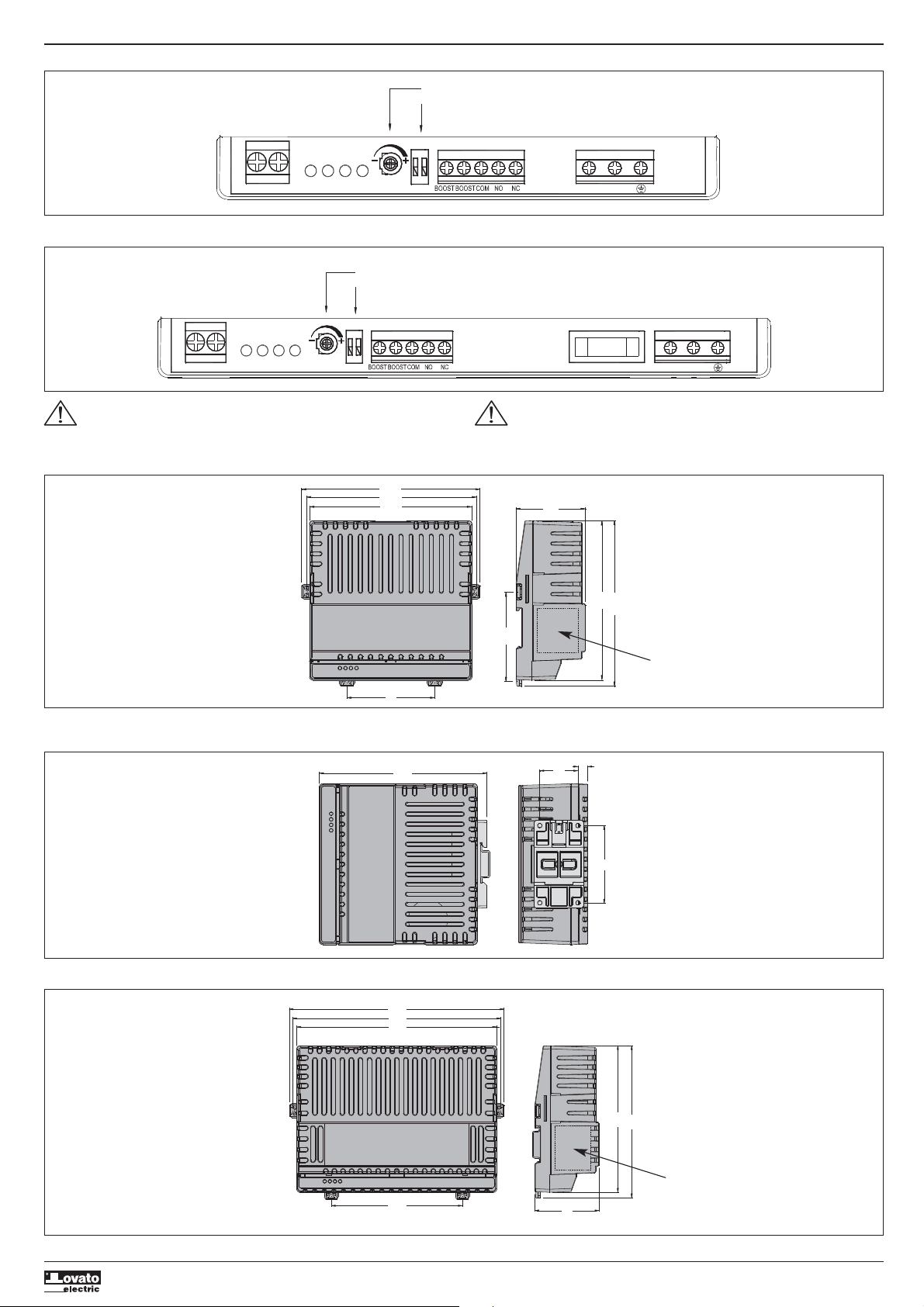
SIGNALLING DESCRIPTION
LED "ON" (Power ON) indicates that the battery charge is power supplied.
LED "CHG" (CHARGE) means the charging current is higher than 30% of the set one.
LED "ALA” (ALARM) warns about an alarm condition.
LED “REV” (REVERSE) indicates that the battery connection is inverted.
ALARM RELAY
The battery charger is equipped with a normally powered changeover relay output. In case of alarms
(“ALARM” or “REVERSE” LED on) the relay output is not powered.
CONNECTIONS
Keep the distance between the battery charger and the battery as short as possible; consider the use of
cables of the right size to avoid voltage drops which can cause an incorrect battery charging.
Connect all those devices which need the battery voltage directly to the battery poles and not to the
battery charger terminals.
Connect the battery poles to the device battery terminals before powering on the battery charger and
control the battery connection through REV LED it must be off.
Install a fuse at the battery charger output terminals (See technical characteristics).
ATTENZIONE!!
– Leggere attentamente il manuale prima dell’utilizzo e l’installazione.
– Questi apparecchi devono essere installati da personale qualificato, nel rispetto delle vigenti normative
impiantistiche, allo scopo di evitare danni a persone o cose.
– Sconnettere la rete di alimentazione prima di qualsiasi connessione o sconnessione sulla mersettiera
del carica batterie
– Il costruttore non si assume responsabilità in merito alla sicurezza elettrica in caso di utilizzo
improprio del dispositivo.
– Le descrizioni ed i dati contenuti in questo manuale sono suscettibili in qualsiasi momento di
evoluzioni o di modifiche, e non possono pertanto avere nessun valore contrattuale
– Un dispositivo di sezionamento facilmente accessibile deve essere incorporato all’esterno
dell’apparecchiatura.
– L’apparecchio è destinato esclusivamente all’installazione in aree accessibili al solo personale di
servizio come definito dal §1.2.13.5 della IEC/EN 60950-1.
– Pulire l’apparecchio con panno morbido, non usare prodotti abrasivi, detergenti liquidi o solventi.
IMPORTANTE
– Non utilizzare il carica batterie vicino a gas esplosivi o altro materiale infiammabile.
– Provvedere ad un’adeguata ventilazione del locale batterie durante la ricarica.
– Nel caso il carica batterie rimanga disalimentato per un lungo periodo si consiglia di scollegare le
batterie dal carica batterie. Mantenere il collegamento per lunghi periodi di inattività può provocare la
scarica delle batterie.
INTRODUZIONE
L’apparecchio "BCG" è un carica batterie a tensione e corrente costante per la carica in tampone di
batterie al piombo. Sono disponibili le versioni BCG 0612 (12V – 6A), BCG0524 (24V – 5A), BCG 01212
(12V – 12A) e BCG1024 (24V – 10A). La corrente massima è poi regolabile in un range compreso tra il
20% e 100% del fondo scala. La tensione di carica è invece selezionabile tra due livelli e su questi è
possibile applicare anche una tensione di boost.
Gli interventi delle protezioni presenti sono indicati tramite led e contatto di uscita.
La tecnologia switching con cui sono realizzati permette alta efficienza e nel contempo un ampio range di
alimentazione.
I “BCG” possono essere montati a fondo quadro, su guida din oppure a libro mediante l’apposito
accessorio ( solo versioni BCG 0612 e BCG0524).
DESCRIZIONE
– Tecnologia switching
– Dimensioni e peso contenuto
– Tensione di alimentazione a range esteso (110…240VAC)
– Alta efficienza
– Ciclo di carica “corrente costante” – “tensione costante” (DIN41773)
– 2 tensioni di carica impostabili da dip switch (2,25V e 2,3V elemento)
– Corrente di carica regolabile dal 20% al 100%
– Comando esterno di BOOST per carica a fondo della batteria
– Funzione “Hicc-up” per ricarica in presenza di batteria con tensione inferiore al 50% della nominale
– Allarmi di “Bassa tensione batteria”, “Corto circuito” e “Batteria invertita”.
– 4 LED di segnalazione
– 1 uscita a relè per remotazione stato carica batterie (con contatto in scambio)
– Temperatura di esercizio -30…+55°C (70°C con derating)
DESCRIZIONE DELLE SEGNALAZIONI
LED "ON" (Power ON) indica che l’apparecchio è alimentato.
LED "CHG" (CHARGE) indica che la corrente di carica è superiore al 30% di quella impostata.
LED "ALA” (ALARM) indica una condizione di allarme.
LED “REV” (REVERSE) indica che la batteria è connessa con polarità invertita.
RELÈ ALLARME
Il carica batterie dispone di una uscita di allarme a relè normalmente eccitato. Al verificarsi di una
condizione di allarme (LED “ALARM” o “REVERSE” acceso) o in mancanza della tensione di rete il relè si
diseccita.
COLLEGAMENTO
È buona norma posizionare il carica batteria il più vicino possibile alla batteria ed utilizzare cavi di
connessione di sezione adeguata; diversamente le cadute di tensione sui cavi non consentono una
corretta carica della batteria.
I dispositivi da alimentare devono essere connessi direttamente sui poli della batteria e non sui morsetti
del carica batterie.
Connettere la batteria prima di alimentare il dispositivo e verificare la corretta polarità mediante il LED REV.
Prevedere un fusibile in uscita al caricabatterie (vedi Caratteristiche Tecniche).
AUTOMATIC BATTERY CHARGER
Instruction manual
GB
CARICA BATTERIE AUTOMATICO
Manuale operativo
I

I372 GB I 10 14 31100184
2
MOUNTING
Install the battery charger according to one of the positions indicated in the instructions manual.
For vertical mounting it is necessary to add the optional accessory BCG X00.
The environment must be clean, with neither conductive powder nor water.
Keep enough space around the battery charger to let a correct air flow for cooling the device (see details
below).
Plastic enclosures are not recommended because of the bad heat conduction characteristics.
Good air flow inside the enclosure or panel is necessary.
MONTAGGIO
Installare il carica batterie nelle posizioni indicate nel manuale.
Per il montaggio in posizione verticale è necessario l’accessorio opzionale BCGX00.
Assicurarsi che l’ambiente sia pulito, privo di polvere elettricamente conduttiva e privo di acqua.
Lasciare spazio sufficiente attorno al caricabatteria per consentire la libera circolazione dell’aria
indispensabile al raffreddamento (vedi figura sotto).
Sono sconsigliate cassette in materiale plastico in quanto cattive conduttrici di calore.
Garantire una buona circolazione dell’aria all’interno della cassetta o armadio.
30mm 30mm
30mm 30mm
20mm 20mm
20mm 20mm
WIRING DIAGRAMS
SUPPLY
BATTERY
VOLTAGE AND CURRENT
CHARGING CONTROL
FUSE
OUT ALARMBOOST
110-240VAC
COM NO NC LN
FUSE
LOAD
BCG 0612 - 8A T
BCG 0524 - 6.3A T
BCG 1212 - 16A T
BCG 1024 - 12.5A T
SCHEMI DI COLLEGAMENTO
CHARGING DIAGRAM (DIN 41773)
U
Uc
0.5Uc
Ic
I
b
a
CURVA DI CARICA (DIN 41773)
Alarms ON REV ALA CHG RELAY
GRN RED RED YEL
LED LED LED RED
Correct output voltage ON OFF OFF OFF Energised
Charging ON OFF OFF ONEnergised
Low battery voltage ON OFF ON ONEnergised
Reverse polarity OFF ON OFF OFF De-energised
Short circuit / Overload ON OFF ON OFF De-energised
Steady light if the charging current is more than approx. 30% of programmed current value.
Flashing during Hiccup operating conditions.
Allarmi LED LED LED LED RELÈ
ON REV ALA CHG
VERDE ROSSO ROSSO GIALLO
Tensione di uscita corretta ON OFF OFF OFF Eccitato
In carica ON OFF OFF ONEccitato
Bassa tensione batteria ON OFF ON ON
Disec
citato
Inversione polarità OFF ON OFF OFF
Disec
citato
Cortocircuito e sovraccarico ON OFF ON OFF
Disec
citato
Acceso fisso se la corrente di carica è superiore a circa al 30% della corrente impostata.
Lampeggio in presenza di condizione di hiccup.

I372 GB I 10 14 31100184
3
BCG0612 - BCG0524 TERMINAL ARRANGEMENT DISPOSIZIONE MORSETTI BCG0612 - BCG0524
V2
LIMIT
CURRENT
20 -100% V1
ONCHGALAREV
LN
-
+-
SUPPLYBATTERY
RED
RED
YELLOW
GREEN
STATUS LEDs
BOOST AND RELAY
SPECIAL VOLTAGE SET
CURRENT ADJUST
BCG1212 - BCG1024 TERMINAL ARRANGEMENT DISPOSIZIONE MORSETTI BCG01212 - BCG1024
V2
LIMIT
CURRENT
20 -100% V1
ONCHGALAREV
LN
-
+-
SUPPLYBATTERY
RED
RED
YELLOW
GREEN
STATUS LED
BOOST AND RELAY
SPECIAL VOLTAGE SET
CURRENT ADJUST
LINE FUSE
ATTENTION:
Mount the terminal cover after connection.
ATTENZIONE:
Riposizionare il coperchio coprimorsetti dopo il collegamento.
BCG0612 - BCG0524 MECHANICAL DIMENSIONS [mm]
Standard (horizontal) mounting
162
159
149
80
63.2
81.5
145
150.5
DIMENSIONI MECCANICHE [mm] BCG0612 - BCG0524
Montaggio standard (sviluppo orizzontale)
Electrical data label position
Posizione etichetta dati elettrici
BCG0612 - BCG0524 MECHANICAL DIMENSIONS [mm]
Mounting with accessory BCG X00 (sideways)
136 35 9
71
DIMENSIONI MECCANICHE [mm] BCG0612 - BCG0524
Montaggio con accessorio BCG X00 (sviluppo verticale)
BCG1212 - BCG1024 MECHANICAL DIMENSIONS [mm]
213
206
198
130 63
145
151
DIMENSIONI MECCANICHE [mm] BCG1212 - BCG1024
Electrical data label position
Posizione etichetta dati elettrici

I372 GB I 10 14 31100184
GB
TECHNICAL CHARACTERISTICS
Supply
Model BCG0612 BCG0524 BCG1212 BCG1024
Rated voltage Us 110 - 240V
Operating voltage range 100 - 264V
Frequency 45 - 66Hz
Maximum current consumption at rated voltage 240V
/
0.96A 110V
/
1.54A 240V
/
1.52A 110V
/
2.62A 240V
/
1.6A 110V
/
3.1A 240V
/
2.7A 110V
/
5.1A
Maximum power consumption at rated voltage 240V
110V
240V
110V
240V
110V
240V
110V
230VA/95W 170VA/97W 364VA/154W 288VA/158W 384VA/184W 341VA/190W 630VA/298W 552VA/311W
Maximum power dissipation at rated voltage 240V
/12.4W 110V
/14.3W 240V
/15.9W 110V
/19.9W 240V
/23W 110V
/29W 240V
/28W 110V
/41W
Internal fuse T4A (time delay) not replaceable T6.3A (time delay) not replaceable T6.3A (time delay) 5x20mm T8A (time delay) 5x20mm
Battery charger circuit
Model BCG0612 BCG0524 BCG1212 BCG1024
Battery voltage 12V= 24V= 12V= 24V=
Type of battery Lead-acid battery (sealed and non sealed)
Charging cycle Constant voltage / constant current DIN 41773
Rated charging voltage Uc DIP 2 in V1 position 13.8V= (2.3V/cell) 27.6V= (2.3V/cell) 13.8V= (2.3V/cell) 27.6V= (2.3V/cell)
DIP 2 in V2 position 13.5V= (2.25V/cell) 27.0V= (2.25V/cell) 13.5V= (2.25V/cell) 27.0V= (2.25V/cell)
Boost charging voltage +4.4%
Max charging current 6A 5A 12A 10A
Efficiency at maximum rated voltage and maximum power ≥86.9% ≥89.7% ≥87.2% ≥90.2%
Charging current adjustment 20…100% Ic
Protections Overload with current limit / Battery polarity inverted / Output shortcircuit
External fuse T8A (time delay) T6.3A (time delay) T16A (time delay) T12.5A (time delay)
Output voltage variation related to supply (line regulation) <1%
Output voltage variation related to temperature <1%
Output voltage variation related to load (load regulation) <1%
Ripple and noise <1%
Signalling
1 green LED ON Power ON
1 yellow LED CHG Current charge ≥30% Ic
1 red LED ALA Overload and short circuit
1 red LED REV Battery reverse polarity
Output alarm circuit
Type of output Relay
Relay status Normally energised during operation. De-energised in alarm and power off. Automatic reset at the end of alarm.
Type of contact 1 changeover contact
Rated capacity 30V= 5A - 30V= 1A Pilot Duty
Electrical life / mechanical life 104 ops / 30x10
4
ops
Insulation
Rated insulation voltage Ui 250V
Protection class Class II / SELV
Double insulation between the voltage groups Power supply / Battery - Power supply / Enclosure - Power supply / Alarm relay
Power frequency withstand voltage 5kV
Ambient conditions
Operating temperature -30…+55°C without derating / -30…+70°C with current derating -1.5%Ic / °C.
+Derating with manual adjustment of the current limiting trimmer
Storage temperature -30…+80°C
Relative humidity <80% (IEC/EN 60068-2-78)
Maximum pollution degree 2
Overvoltage category 2
Climatic sequence Z/ABDM (IEC/EN 60068-2-61)
Shock resistance 15g (IEC/EN 60068-2-27)
Vibration resistance 0.7g (IEC/EN 60068-2-6)
Battery connections
Type of terminal Screw ( fixed)
Conductor cross section (min… max) 0.2 – 6 mm
2
UL Rating - Conductor cross section (min… max) 30 - 10 AWG
Tightening torque 0.5 Nm (5 lbin)
Supply connections
Type of terminal Screw ( fixed)
Conductor cross section (min… max) 0.2 – 2.5 mm
2
UL Rating - Conductor cross section (min… max) 30 - 12 AWG
Tightening torque 0.5 Nm (4 lbin)
Relay and Boost connections
Type of terminal Screw ( fixed)
Conductor cross section (min… max) 0.2 – 2.5 mm
2
UL Rating - Conductor cross section (min… max) 30 - 12 AWG
Tightening torque 0.5 Nm (4 lbin)
Housing
Version Base mount / Internal panel
Material Polycarbonate
Mounting On 35mm DIN rail (IEC/EN60715). By screw using extractable clips On 35mm DIN rail (IEC/EN60715)
Sideways (with optional accessory BCG X00) By screw using extractable clips
Degree of protection front IP20
Weight 530g 710g
Certifications and compliance
Certifications obtained cURus
Reference standards IEC/EN 60950-1, IEC/EN 61558-2-16 IEC 61000-3-2, IEC/EN 61000-6-2, IEC/ EN 61000-6-3, UL 60950-1, CSA C22.2 n° 60950-1
4

I372 GB I 10 14 31100184
5
I
CARATTERISTICHE TECNICHE
Alimentazione
Modelli BCG0612 BCG0524 BCG1212 BCG1024
Tensione nominale Us 110 - 240V
Limiti di funzionamento 100 - 264V
Frequenza 45 - 66Hz
Corrente massima assorbita alla tensione nominale 240V
/
0,96A 110V
/
1,54A 240V
/
1,52A 110V
/
2,62A 240V
/
1,6A 110V
/
3,1A 240V
/
2,7A 110V
/
5,1A
Potenza massima assorbita alla tensione nominale 240V
110V
240V
110V
240V
110V
240V
110V
230VA/95W 170VA/97W 364VA/154W 288VA/158W 384VA/184W 341VA/190W 630VA/298W 552VA/311W
Potenza massima dissipata alla tensione nominale 240V
/12,4W 110V
/14,3W 240V
/15,9W 110V
/19,9W 240V
/23W 110V
/29W 240V
/28W 110V
/41W
Fusibile interno T4A (time delay) not replaceable T6,3A (time delay) not replaceable T6,3A (time delay) 5x20mm T8A (time delay) 5x20mm
Circuito di carica batteria
Modelli BCG0612 BCG0524 BCG1212 BCG1024
Tensione della batteria 12V= 24V= 12V= 24V=
Tipo di batteria Pb (sigillato e non)
Ciclo di carica Corrente costante / tensione costante DIN 41773
Tensione nominale di carica batteria Uc DIP2 in posizione V1 13,8V= (2,3V elemento) 27,6V= (2,3V elemento) 13,8V= (2,3V elemento) 27,6V= (2,3V elemento)
DIP2 in posizione V2 13,5V= (2,25V elemento) 27,0V= (2,25V elemento) 13,5V= (2,25V elemento) 27,0V= (2,25V elemento)
Tensione di carica boost +4,4%
Corrente massima di carica Ic 6A 5A 12A 10A
Rendimento alla tensione nominale massima e alla potenza massima ≥86,9% ≥89,7% ≥87,2% ≥90,2%
Regolazione della corrente di carica 20…100% Ic
Protezioni Sovraccarico con limitazione di corrente / Inversione polarità batteria / Cortocircuito in uscita
Fusibile esterno T8A (ritardato) T6,3A (ritardato) T16A (ritardato) T12,5A (ritardato)
Variazione della tensione d’uscita in rapporto alla tensione di aliment. (regolazione di linea)
<1%
Variazione della tensione d’uscita in rapporto alla temperatura <1%
Variazione della tensione d’uscita in rapporto al carico (regolazione di carico) <1%
Ripple and noise <1%
Segnalazioni
1 LED verde ON Presenza tensione di alimentazione
1 LED giallo CHG Corrente di carica ≥30% Ic
1 LED rosso ALA Sovraccarico e cortocircuito
1 LED rosso REV Inversione polarità batteria
Circuito uscita allarme
Tipo di uscita Relé
Stato del relé Normalmente eccitato. Diseccitato in allarme o con mancanza alimentazione. Ripristino automatico a fine allarme.
Tipo di contatto 1 contatto in scambio
Portata nominale 30V= 5A - 30V= 1A Servizio ausiliario
Durata elettrica / vita meccanica 104 operazioni / 30x10
4
operazioni
Isolamento
Tensione nominale d’isolamento Ui 250V
Classe di protezione Classe II / SELV
Doppio isolamento fra i gruppi di tensione alimentazione / batteria - alimentazione / contenitore - alimentazione / relè di allarme
Tensione di tenuta a frequenza d’esercizio 5kV
Condizioni ambientali
Temperatura d’impiego -30…+55°C senza declassamento / -30…+70°C con declassamento corrente -1,5%Ic / °C.
Declassamento tramite impostazione manuale del trimmer di limitazione corrente
Temperatura di stoccaggio -30…+80°C
Umidità relativa <80% (IEC/EN 60068-2-78)
Grado di inquinamento ambiente massimo 2
Categoria di sovratensione 2
Sequenza climatica Z/ABDM (IEC/EN 60068-2-61)
Resistenza agli urti 15g (IEC/EN 60068-2-27)
Resistenza alle vibrazioni 0,7g (IEC/EN 60068-2-6)
Connessioni batteria
Tipo di morsetti A vite (fissi)
Sezione conduttori (min e max) 0,2 – 6 mm
2
Dati d’impiego UL - Sezione conduttori (min e max) 30 - 10 AWG
Coppia di serraggio 0,5 Nm (5 lbin)
Connessioni alimentazione
Tipo di morsetti A vite (fissi)
Sezione conduttori (min e max) 0,2 – 2,5 mm
2
Dati d’impiego UL - Sezione conduttori (min e max) 30 - 12 AWG
Coppia di serraggio 0,5 Nm (4 lbin)
Connessioni relè e Boost
Tipo di morsetti A vite (fissi)
Sezione conduttori (min e max) 0,2 – 2,5 mm
2
Dati d’impiego UL - Sezione conduttori (min e max) 30 - 12 AWG
Coppia di serraggio 0,5 Nm (4 lbin)
Contenitore
Esecuzione Da interno quadro
Materiale Policarbonato
Montaggio Guida 35mm (IEC/EN60715) Vite a mezzo clip estraibili Guida 35mm (IEC/EN60715)
Verticale (con accessorio opzionale BCGX00) Vite a mezzo clip estraibili
Grado di protezione frontale IP20
Peso 530g 710g
Omologazioni e conformità
Omologazioni ottenute cURus
Conformità a norme IEC/EN 60950-1, IEC/EN 61558-2-16 IEC 61000-3-2, IEC/EN 61000-6-2, IEC/ EN 61000-6-3, UL 60950-1, CSA C22.2 n° 60950-1
This manual suits for next models
3
Table of contents
Other LOVATO ELECTRIC Batteries Charger manuals