Lovato DMG900 User manual

Doc: MHIT104B0208.doc 20/07/2010 p. 1 / 30
DMG900 DMG900
Analizzatore digitale Digital power analyzer
MANUALE OPERATIVO INSTRUCTIONS MANUAL
●Prima di qualsiasi intervento sullo strumento, togliere tensione dagli ingressi di
misura e di alimentazione e cortocircuitare i trasformatori di corrente.
●Il costruttore non si assume responsabilità in merito alla sicurezza elettrica in caso
di utilizzo improprio del dispositivo.
●I prodotti descritti in questo documento sono suscettibili in qualsiasi momento di
evoluzioni o di modifiche. Le descrizioni ed i dati a catalogo non possono pertanto
avere alcun valore contrattuale.
●Un interruttore o disgiuntore va compreso nell’impianto elettrico dell’edificio. Esso
deve trovarsi in stretta vicinanza dell’apparecchio ed essere facilmente raggiungibile
da parte dell’operatore. Deve essere marchiato come il dispositivo di interruzione
dell’apparecchio: IEC/ EN 61010-1 § 6.12.2.1.
●Pulire lo strumento con panno morbido, non usare prodotti abrasivi, detergenti
liquidi o solventi.
●Before any maintenance operation on the device, remove all the voltages from
measuring and supply inputs and short-circuit the CT input terminals.
●Products illustrated herein are subject to alteration and changes without prior
notice.
●Technical data and descriptions in the documentation are accurate, to the best
of our knowledge, but no liabilities for errors, omissions or contingencies arising
there from are accepted.
●A circuit breaker must be included in the electrical installation of the building. It
must be installed close by the equipment and within easy reach of the operator.
It must be marked as the disconnecting device of the equipment:
IEC /EN 61010-1 § 6.12.2.1.
●Clean the instrument with a soft dry cloth; do not use abrasives, liquid
detergents or solvents.
Indice Pagina
Introduzione 2
Descrizione 2
Funzione del touch screen 2
Misura del neutro 2
Visualizzazione delle misure 3
Menu principale 4
Tabella delle pagine del display 5
Pagina analisi armonica 6
Pagina forme d’onda 6
Pagina contatori di energia 7
Pagina contaore 7
Pagina grafico trend 7
Pagina contatori 7
Pagine utente 8
Orologio datario 8
Accesso tramite password 9
Blocco impostazioni 9
Espandibilità 9
Risorse aggiuntive 11
Canali di comunicazione 11
Ingressi, uscite, variabili interne, contatori 11
Soglie limite 12
Logica Booleana 13
Variabili da remoto 13
Allarmi 13
Lista eventi 14
Tariffe 15
Conteggio mensile energie 15
Funzione data logger 16
Analisi qualità dell’energia
Impostazione dei parametri (setup) 18
Tabella dei parametri 19
Menu comandi 25
Test di collegamento 26
Caratteristiche tecniche 27
Installazione 28
Schemi di connessione 28
Disposizione morsetti 30
Dimensioni meccaniche 30
Index Page
Introduction 2
Description 2
Touch screen functions 2
Neutral measurement 2
Measurement viewing 3
Main menu 4
Table of display pages 5
Harmonic analysis page 6
Waveform page 6
Energy meters page 7
Hour counters page 7
Trend graph page 7
Counters page 7
User pages 8
Time and date 8
Password access 9
Settings lock 9
Expandability 9
Additional resources 11
Communication channels 11
Inputs, outputs, internal variables, counters 11
Limit thresholds 12
Boolean logic 13
Remote-controlled variables 13
Alarms 13
Event log 14
Tariffs 15
Monthly energy counters 15
Data logger function 16
Energy quality analysis
Setting of parameters (setup) 18
Table of parameters 19
Commands menu 25
Wiring test 26
Technical characteristics 27
Installation 28
Wiring diagrams 28
Terminal arrangement 30
Mechanical dimensions 30
I273I GB 0
7
10
ATTENZIONE!!
●Leggere attentamente il manuale prima dell’utilizzo e
l’installazione.
●Questi apparecchi devono essere installati da personale
qualificato, nel rispetto delle vigenti normative impiantistiche, allo
sco
p
o di evitare danni a
p
ersone o cose.
WARNING!
•Carefully read the manual before the installation or use.
•This equipment is to be installed by qualified personnel,
complying to current standards, to avoid damages or safety
hazards.

Doc: MHIT104B0208.doc 20/07/2010 p. 2 / 30
Introduzione
L’analizzatore di potenza DMG900 è stato progettato per unire la massima
semplicità di utilizzo con una ampia scelta di funzioni avanzate. In
esecuzione per montaggio a pannello con dimensioni standard 96x96mm,
il DMG900 unisce il moderno design del frontale alla praticità di montaggio
e alla possibilità di espansione sul retro, dove è possibile alloggiare moduli
della serie EXP.... Il display grafico LCD con touch screen consente una
interfaccia utente chiara ed intuitiva. La ricca dotazione di funzioni fa dei
multimetri serie DMG la soluzione ideale per un campo di applicazioni
molto ampio.
Introduction
The DMG900 power analyzer has been designed to combine the
maximum possible easiness of operation together with a wide choice of
advanced functions. Thanks to its flush-mount 96x96mm housing, the
DMG900 joins the modern design of the front panel with the tool-less
mounting of the device body and the expansion capability of the rear
panel, where it is possible to mount plug-in modules of EXP… series.
The graphic, touch-screen LCD display offers a user-friendly interface.
The rich variety of functions, makes the DMG series multimeters the
ideal choice for a wide range of applications.
Descrizione
•Esecuzione da incasso 96x96mm.
•Display LCD grafico 128x112 pixel, retroilluminato, 4 livelli di grigio.
•Navigazione ed impostazione tramite touch screen.
•Buzzer integrato.
•Compatibile con reti BT, MT e AT.
•4 canali di misura tensione.
•4 canali di misura corrente galvanicamente isolati.
•Testi per misure, impostazioni e messaggi in 5 lingue.
•Più di 500 grandezze elettriche misurate.
•Analisi armonica di tensione e corrente fino al 63.mo ordine.
•Memorizzazione e gestione di eventi.
•Misura di Power factor (TPF) e Cosfi (DPF).
•Bus di espansione per max 4 moduli plug-in serie EXP… .
•Funzioni di I/O avanzate programmabili.
•Misure in vero valore efficace (TRMS).
•Acquisizione continua (gapless).
•Elevata accuratezza.
•Coprimorsetti piombabili.
•Blocco impostazioni tramite interruttore piombabile.
Description
•Flush-mount housing, 96x96mm
•Graphic LCD display, 128x112 pixels, white backlight, 4 grey levels.
•Navigation and setting through touch screen.
•Built-in buzzer.
•Compatible with LV, MV, HV applications.
•4 voltage measurement channels.
•4 current measurement inputs, galvanically insulated.
•Texts for measures, setup and messages in 5 languages.
•Reading of more than 500 electrical parameters.
•Harmonic analysis of voltage and current up to 63.rd order.
•Events storage and management.
•Measure of Power factor (TPF) and Cos-phi (DPF).
•Expansion bus for maximum 4 plug-in modules EXP… series.
•Advanced programmable I/O functions.
•True RMS measurements.
•Continuous (gapless) sampling.
•High accuracy.
•Sealable terminal covers.
•Settings lock through sealable dip-switch.
Funzione del touch screen
•Grazie al touch screen l’utente può accedere molto rapidamente a tutte
le pagine di misura e alle impostazioni.
•Semplicemente toccando le icone grafiche che vengono presentate nei
vari contesti, è possibile ottenere una grande versatilità di
funzionamento.
•Per la selezione di una funzione, toccare semplicemente la
corrispondente icona.
•Se la funzione comporta una conferma, toccarla una seconda volta dopo
che è stata selezionata oppure confermare con il tasto OK.
•Ad ogni tocco del touch screen viene attivato un tono di conferma
(suono disinseribile tramite parametro).
Touch-screen functions
•Thanks to the touch screen display, the user can access very quickly
to all measurements and settings.
•Simply touching the various graphic icons that are presented in the
various display pages, it is possible to achieve a great operating
flexibility.
•To select one function, simply touch the correspondent icon.
•If the function requires a confirmation, click it a second time after it has
been selected or confirm by pressing key OK.
•At every activation of the touch panel, a beep is emitted by the buzzer
(beep can be disabled through parameter).
Misura del neutro
•Grazie al quarto ingresso di tensione (V4), è possibile misurare la
tensione fra neutro e terra.
•Il quarto ingresso di corrente (I4) consente la misurazione della corrente
sul conduttore di neutro.
•Se il TA per il conduttore di neutro non è disponibile, l’ingresso I4 può
essere disabilitato e la misura viene calcolata dalle correnti di fase.
•Sulla apposita pagina vengono visualizzate la tensione neutro-terra, la
corrente misurata di neutro ed il THD di corrente di neutro.
Neutral masurement
•The fourth voltage input channel (V4) allows to measure the voltage
between neutral and ground.
•The fourth current input channel (I4) is used to measure the current on
the neutral line.
•If the CT for the neutral wire is not available, the I4 input can be
disabled and the measure will be calculated from the phase currents.
•The dedicated display page shows Neutral-earth voltage, neutral
current and THD of neutral current
ATTENZIONE!
●Non utilizzare il touch screen se esso risulta gravemente
danneggiato da un urto accidentale.
WARNING!
•Do not operate the touch screen if has been seriously
damaged by an impact.

Doc: MHIT104B0208.doc 20/07/2010 p. 3 / 30
Visualizzazione delle misure
•I simboli §e ¨in basso a destra consentono di scorrere le pagine di
visualizzazione misure una per volta. La pagina attuale è riconoscibile
tramite la barra del titolo.
•Per scorrere le pagine è inoltre possibile agire sul touch screen toccando
vicino ai bordi destro (pagina avanti) o sinistro (pagina indietro).
•Toccando la parte centrale del display è possibile richiamare il menu
principale, con le icone per saltare rapidamente alla pagina desiderata.
Vedere più avanti il capitolo Menu principale.
•Alcune delle misure potrebbero non essere visualizzate in funzione della
programmazione e del collegamento dell’apparecchio (ad esempio se
programmato per un sistema senza neutro le misure riferite al neutro
non vengono visualizzate).
•Per ogni pagina, è possibile accedere a delle sotto-pagine (ad esempio
per visualizzare i valori massimi e minimi registrati per la misura
selezionata), semplicemente toccando l’icona corrispondente.
•La sottopagina visualizzata correntemente è indicata dalla icona
evidenziata in bianco:
•IN = Valore istantaneo – Valore istantaneo attuale della misura,
visualizzato di default ogni volta che si cambia pagina.
•HI = Valore massimo istantaneo – Valore più alto misurato dal
multimetro per la relativa misura. I valori HIGH vengono memorizzati e
mantenuti anche in assenza di alimentazione. Possono essere
azzerati tramite apposito comando (vedere menu comandi).
•LO = Valore minimo istantaneo – Valore più basso misurato dal
multimetro dal momento della messa in tensione. Viene resettato con
lo stesso comando usato per i valori HI.
•AV = Valore integrato – Valore della misura integrato (mediato) nel
tempo. Consente di vedere una misura con variazioni lente. Vedere
menu Integrazione.
•MD = Massimo valore integrato – Valore massimo del valore
integrato (max demand). Rimane memorizzato in memoria non volatile
ed è resettabile con apposito comando.
•GR = Barre grafiche – Visualizzazione tramite barre grafiche.
Viewing of measurements
•The §and ¨icons at the bottom right, allow to scroll the pages one
by one. The page being viewed is written in the title bar.
•To scroll the measure pages one by one it is also possible to press
the touch screen near the right border (page forward) or near the left
border (page backward).
•Touching the center part of the display recalls the main menu, with the
shortcut icons that allow jumping quickly to the desired page. See the
Main menu chapter in the following pages.
•Some of the readings may not be shown, depending on the
programming and the wiring of the device (for instance, if
programmed-wired for a three-phase without neutral system, L-N
voltage page is not shown).
•For every page, it is possible to access several sub-pages (for
instance to show the highest/lowest peak for the selected readings)
simply touching the correspondent icon.
•The sub-page viewed is indicated in by the highlighted icon in the
bottom-left part of the display:
•IN = Instantaneous value – Actual instantaneous value of the
reading, shown by default every time the page is changed.
•HI = Highest peak – Highest peak of the instantaneous value of the
relative reading. The HIGH values are stored and kept even when
auxiliary power is removed. They can be cleared using the
dedicated command (see commands menu).
•LO = Lowest peak. – Lowest value of the reading, stored from the
time the DMG powered-on. It is reseted using the same command
used for HI values.
•AV = Average value – Time-integrated value of the reading. Allows
showing measurements with slow variations. See integration menu
in setup chapter.
•MD = Maximum Demand - Maximum peak of the integrated value.
Stored in non-volatile memory and it is resettable with dedicated
command.
•GR = Graphic bars – Shows the measurements with graphic bars.
Esempio di pagina con indicazioni numeriche
Example of display page with numeric indication
Esempio di pagina barre grafiche
Example of display page with bar-graphs
•L’utente ha la possibilità di specificare su quale pagina e su quale
sottopagina il display deve ritornare automaticamente dopo che è
trascorso un tempo senza che siano premuti dei tasti.
•Volendo è anche possibile programmare il multimetro in modo che la
visualizzazioni resti sempre nella posizione in cui è stata lasciata.
•Per l’impostazione di queste funzioni vedere menu M02 – Utilità.
•The user can define to which page and sub-page the display must
return to after a period of time has elapsed without any keystroke.
•If needed, it is possible to set the multimeter so that the display will
remain always in the position in which it has been left.
•To set these functions see menu M02 – Utility.
Indicazione fasi
Titolo pagina
Misura
Unità di misura
Indicazione e
selezione
sotto
p
a
g
ina
Phase indication
Title bar
Measurement
Unit of measure
Sub-page
Selection and
indication
Unità di misura
Misura Indicazione fasi
Indicatori
HI-LO Unit of measure
Measurement Phase indication
HI-LO markers
Spostamento fra
le pagine
MENU
§
¨
MENU
§
¨

Doc: MHIT104B0208.doc 20/07/2010 p. 4 / 30
Finestra ausiliaria
•In ciascuna finestra di misura è disponibile una parte del display con due
righe, su ciascuna delle quali l’utente può scegliere di visualizzare
alcune informazioni ausiliarie scegliendo fra:
•Descrizione alfanumerica dell’impianto, del quadro di
distribuzione o della sezione monitorata dal DMG900
•Ora e data correnti
•Misure a scelta (contatori di energia ecc.)
•La scelta delle informazioni da visualizzare nella finestra ausiliaria viene
fatta attraverso gli opportuni parametri del menu M02 – Utilità.
•Di default la pagina ausiliaria visualizza la descrizione dell’impianto e
l’orologio datario.
Esempio di finestra ausiliaria
Auxiliary window
•In each measurement page, there is a part of the display composed
by two rows, that the user can use to show auxiliary information,
selecting among:
•Alphanumeric description of the plant, the distribution panel or
section monitored by the DMG900.
•Current time and date
•Other measurements (energy meters etc.)
•The user can choose the information to be shown on the auxiliary
page using the M02 Utility menu.
•By default the auxiliary page shows the palnt description and the
time/date.
Example of auxiliary window
Menu principale
•Il menu principale è costituito da un insieme di icone grafiche che
permettono l’accesso rapido alle misure ed alle impostazioni.
•Partendo dalla visualizzazione misure normale, toccare la parte centrale
del display. Verrà visualizzato il menu rapido.
•Toccare direttamente l’icona che rappresenta la funzione desiderata.
L’icona selezionata viene evidenziata e la scritta nella parte centrale del
display indica la descrizione della funzione.
•Per attivare la funzione selezionata, premere nella parte centrale del
display (sopra la scritta), oppure toccare di nuovo (doppio-click) l’icona
appena evidenziata.
•Se alcune funzioni non sono disponibili la corrispondente icona sarà
disabilitata, cioè visualizzata in colore grigio.
•etc - Agiscono come scorciatoie che consentono
di velocizzare l’accesso alle pagine di visualizzazione misure, saltando
direttamente al gruppo di misure selezionato, partendo dal quale ci si
potrà spostare avanti e indietro come di consueto.
•– Impostazione del codice numerico che consente l’accesso alle
funzioni protette (impostazione dei parametri, esecuzione di comandi).
•– Punto di accesso alla programmazione dei parametri. Vedere il
capitolo dedicato.
•– Punto di accesso al menu comandi, dove l’utente abilitato può
eseguire una serie di azioni di azzeramento e ripristino.
Main menu
•The main menu is made up of a group of graphic icons (shortcuts) that
allow rapid access to measurements and settings.
•Starting from normal viewing, touch the central part of the display. The
main menu screen is displayed.
•Touch the icon that represents the required function. The selected icon
is highlighted and the central part of the display shows the description
of the function.
•To activate the function, press in the central part of the display (on the
description) or touch again (double-click) the icon that has already
been selected.
•If some of the functions are not available, the correspondent icon will
be disabled, that is shown in a light grey colour.
•etc. - Shortcuts that allow jumping to the first
page of that group. Starting from that page it is still possible to move
forward-backward in the usual way.
•–Open the password entry page, where it is possible to specify the
numeric codes that unlock protected functions (parameter setting,
commands menu).
•– Access point to the setup menu for parameter programming.
•– Access point to the commands menu, where the authorised user
can execute some clearing-restoring actions.
Descrizione
dell’impianto
Orologio datario
Spazio per icone
di stato
- comunicazione
- allarme
Plant description
Date - time
Space for status
icons
- communication
– alarm
Visualizzazione
potenze
Frequenza -
asimmetria
A
nalisi
armonica
Contatori di
energia
Grafico trend
Visualizzazione
contaore
Moduli di
espansione
Impostazioni
(Setup)
Menu
comandi
Inserimento
password
Visualizzazione
Tensioni
Visualizzazione
Correnti
Power readings
Frequency-
Asymmetry
Harmonic
Analysis
Energy meters
Trend graph
Hour counters
Expansion
modules
Setup menu
Commands
menu
Password entry Voltage
readings
Current readings
Misure
Neutro
Informazioni
Eventi
Allarmi
Neutral
measurements
A
larms
Events
Information

Doc: MHIT104B0208.doc 20/07/2010 p. 5 / 30
Tabella delle pagine del display
Selezione con §e¨Selezione con icone
Nr PAGINE SOTTO-PAGINE
1 TENSIONI - CORRENTI
V(L1-L2), V(L2-L3), V(L3-L1), I(L1), I(L2), I(L3) HI LO AV
2 TENSIONI CONCATENATE
V(L1-L2), V(L2-L3), V(L3-L1), V(LL)EQV HI LO AV GR
3 TENSIONI DI FASE
V(L1-N), V(L2-N), V(L3-N), V(L-N)EQV HI LO AV GR
4 CORRENTI DI FASE E DI NEUTRO
I(L1), I(L2), I(L3), I(N) calcolata HI LO AV MD GR
5 POTENZA ATTIVA
P(L1), P(L2), P(L3), P(TOT) HI LO AV MD GR
6 POTENZA REATTIVA
Q(L1), Q(L2), Q(L3), Q(TOT) HI LO AV MD GR
7 POTENZA APPARENTE
S(L1), S(L2), S(L3), S(TOT) HI LO AV MD GR
8 FATTORE DI POTENZA
PF(L1),PF(L2),PF(L3),PF(EQ) HI LO AV GR
9 COSFI
COSFI(L1),COSFI(L2),COSFI(L3) HI LO AV GR
10 NEUTRO
V(N-GND), I(N), THD-I (N) HI LO AV GR
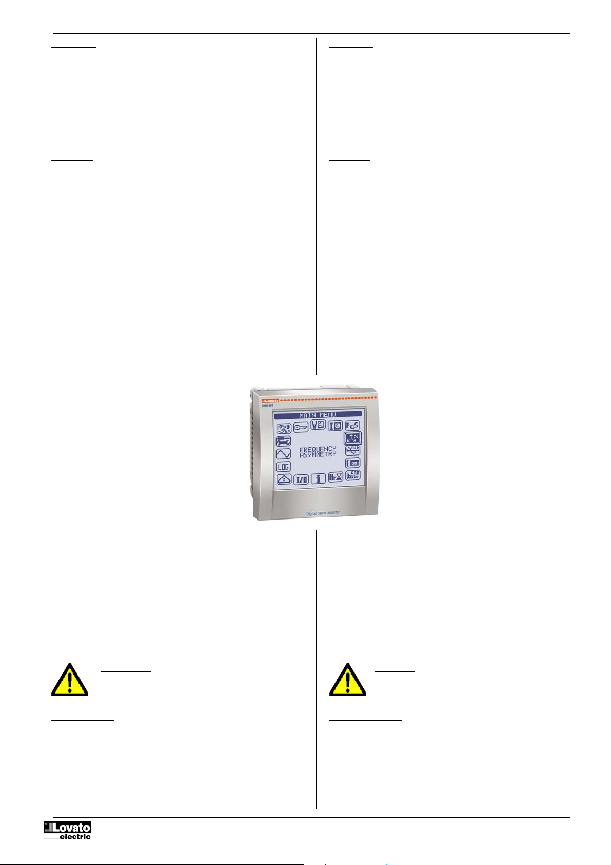
11 FREQUENZA – ASIMMETRIA
F, ASY(VLL), ASY(VLN), ASY(I) HI LO AV
12 DIST. ARMONICA TENSIONI L-L
THD-V(L1-L2), THD-V(L2-L3), THD-V(L3-L1) HI LO AV GR
13 ANALISI ARM. TENSIONI L-L
H2…63 V(L1-L2)-V(L2-L3)-V(L3-L1)
14 FORMA D’ONDA TENSIONI L-L L1-L2 L2-L3L3-L1
15 DIST. ARMONICA TENSIONI L-N
THD-V(L1),THD-V(L2),THD-V(L3) HI LO AV GR
16 ANALISI ARMONICA TENSIONI L-N
H2…63 V(L1)-V(L2)-V(L3)
17 FORMA D’ONDA TENSIONI L-N L1-N L2-N L3-N
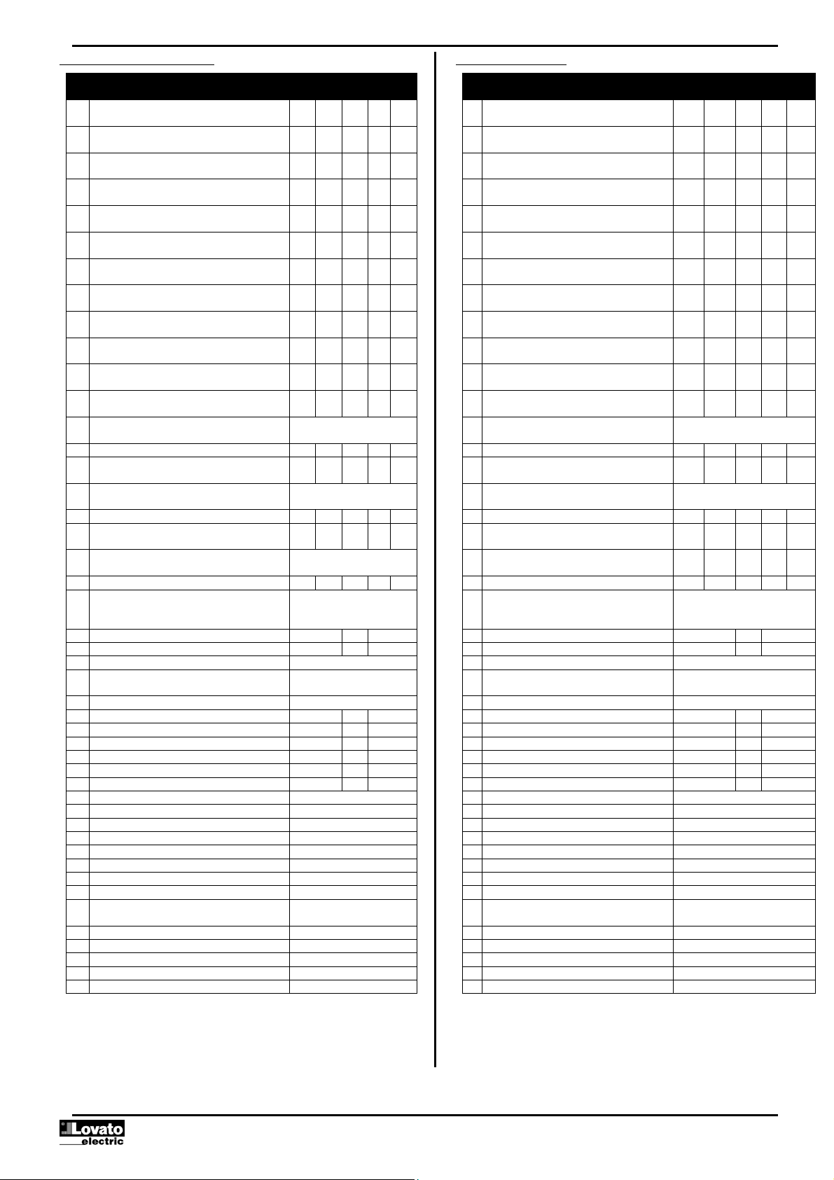
18 DIST. ARMONICA CORRENTE
THD-I(L1), THD-I(L2) THD-I(L3) HI LO AV GR
19 ANALISI ARMONICA CORRENTE
H2…63 I(L1)-I(L2)-I(L3)
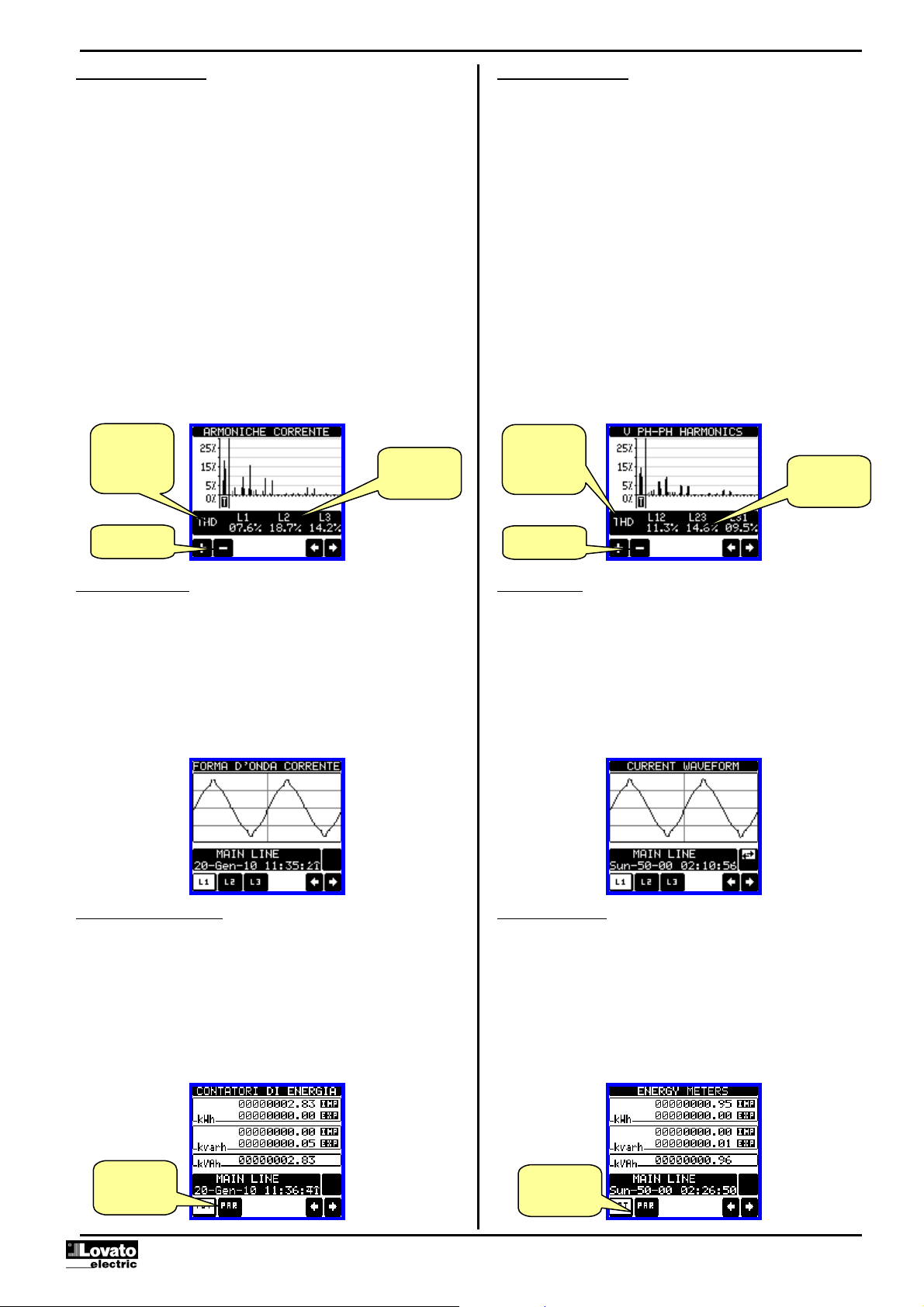
20 FORMA D’ONDA CORRENTE L1 L2 L3 N
21
CONTATORI DI ENERGIA
kWh+(TOT), kWh-(TOT), kvarh+(TOT), kvarh-
(TOT), kVA(TOT)
PARZIALI
22 TARIFFAZIONE ENERGIA TAR1 … TAR8
23 CONSUMO MENSILE ENERGIA GEN … DIC
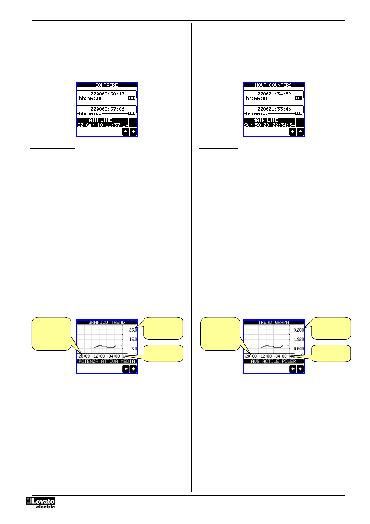
24 GRAFICO TREND
25 CONTAORE
Hr(TOT), Hr(Parziale)
26 MODULI ESPANSIONE
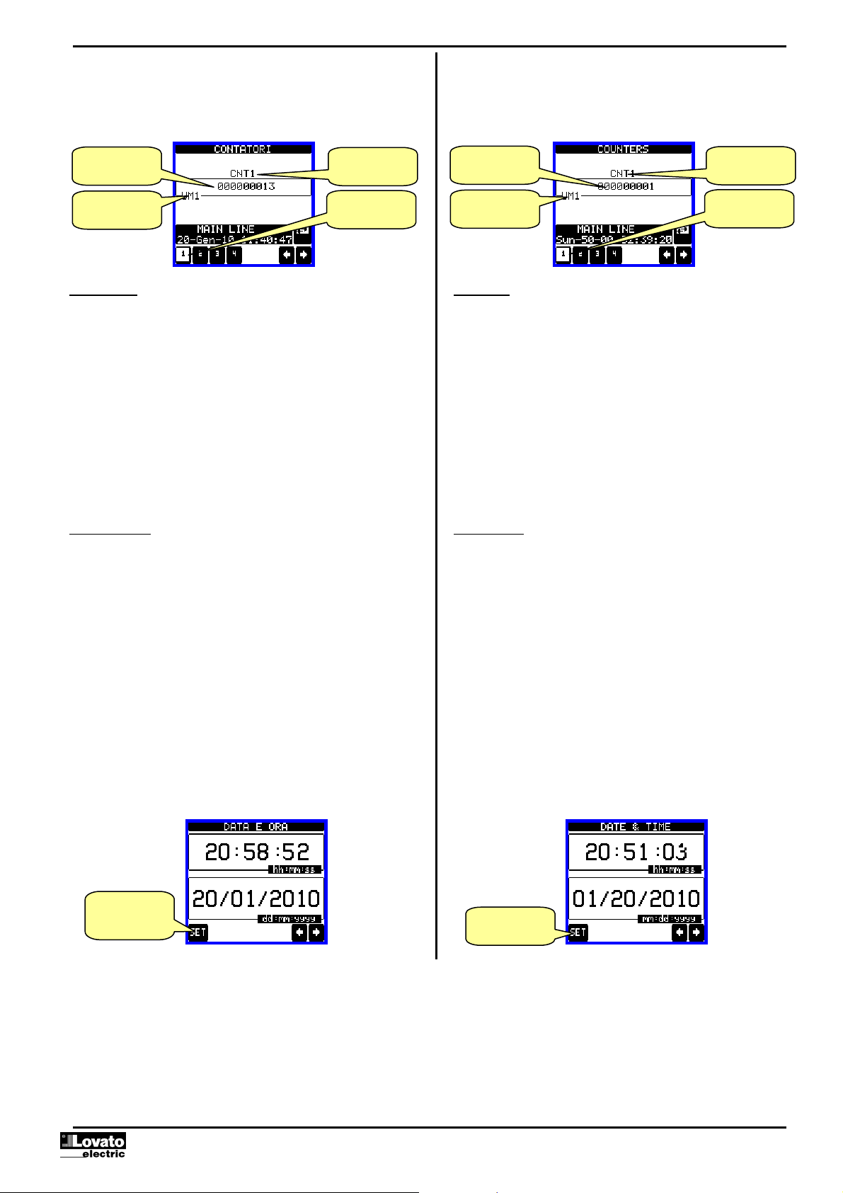
27 CONTATORI CNT1 … CNT4
28 INGRESSI ANALOGICI AIN1 … AIN8
29 USCITE ANALOGICHE AOU1 … AOU8
30 SOGLIE LIMITE LIM1 … LIM16
31 LOGICA BOOLEANA BOO1 … BOO8
32 ALLARMI ALA1 … ALA16
33 EVENTI EVENTI 1…100
34 RACCOLTA DATI
35 QUALITA’ ENERGIA SETTIMANALE SETT 1..52 / ULTIMA
36 QUALITA’ ENERGIA MENSILE
37 QUALITA’ ENERGIA ANNUALE
38 CONTATORI QUALITA’ ENERGIA
39 CATTURA FORME D’ONDA Q.E. ONDA 1..10
40 DATA E ORA
41 INFO-REVISIONI-SERIAL NR.
MODELLO,REV SW, REV HW,Nr. SERIE
42 LOGO
PAGINA UTENTE 1
PAGINA UTENTE 2
PAGINA UTENTE 3
PAGINA UTENTE 4
•Nota: Alcune delle pagine elencate sopra potrebbero non essere
visualizzate, se la funzione visualizzata non è abilitata. Ad esempio se non
viene programmato alcun allarme, la corrispondente pagina non viene
visualizzata.
Table of display pages
Selection with §and ¨Selection with icons
Nr PAGES SUB-PAGES
1 VOLTAGE - CURRENT
V(L1-L2), V(L2-L3), V(L3-L1), I(L1), I(L2), I(L3)
HI LO AV
2 PHASE-TO-PHASE VOLTAGES
V(L1-L2), V(L2-L3), V(L3-L1), V(LL)EQV HI LO AV GR
3 PHASE-TO-NEUTRAL VOLTAGES
V(L1-N), V(L2-N), V(L3-N), V(L-N)EQV HI LO AV GR
4 PHASE AND NEUTRAL CURRENTS
I(L1), I(L2), I(L3), I(N) calculated HI LO AV MD GR
5 ACTIVE POWER
P(L1), P(L2), P(L3), P(TOT) HI LO AV MD GR
6 REACTIVE POWER
Q(L1), Q(L2), Q(L3), Q(TOT) HI LO AV MD GR
7 APPARENT POWER
S(L1), S(L2), S(L3), S(TOT) HI LO AV MD GR
8 POWER FACTOR
PF(L1),PF(L2),PF(L3),PF(EQ) HI LO AV GR
9 COS-PHI
COS-PHI(L1), COS-PHI(L2), COS-PHI(L3) HI LO AV GR
10 NEUTRAL
V(N-GND), I(N), THD-I (N) HI LO AV GR
11 FREQUENCY-ASYMMETRY
F, ASY(VLL), ASY(VLN), ASY(I) HI LO AV
12 PH-PH VOLTAGE HARMONIC DISTORTION
THD-V(L1-L2), THD-V(L2-L3), THD-V(L3-L1) HI LO AV GR
13 PH-PH VOLTAGE HARMONIC ANALYSIS
H2…63 V(L1-L2)-V(L2-L3)-V(L3-L1)
14 PH-PH VOLTAGE WAVEFORMS L1-L2 L2-L3 L3-L1
15 PH-N VOLTAGE HARMONIC DISTORTION
THD-V(L1),THD-V(L2),THD-V(L3) HI LO AV GR
16 PH-N VOLTAGE HARMONIC ANALYSIS
H2…63 V(L1)-V(L2)-V(L3)
17 PH-N VOLTAGE WAVEFORMS L1-N L2-N L3-N
18 CURRENT HARMONIC DISTORTION
THD-I(L1), THD-I(L2) THD-I(L3) HI LO AV GR
19 CURRENT HARMONIC ANALYSIS
H2…63 I(L1)-I(L2)-I(L3)
20 CURRENT WAVEFORMS L1 L2 L3 N
21
ENERGY METERS
kWh+(TOT), kWh-(TOT), kvarh+(TOT), kvarh-
(TOT), kVA(TOT)
PARTIAL
22 ENERGY TARIFFS TAR1 … TAR8
23 MONTHLY ENERGY CONSUMPTION JAN … DEC
24 TREND GRAPH
25 HOUR COUNTER
Hr(TOT), Hr(Partial)
26 EXPANSION MODULES
27 COUNTERS CNT1 … CNT4
28 ANALOG INPUTS AIN1 … AIN8
29 ANALOG OUTPUTS AOU1 … AOU8
30 LIMIT THRESHOLDS LIM1 … LIM16
31 BOOLEAN LOGIC BOO1 … BOO8
32 ALARMS ALA1 … ALA16
33 EVENTS EVNT1…100
34 DATA LOGGER
35 WEEKLY ENERGY QUALITY WEEKS 1..52 / LAST
36 MONTHLY ENERGY QUALITY
37 YEARLY ENERGY QUALITY
38 ENERGY QUALITY COUNTERS
39 ENERGY QUALITY WAVEFORM CAPTURE WAVE 1..10
40 TIME AND DATE
41 INFO-REVISION-SERIAL NO..
MODEL, REV SW, REV HW, SER. No.
LOGO
USER-DEFINED PAGE 1
USER-DEFINED PAGE 2
USER-DEFINED PAGE 3
USER-DEFINED PAGE 4
•Note: Some of the pages listed above may not be available if the function
that they must view is not enabled. For instance, if no alarms have been
defined, then the Alarm page will not be shown.

Doc: MHIT104B0208.doc 20/07/2010 p. 6 / 30
Pagina analisi armonica
•Nel DMG900 è disponibile l’analisi armonica fino al 63.mo ordine (7.mo
ordine se frequenza = 400Hz) delle seguenti misure:
otensioni concatenate
otensioni di fase
ocorrenti di fase e di neutro
•Per ognuna di queste misure è disponibile una pagina che rappresenta
graficamente il contenuto armonico (spettro) tramite un istogramma a
barre.
•Ciascuna colonna rappresenta un ordine delle armoniche, pari e dispari.
La prima colonna rappresenta il contenuto armonico totale (THD).
•Ciascuna colonna dell’istogramma è poi divisa in tre parti che
rappresentano il contenuto armonico delle tre fasi L1,L2,L3.
•Il valore del contenuto armonico è espresso in percentuale riferita alla
ampiezza della armonica fondamentale (frequenza di sistema).
•E’ possibile visualizzare il valore del contenuto armonico di un certo
ordine in forma numerica, selezionando l’ordine desiderato tramite i
pulsanti + e -. In basso vengono visualizzati una freccetta che punta alla
colonna e il contenuto armonico percentuale delle tre fasi.
•La scala verticale del grafico viene selezionata automaticamente fra
quattro valori di fondoscala, in base alla colonna con il valore più alto.
Harmonic analysis page
•The DMG900 provides the harmonic analysis up to the 63rd order (7th
order if frequency = 400Hz) of the following measurements:
ophase-to-phase voltages
ophase-to-neutral voltages
ophase and neutral currents
•For each of these measurements, there is a display page that
graphically represents the harmonic content (spectrum) through a bar
graph.
•Every column is related to one harmonic order, even and odd. The first
column shows the total harmonic distortion (THD).
•Every histogram bar is then divided into three parts, one each phase
L1,L2, L3.
•The value of the harmonic content is expressed as a percentage with
respect to the fundamental (system frequency).
•It is possible to show the harmonic content in numeric format, selecting
the required order through + -. The lower part of the screen will display
a little arrow that points to the selected column, and the relative
percentage value of the three phases.
•The vertical scale of the graph is automatically selected among four
full-scale values, depending on the column with the highest value.
Pagina forme d’onda
•Questa pagina rappresenta graficamente la forma d’onda dei segnali di
tensione e di correnti letti dal DMG900.
•E’ possibile vedere una fase per volta, selezionandola cliccando
sull’icona della fase desiderata.
•La scala verticale (ampiezza) è regolata automaticamente in modo da
visualizzare al meglio possibile il segnale.
•Sull’asse orizzontale (tempo) vengono visualizzati 2 periodi consecutivi
riferiti alla frequenza attuale.
•Il grafico viene aggiornato automaticamente ogni 1 s circa.
Waveform page
•This page graphically views the waveform of the voltage and current
signals read by the DMG900.
•It is possible to see one phase at a time, selecting it by clicking on the
icon with the desired phase.
•The vertical scale (amplitude) is automatically scaled in order to fit the
waveform on the screen in the best possible way.
•The horizontal axis (time) shows two consecutive periods referred to
the fundamental frequency.
•The graph is automatically updated about every 1s.
Pagina contatori di energia
•Nella pagina contatori di energia vengono visualizzati
contemporaneamente:
oenergia attiva importata ed esportata
oenergia reattiva importata ed esportata (induttiva / capacitiva)
oenergia apparente
•La pagina principale visualizza i contatori totali. Tramite le apposite icone
è possibile passare alla sotto-pagina con i contatori parziali (azzerabili
dall’utente).
•Per l’azzeramento dei contatori è necessario accedere al menu comandi.
Energy meters page
•The Energy meters page shows the following meters simultaneously:
oactive energy, Imported and exported
oreactive energy, imported and exported (inductive / capacitive)
oapparent energy.
•The main page shows the total meters. Clicking on the dedicated
icons, the display moves to sub-page with partial meters (clearable by
the user).
•To clear energy meters, it is necessary to access the commands
menu.
Valori numerici
dell’ordine
selezionato
Numeric values
of the selected
order
Ordine delle
armoniche
selezionato
THD – 2..63
Selezione ordine
armoniche
Selectd
harmonic order
THD – 2..63
Selection of the
harmonic order
Selezione ed
indicazione
Totali / Parziali
Total / Partial
selection and
indication

Doc: MHIT104B0208.doc 20/07/2010 p. 7 / 30
Pagina contaore
•Nella pagina contaore vengono visualizzati:
ocontatore totale (conta il tempo di alimentazione dell’apparecchio)
ocontaore parziale (conta il tempo per cui una condizione
programmabile è verificata)
•Per l’azzeramento dei contatori è necessario accedere al menu comandi.
•La pagina contaore può essere disabilitata completamente se
l’abilitazione generale contaore viene impostata su OFF (vedere menu
Contaore)
Hour counters page
•The Hour counters page shows the following meters simultaneously:
ototal hour meter (counts the power-on time of the device)
opartial hour meter (counts how long a programmable condition
has been true)
•To clear hour counters, it is necessary to access the Commands
menu.
•The hour counter page can be completely hidden if the general hour
counter enable has been set to OFF (see Hour counter menu).
Pagina grafico trend
•La pagina trend consente di visualizzare un grafico con l’andamento nel
tempo di una misura definita dall’utente, selezionabile fra:
otensione equivalente integrata
opotenza attiva totale integrata
opotenza reattiva totale integrata
opotenza apparente totale integrata
•Di default, la misura visualizzata è la potenza attiva totale integrata. Per
modificare la misura, agire sull’apposito parametro nel menu di
impostazioni Trend.
•E’ possibile rappresentare sul grafico gli ultimi 96 valori della misura
integrata, ciascuno corrispondente ad un intervallo di tempo di
integrazione.
•L’intervallo di tempo di default è 15 minuti, cosicché il grafico ha la
possibilità di visualizzare l’andamento della misura selezionata nelle
ultime 24 ore.
•Con le impostazioni di fabbrica quindi il grafico trend ha la possibilità di
visualizzare l’andamento dei consumi di potenza attiva nelle ultime 24
ore.
•I dati dei consumi vengono azzerati quando si disalimenta l’apparecchio
oppure quando si agisce sul menu impostazioni.
•Superata la capacità massima di visualizzazione, i nuovi dati
sostituiscono i più vecchi, secondo una logica di memorizzazione
circolare.
•Il fondoscala verticale viene calcolato automaticamente in funzione dei
dati nominali inseriti nel menu impostazioni Generale.
Trend graph page
•The trend graph page allows to show the changes in the time domain
of one measurement selectable among the following:
oaverage equivalent voltage
oaverage total active power
oaverage total reactive power
oaverage total apparent power.
•The default measurement is the Average total active power. To change
the measurement, enter the dedicated menu parameter in the Trend
sub-menu.
•It is possible to see, on the graph, the history of the last 96 values of
the integrated measurement, each correspondent to a integration time
interval.
•The default time interval is equal to 15 minutes, so the graph depth in
time is equal to 24h.
•With the default factory setting, the trend graph shows the active
power demand variation of the last day.
•The consumption data is lost when auxiliary power is removed from the
DMG device or when the settings in the setup menu are changed.
•When the maximum storing capacity is exceeded, the newest data will
overwrites the oldest, so that the most recent data is always shown.
•The vertical full-scale is calculated automatically, depending on the
measurement selected and the highest value recorded in the Setup
menu.
Pagina contatori
•Nella pagina contatori vengono visualizzati i conteggi CNT1…4.
•E’ possibile contare il numero di volte che un ingresso viene attivato,
oppure un limite viene superato ecc. La condizione è definita dai
parametri Sorgente di conteggio.
•Per ciascun contatore è possibile definire una descrizione ed una unità
di misura tramite un testo libero, ad esempio litri, mc, ecc.
•Inoltre si può definire un coefficiente di conversione fra il numero di
impulsi conteggiati e la misura mostrata sul display. Questa funzione si
ottiene specificando un coefficiente moltiplicativo ed uno frazionario. Ad
esempio impostando k moltiplicativo = 3, per ogni impulso letto verrà
incrementato di 3 il valore indicato a display. Se invece si programma un
coefficiente frazionario = 10, la misura visualizzata verrà incrementata
solo dopo 10 impulsi applicati all’ingresso. Con la combinazione di k
moltiplicativo e frazionario si può ottenere qualsiasi rapporto di
conversione.
Counters page
•The counters page displays CNT1…4 counters.
•It is possible to count the number of times an input is activated, or a
limit has been overcame etc. The count condition is defined by
Counter source parameters.
•For every counter, it is possible to define a description and a unit of
measure with a free text, for instance litres, kg, etc.
•It is possible to define a conversion factor between the number of
pulse counts and the measurement shown on display. This function
can be obtained by specifying a multiply and a divide factor. For
instance, setting the multiplier k to 3, for every pulse count, the value
shown will be incremented 3 times. If instead, a divider is set to 10,
then the value will be incremented by one only after 10 pulses have
been applied to the input. With a combination of multiply and divide
factor, any ratio between counts and measurement can be achieved.
•If the counter has no divide factor, the screen will indicate the counter
Scala verticale.
Può essere
automatica o fissa
Scala dei tempi.
Indica il tempo nel
passato al quale si
riferiscono le
misure Misura
rappresentata
Vertical scale. Can
be auto ranging or
fixed by the user
Time scale.
Indicates the time
in the past to which
the measurements
are referred Measurement
shown on graph

Doc: MHIT104B0208.doc 20/07/2010 p. 8 / 30
•Se il contatore non ha alcun coefficiente frazionario, allora la sua
visualizzazione sarà solo con numeri interi. Altrimenti verranno
visualizzate due cifre decimali.
•I contatori possono essere azzerati tramite il menu comandi, oppure
tramite il segnale Sorgente di reset definito dagli appositi parametri.
without fractional digits, otherwise the counter will be displayed with
two decimal digits.
•The counters can be cleared by means of commands menu or by
means of the Reset source signal, defined by dedicated parameters.
Pagine utente
•L’utente ha la possibilità di creare un numero massimo di 4 pagine
personalizzate.
•Queste pagine possono contenere 4 misure ciascuna scelte liberamente
fra quelle disponibili sul DMG900.
•Il titolo della pagina utente può essere specificato liberamente
dall’utente, dando ad esempio indicazione della parte di impianto servita
dal multimetro.
•Le pagine utente sono posizionate in modo da poter essere raggiunte
facilmente partendo dalla prima pagina premendo il tasto §.
•Come per tutte le altre pagine, è poi possibile programmare il multimetro
per posizionare il display su una delle pagine utente dopo che per un
certo tempo non è stato attivato il touch-screen.
•Per l’impostazione delle pagine utente vedere l’apposito menu M15 nel
capitolo impostazione parametri.
User pages
•The user can create a maximum of 4 customised display pages.
•Each of these pages can view 4 measurements, freely chosen among
the available readings of the DMG900.
•The title of the page can be freely programmed by the user, allowing,
for instance, indicating the part of the plant supervised by the
multimeter.
•The user pages are placed in a position that allows to reach them
easily starting from the first page, by pressing button §.
•Like all other pages, it is possible to set the multimeter to return
automatically to the user page after a time has elapsed without touch
screen activation.
•To define the user page, see the dedicated menu M15 in the
parameter setup chapter.
Orologio datario
•Il DMG900 gestisce un orologio datario che viene utilizzato per la
memorizzazione degli eventi e per le funzioni legate al tempo.
•Se il DMG900 è equipaggiato con un modulo di espansione dotato di
orologio datario RTC (EXP10 30 o EXP 10 31), la data e l’ora vengono
mantenuti anche senza presenza di alimentazione ausiliaria, per un
tempo max di circa 2 settimane.
•Se invece non è montato un modulo di espansione con RTC (real-time
clock), il DMG900 lavora con un orologio datario virtuale che non viene
incrementato quando manca l’alimentazione ausiliaria.
•In questo caso, è disponibile un parametro che permette di posizionarsi
direttamente sulla pagina orologio datario dopo che l’apparecchio è stato
spento e riacceso, in modo da ricordare all’utente la necessità di
verificare/aggiornare l’ora e la data.
•L’orologio datario può essere visualizzato:
•Sulla finestra ausiliaria, presente nella maggior parte delle
pagine di misura
•Sulla pagina specifica dell’orologio, dove è possibile anche
impostare l’ora-data correnti.
Time and date
•The DMG900 manages the time and date, that is used for the storage
of events and for time-related functions.
•If the DMG900 is equipped with an expansion module with RTC (real-
time clock), then the time and date are kept updated even without
auxiliary power supply, for a maximum of about 2 weeks.
•If instead no EXP module with RTC is available , then the DMG900
operates with a virtual RTC that does not update when the auxiliary
power is off.
•In this case, a dedicated parameter allows to move automatically to the
time-date setting page every time the device has been powered off
and on, in order to remind the user to verify 7 set the correct time and
date.
•The time and date can be displayed:
•On the auxiliary window, that is shown together with mosto f
the measure pages.
•On the dedicated page, where it is possible to set the current
time/date.
Nr. del contatore
selezionato
Descrizione (libera)
del contatore
Unità di misura del
contatore
Conteggio
Nr. of the selected
counter
Description
(free text)
Unit of measure
(free text)
Counter
A
ccess to date-time
setting
A
ccesso alla
impostazione
data-ora

Doc: MHIT104B0208.doc 20/07/2010 p. 9 / 30
Accesso tramite password
•La password serve per abilitare o bloccare l’accesso al menu di
impostazione ed al menu comandi.
•Per gli apparecchi nuovi di fabbrica (default), la password è disabilitata e
l’accesso è libero. Se invece le password sono state abilitate, per
ottenere l’accesso bisogna prima inserire il relativo codice di accesso
numerico.
•Per abilitare l’uso delle password e definire i codici di accesso fare
riferimento al capitolo impostazione parametri.
•Esistono due livelli di accesso, a seconda del codice inserito:
•Accesso livello utente – consente l’azzeramento dei valori
registrati ma non la modifica delle impostazioni dell’apparecchio.
•Accesso livello avanzato – stessi diritti dell’utente con in più la
possibilità di modificare le impostazioni.
•Dalla normale visualizzazione misure richiamare il menu principale
toccando la parte centrale del display, quindi selezionare l’icona
password e premere OK.
•Compare la finestra di impostazione password in figura:
Password access
•The password is used to enable or lock the access to setting menu
(setup) and to commands menu.
•For brand-new devices (factory default), the password management is
disabled and the access is free. If instead the passwords have been
enabled and defined, then to get access, it is necessary to enter the
password first, specifying the numeric code through the keypad.
•To enable password management and to define numeric codes, see
setup menu.
•There are two access levels, depending on the code entered:
•User-Level access – Allows clearing of recorded values but
not editing of setup parameters.
•Advanced access level – Same rights of the user access plus
settings editing-restoring.
•From normal viewing, recall main menu by touching the central part of
the display, then select the password icon and press OK.
•The display shows the screen in picture:
•Inserire la password, quindi premere OK .
•Quando la password inserita corrisponde alla password livello Utente o
livello Avanzato, compare il relativo messaggio di sblocco.
•Una volta sbloccata la password, l’accesso rimane abilitato fino a che:
ol’apparecchio viene disalimentato.
ol’apparecchio viene resettato (in seguito all’uscita dal menu
impostazioni).
otrascorrono più di 2 minuti senza che l’operatore tocchi alcun tasto.
•Con il tasto ESC si abbandona l’impostazione password e si esce.
•Enter numeric code, then press OK.
•If the password code entered matches the User access code or the
Advanced access code, then the correspondent unlock message is
shown.
•Once unlocked the password, the access rights last until:
othe device is powered off.
othe device is reset (after quitting the setup menu).
othe timeout period of two minutes elapses without any keystroke.
•To quit the password entry screen press ESC key.
Blocco impostazioni
•Sul DMG900 sono disponibili due dip-switch che consentono di bloccare
l’accesso alle impostazioni e alle operazioni di reset (menu comandi).
•Questi dip switch sono posizionati in modo da diventare inaccessibili una
volta montati i coprimorsetti piombabili.
•Per posizionare i dip switch:
otogliere l’alimentazione al DMG900 e rimuovere entrambi i
coprimorsetti (se montati) e la morsettiera estraibile a 8 poli
oCon l’ausilio di un piccolo cacciavite a lama piatta, posizionare I dip
switch nella configurazione voluta.
oRiposizionare morsettiere e coprimorsetti.
•L’apparecchio viene fornito con i DIP-switch configurati in posizione di
accesso consentito.
SW POS DESCRIZIONE
ON Accesso ai parametri bloccato
SW1 OFF Accesso ai parametri consentito
ON Accesso a menu comandi bloccato
SW2 OFF Accesso a menu comandi consentito
Settings Lock
•On the DMG900 there are two DIP-switches that are used to lock
the access to parameter settings and / or to reset operations
(commands menu).
•This DIP switches are placed in a way that they become
unaccessible once the sealable terminal cover is mounted.
•To change switch position:
oRemove power supply to DMG900 and remove terminal
covers (if mounted) and the 8-pole terminal block
oUsing a small flat screwdriver, move the switches in the
desired position.
oRe-assemble terminal blocks and terminal covers.
•The multimeter is supplied with the switches in unlocked position.
SW POS DESCRIZIONE
ON Parameter settings locked
SW1 OFF Parameter settings allowed
ON Commands menu access locked
SW2 OFF Commands menu access allowed

Doc: MHIT104B0208.doc 20/07/2010 p. 10 / 30
Espandibilità
•Grazie al suo bus di espansione, il DMG900 può essere espanso con dei
moduli aggiuntivi della serie EXP….
•E’ possibile collegare un massimo di 4 moduli EXP….
•I moduli EXP… supportati dal DMG900 si dividono nelle seguenti
categorie:
omoduli di comunicazione
omoduli di I/O digitale
omoduli di I/O analogico
omoduli di memoria
•Per inserire un modulo di espansione:
otogliere l’alimentazione al DMG900
orimuovere il coprimorsetto e la morsettiera estraibile a 8 poli
orimuovere uno dei coperchi protettivi degli slot di espansione
oinserire il gancio superiore del modulo nella apposita feritoia
oruotare il modulo verso il basso inserendo il connettore sul bus
opremere fino a che l’apposita clip sul lato inferiore del modulo si
aggancia a scatto
oRe-installare la morsettiera ed il coprimorsetto trasparente.
•L’ordine di inserimento dei moduli è libero.
Expandability
•Thanks to expansion bus, the DMG900 can be expanded with
EXP… series modules.
•It is possible to connect a maximum of 4 EXP… modules.
•The supported EXP modules can be grouped in the following
categories:
ocommunication modules
odigital I/O modules
oanalog I/O modules
omemory modules
•To insert an expansion module:
oremove the power supply to DMG900
oremove the terminal cover and the 8-pole terminal block
oremove the protecting cover of one of the expansion slots
oinsert the upper hook of the module into the fixing hole
orotate down the module body, inserting the connector on the
bus
opush until the bottom clip snaps into its housing
oRe-install the terminal block and the transparent terminal cover
•The modules insertion sequence is free.
•Quando un DMG900 viene alimentato, riconosce automaticamente i
moduli EXP ad esso collegati.
•Se la configurazione del sistema è diversa rispetto all’ultima rilevata (è
stato aggiunto o rimosso un modulo), l’unità base chiede all’utente di
confermare la nuova configurazione. In caso di conferma la nuova
configurazione verrà salvata e diventerà effettiva, altrimenti ad ogni
messa in tensione verrà segnalata la discordanza.
•La configurazione attuale del sistema è visualizzata nella apposita
pagina del display (moduli espansione), dove si vedono il numero, il tipo
e lo stato dei moduli collegati.
•La numerazione degli I/O viene elencata sotto ogni modulo.
•Lo stato (attivato/disattivato) degli I/O e dei canali di comunicazione
viene evidenziato con la scritta in negativo.
•When a DMG900 is powered on, it automatically recognises the EXP
modules that have been mounted.
•If the system configuration has changed with respect to the last saved,
(one module has been added or removed), the base unit asks the user
to confirm the new configuration. In case of confirmation, the new
configuration will be saved and will become effective, otherwise the
mismatch will be shown at every subsequent power-on of the
multimeter.
•The actual system configuration is shown in the dedicated page of the
display (expansion modules), where it is possible to see the number,
the type and the status of the modules.
•The I/O numbering is shown under each module.
•The status (energised/de-energised) of every single I/O and
communication channel is highlighted in reverse
Numerazione e
stato degli I/O
Tipo dei moduli di
espansione
Numbering and
status of the I/O
Type of the
expansion module
No. and status of
communication
channel
Numero e stato dei
canali di
comunicazione
ATTENZIONE!
●Quando vengono installati dei moduli EXP… su dei
multimetri della serie DMG, è obbligatorio installare i
coprimorsetti piombabili forniti con il multimetro.
WARNING!
•When the EXP.. module is installed on a DMG series
multimeter, it is mandatory to install the sealable
terminal block covers supplied with the multimeter.

Doc: MHIT104B0208.doc 20/07/2010 p. 11 / 30
Risorse aggiuntive
•I moduli di espansione forniscono delle risorse aggiuntive che possono
essere sfruttate tramite gli opportuni menu di impostazione.
•I menu di impostazione che riguardano le espansioni sono disponibili
anche se i moduli non sono fisicamente presenti.
•Dato che è possibile aggiungere più moduli della stessa tipologia (ad
esempio due interfacce di comunicazione) i relativi menu di impostazione
sono multipli, identificati da un numero progressivo.
•Di seguito una tabella che indica quanti moduli di ogni tipo possono
essere montati contemporaneamente.
TIPO MODULO CODICE FUNZIONE Nr. MAX
EXP 10 10 USB
EXP 10 11 RS-232
EXP 10 12 RS-485
EXP 10 13 Ethernet
COMUNICAZIONE
EXP 10 14 Profibus® DP
2
EXP 10 00 4 INGRESSI 4
EXP 10 01 4 USCITE
STATICHE
4
EXP 10 02 2 INGRESSI +
2 USCITE ST.
4
I/O DIGITALI
EXP 10 03 2 RELE’ 4
EXP 10 04 2 INGRESSI
ANALOGICI
4I/O ANALOGICI
EXP 10 05 2 USCITE
ANALOGICHE
4
EXP 10 30 MEMORIA DATI +
OROLOGIO
1
MEMORIA
EXP 10 31 MEMORIA DATI,
OROLOGIO,
QUALITA’
ENERGIA
1
Additional resources
•The expansion modules provide additional resources that can be used
through the dedicated setup menus.
•The setup menus related to the expansions are always accessible, even
if the expansion modules are not physically fitted.
•Since it is possible to add more than one module of the same typology
(for instance two communication interfaces), the setup menus are
multiple, identified by a sequential number.
•The following table indicates how many modules of each group can be
mounted at the same time.
MODULE TYPE CODE FUNCTION MAX Nr.
EXP 10 10 USB
EXP 10 11 RS-232
EXP 10 12 RS-485
EXP 10 13 Ethernet
COMMUNICATION
EXP 10 14 Profibus® DP
2
EXP 10 00 4 INPUTS 4
EXP 10 01 4 STATIC
OUTPUTS
4
EXP 10 02 2 INPUTS +
2 ST. OUTPUTS
4
DIGITAL I/O
EXP 10 03 2 RELAYS 4
EXP 10 04 2 ANALOG
INPUTS
4ANALOG I/O
EXP 10 05 2 ANALOG
OUTPUTS
4
EXP 10 30 DATA MEMORY +
REAL TIME
CLOCK
1
MEMORY
EXP 10 31 DATA MEMORY,
REAL TIME
CLOCK,
ENERGY QUALITY
1
Canali di comunicazione
•Al DMG900 è possibile connettere al massimo 2 moduli di
comunicazione, denominati COMn. Il menu di impostazione
comunicazioni M07 prevede quindi due sezioni (n=1 e n=2) di parametri
per l’impostazione delle porte di comunicazione.
•I canali di comunicazione sono completamente indipendenti, sia dal
punto di vista hardware (tipo di interfaccia fisica) che dal punto di vista
del protocollo di comunicazione.
•I canali di comunicazione possono funzionare contemporaneamente.
•Attivando la funzione Gateway, è possibile avere un DMG900
equipaggiato con una porta Ethernet ed una porta RS485, che fa da
‘ponte’ verso altri DMG dotati della sola porta RS-485, in modo da
ottenere un risparmio (1 solo punto di accesso Ethernet).
In questa rete, il DMG dotato di due porte di comunicazione avrà il
parametro della funzione Gateway impostato su ON per entrambi i canali di
comunicazione (COM1 e COM2), mentre gli altri DMG saranno configurati
normalmente con Gateway = OFF.
Communication channels
•The DMG900 supports a maximum of 2 communication modules,
indicated as COMn. The communication setup menu M07 is thus
divided into two sections (n=1 and n = 2) of parameters for the setting of
the ports.
•The communication channels are completely independent, both for the
hardware (physical interface) and for the communication protocol.
•The two channels can communicate at the same time.
•Activating the Gateway function it is possible to use a DMG900 with
both an Ethernet port and a RS485 port, that acts as a bridge over other
DMGs equipped with RS-485 only, in order to achieve a more economic
configuration (only one Ethernet port).
•In this network, the DMG with two communication ports will be set with
both communication channels (COM1 and COM2) with Gateway
parameter set to ON, while the other DMGs will be configured normally
with Gateway = OFF.
Ingressi, uscite, variabili interne, contatori, ingressi analogici
•Gli ingressi e le uscite digitali forniti dai moduli di espansione sono
identificati da una sigla e da un numero progressivo. Ad esempio gli
ingressi digitali sono denominati INPx, dove x rappresenta il numero
dell’ingresso. Allo stesso modo, le uscite digitali sono denominate OUTx.
•La numerazione degli ingressi / uscite si basa semplicemente sulla
posizione di montaggio dei moduli di espansione, con una numerazione
progressiva da sinistra a destra. Ad esempio l’ingresso INP1 è il
morsetto di ingresso più vicino al modulo base, mentre i successivi
preseguendo verso destra saranno INP2, INP3 ecc.
•Per il DMG900 sono previsti un massimo di 16 ingressi digitali e di 16
uscite, che saranno quindi denominati INP1…INP16 e OUT1…OUT16.
Per ciascun I/O esiste un menu di impostazione che consente di
specificarne la funzione e le proprietà.
•Allo stesso modo degli ingressi/uscite, esistono delle variabili interne (bit)
Inputs, outputs, internal variables, counters, analog inputs
•The inputs and outputs of the expansion modules are identified by a
code and a sequence number. For instance, the digital inputs are
identified by code INPx, where x is the number of the input. In the same
way, digital outputs are identified by code OUTx.
•The sequence number of I/Os is simply based on their mounting
position, with a progressive numbering from left to right. For instance
the input INP1 is the input terminal closest to the base unit, while the
subsequent inputs will be named INP2, INP3 and so on.
•The DMG900 supports a maximum of 16 digital inputs and 16 outputs
that will thus be numbered INP1…16 and OUT1…16. For every I/O,
there is a dedicated setting menu that allows specifying functionality
and properties.
•In a similar way, there are some internal bit-variables (markers) that can
be associated to the outputs or combined between them. For instance,

Doc: MHIT104B0208.doc 20/07/2010 p. 12 / 30
che possono essere associate alle uscite o combinate fra loro. Ad
esempio si possono applicare delle soglie limite alle misure effettuate dal
multimetro (tensione, corrente etc.). In questo caso la variabile interna,
denominata LIMx, sarà attivata quando la misura risulta essere fuori dai
limiti definiti dall’utente tramite il relativo menu di impostazione.
•Inoltre sono disponibili fino a 4 contatori (CNT1…CNT4) che possono
conteggiare impulsi provenienti dall’esterno (quindi da ingressi INPx)
oppure il numero di volte per cui si è verificata una determinata
condizione. Ad esempio definendo una soglia LIMx come sorgente di
conteggio, sarà possibile contare quante volte una misura ha superato
un certo valore.
•Infine è possibile gestire fino a 8 ingressi analogici provenienti da sensori
esterni (misure di temperatura, consumo, pressione, portata ecc). Il
valore letto dagli ingressi analogici può essere convertito in qualsiasi
unità ingegneristica, visualizzato sul display e reso disponibile sul bus di
comunicazione. Le grandezze lette attraverso gli ingressi analogici sono
visualizzate sulla apposita pagina. Su di esse possono essere applicate
delle soglie limite LIMx.
•Di seguito una tabella che raccoglie tutti gli I/O e le variabili interne gestiti
dal DMG900.
COD DESCRIZIONE CAMPO
INPx Ingressi digitali 1…16
OUTx Uscite digitali 1…16
LIMx Soglie limite 1…16
BOOx Combinazioni Booleane 1…8
REMx Variabili da remoto 1…8
ALAx Allarmi 1…16
PULx Impulsi di conteggio energia 1…5
CNTx Contatori 1…4
AINx Ingressi analogici 1…8
AOUx Uscite analogiche 1…8
•Lo stato di ciascun I/O e variabile interna può essere visualizzato sul
display nella apposita pagina di stato I/O.
it is possible to apply some limit thresholds to the measurements done
by the multimeter (voltage, current, power, etc.). In this case, an internal
variable named LIMx will be activated when the measurements will go
outside the limits defined by the user through the dedicated setting
menu.
•Furthermore, there are up to 4 counters (CNT1..CNT4) that can count
pulses coming from an external source (through a digital input INPx) or
the number of times that a certain condition as been verified. For
instance, defining a limit threshold LIMx as the count source, it will be
possible to count how many times one measurement has exceeded a
certain limit.
•Finally it is possible to manage up to 8 analog inputs, connected to
external analog sensors (temperature, pressure, flow etc). The value
read from the sensors can be scaled to any unit of measure, visualized
on the display and transmitted on the communication bus. The value
read from analog inputs is shown on the dedicated display page. They
can be used to drive LIMx limit thresholds.
•The following table groups all the I/O and the internal variables
managed by the DMG900.
CODE DESCRIPTION RANGE
INPx Digital inputs 1…16
OUTx Digital outputs 1…16
LIMx Limit thresholds 1…16
BOOx Boolean logic 1…8
REMx Remote-controlled variables 1…8
ALAx Alarms 1…16
PULx Energy count pulses 1…5
CNTx Counters 1…4
AINx Analog inputs 1…8
AOUx Analog outputs 1…8
The status of each I/O or internal variable can be shown on the display in
the dedicated page.
Soglie limite (LIM)
•Le soglie limite LIMn sono delle variabili interne il cui stato dipende dalla
fuoriuscita dai limiti definiti dall’utente da parte di una misura fra quelle
effettuate dal multimetro (esempio: potenza attiva totale superiore a
25kW).
•Per velocizzare l’impostazione delle soglie, che possono spaziare in un
range estremamente ampio, ciascuna di esse va impostata con un
valore base + un coefficiente moltiplicativo (esempio: 25 x 1k = 25000).
•Per ogni LIM sono disponibili due soglie (superiore ed inferiore). La
soglia superiore deve essere sempre impostata ad un valore maggiore di
quella inferiore.
•il significato delle soglie dipende dalle seguenti funzioni:
Funzione Min: con la funzione Min la soglia inferiore è quella d’intervento
mentre quella superiore è di ripristino. Quando il valore della misura
selezionata è sotto il limite inferiore, dopo il ritardo si ha l’attivazione della
soglia. Quando il valore della misura è maggiore della soglia superiore,
dopo il ritardo si ha il ripristino.
Funzione Max: con la funzione Max la soglia superiore è quella
d’intervento mentre quella inferiore di ripristino. Quando il valore della
misura selezionata è maggiore della superiore, dopo il ritardo si ha
l’attivazione della soglia. Quando il valore della misura è minore della
soglia inferiore, dopo il ritardo si ha il ripristino.
Funzione Min+Max: con la funzione Min+Max le soglie inferiore e
superiore sono entrambe d’intervento. Quando il valore della misura
selezionata è minore della soglia inferiore o maggiore della soglia
superiore, dopo i rispettivi ritardi si ha l’intervento dell’uscita. Quando il
valore della misura rientra nei limiti si ha il ripristino immediato
•L’intervento può significare eccitazione o diseccitazione del limite LIMn a
seconda dell’impostazione .
•Se il limite LIMn è impostato con memoria, il ripristino è manuale e può
essere effettuato tramite il comando apposito nel menu comandi.
•Vedere il menu di impostazione M08.
Limit thresholds (LIM)
•The LIMn thresholds are internal variables whose status depends on
the out-of-limits of one particular measurement set by the user (e.g.
total active power higher than 25kW) among all those measured.
•To make the setting of the thresholds easier, since the limits can span
in a very wide range, each of them can be set using a base number and
a multiplier (for example: 25 x 1k = 25000).
•For each LIM, there are two thresholds (upper and lower). The upper
threshold must always be set to a value higher than the lower threshold.
•The meaning of the thresholds depends on the following functions:
Min function: the lower threshold defines the trip point, while the upper
threshold is for the resetting. The LIM trips when the selected
measurement is less than the Lower threshold for the programmed delay.
When the measured value becomes higher than the upper setpoint, after
the delay, the LIM status is reset.
Max function: the upper threshold defines the trip point, while the lower
threshold is for the resetting. The LIM trips when the selected
measurement is more than upper threshold for the programmed delay.
When the measured value decreases below the lower setpoint, after the
delay, the LIM status is reset.
Max+Min function: both thresholds are for tripping. When the measured
value is less than lower or more than upper setpoints, then, after the
respective delays, the LIM will trip. When the measured value returns
within the limits, the LIM status will be immediately reset.
•Trip denotes either activation or de-activation of the LIM variable,
depending on ‘Normal status’ setting.
•If the LIMn latch is enabled, the reset can be done only manually using
the dedicated command in the commands menu.
•See setup menu M08.

Doc: MHIT104B0208.doc 20/07/2010 p. 13 / 30
Logica Booleana (BOO)
•E’ possibile creare un massimo di 8 variabili interne denominate
BOO1…8 il cui stato dipende dalla combinazione logica Booleana di
soglie limite, ingressi, uscite etc.
•Gli operandi (INP, LIM ecc.) possono essere combinati fra loro con le
seguenti operazioni logiche Booleane: AND, OR, EXOR, AND NOT, OR
NOT, EXOR NOT.
•Ogni variabile Booleana è il risultato della combinazione di massimo 4
operandi legati fra loro da tre operazioni logiche.
•Esempio: se desideriamo che la variabile BOO1 venga attivata quando
sono attivi i limiti LIM2, LIM3 e LIM4 oppure quando è attivo l’ingresso
INP1, dovremo programmare BOO1 come la combinazione di LIM2 AND
LIM3 AND LIM4 OR INP1.
•Non è necessario utilizzare tutti i 4 operandi per una combinazione
logica. Se ad esempio vogliamo solo che BOO2 sia attivo quando è
attivo INP1 oppure INP2, è possibile programmare i parametri di BOO2
come la combinazione INP1 OR INP2, lasciando le successive
operazioni logiche impostate su --- (nessuna operazione).
•La pagina display LOGICA BOOLEANA visualizza , per ciascuna
variabile BOO1..8, lo stato dei singoli operandi che sono coinvolti nella
operazione logica ed il risultato finale, cioè lo stato della variabile
Booleana selezionata.
Boolean logic (BOO)
•It is possible to create max. 8 internal variables named BOO1..8, whose
status depends on the Boolean logic combination of limit thresholds,
inputs, outputs, etc.
•The operands (INP, LIM etc) can be combined between each other with
the following Boolean operators: AND, OR, EXOR, AND NOT, OR NOT,
EXOR NOT.
•Every Boolean variable is the result of max 4 operands combined with 3
logic operations.
•Example: if one wants the Boolean variable BOO1 to be activated when
the limits LIM1, LIM2 and LIM3 are all active or when the input INP1 is
active, BOO1 must programmed as the combination of LIM2 AND LIM3
AND LIM4 OR INP1.
•It is not necessary to use all 4 operands for one Boolean variable. If for
instance, one wants BOO2 to be active when INP1 or INP2 are active,
then it is possible to program BOO2 settings with the combination INP1
OR INP2, leaving the following logic operations set to --- (no operation).
•The BOOLEAN LOGIC page displays, for every variable BOO1..8, the
status of the single operands that are involved in the logic operation and
the final result, that is the status of the selected Boolean variable.
Variabili da remoto (REM)
•DMG900 ha la possibilità di gestire un massimo di 8 variabili comandate
da remoto (REM1…REM8).
•Si tratta di variabili il cui stato può essere modificato a piacere dall’utente
tramite il protocollo di comunicazione e che possono essere utilizzate in
abbinamento alle uscite, alla logica Booleana etc.
•Esempio: usando una variabile remota (REMx) come sorgente di una
uscita (OUTx) sarà possibile attivare e disattivare liberamente un relè
tramite il software di supervisione. Questo consentirebbe di utilizzare i
relè di uscita del DMG900 per comandare dei carichi ad esempio
illuminazione o altro.
•Un altro utilizzo delle variabili REM può essere quello di abilitare o
disabilitare determinate funzioni da remoto, inserendole in una logica
Booleana in AND con ingressi o uscite.
Remote-controlled variables (REM)
•DMG900 can manage up to 8 remote-controlled variables
(REM1…REM8).
•Those are variables which status can be modified by the user through
the communication protocol and that can be used in combination with
outputs, Boolean logic, etc.
•Example: using a remote variable (REMx) as a source for an output
(OUTx), it will be possible to freely energise or de-energise one relay
through the supervision software. This allows to use the DMG900 relays
to drive lighting or similar loads.
•Another possible use of REM variables is to enable/disable other
functions remotely, inserting them into a Boolean logic in AND with
inputs or outputs.
Allarmi (ALA)
•L’utente ha la possibilità di definire un massimo di 16 allarmi
programmabili (ALA1…ALA16).
•Per ciascun allarme è possibile stabilire la sorgente, cioè la condizione
che genera l’allarme ed il testo del messaggio che deve comparire sul
display quando questa condizione si verifica.
•La condizione che genera l’allarme può essere ad esempio il
superamento di una soglia. In questo caso la sorgente sarà una delle
soglie limite LIMx.
•Se invece l’allarme deve essere visualizzato in conseguenza
dell’attivazione di un ingresso digitale esterno, allora la sorgente sarà un
INPx.
•Con lo stesso criterio è possibile abbinare ad un allarme anche
condizioni complesse risultanti dalla combinazione logica Booleana di
ingressi, soglie, etc. In questo caso si utilizzeranno le variabili Booleane
BOOx.
•Per ciascun allarme l’utente ha la possibilità di definire un messaggio
liberamente programmabile che comparirà sulla pagina stato allarmi.
Alarms (ALA)
•The user has the possibility to define a maximum of 16 programmable
alarms (ALA1…ALA16).
•For each alarm, it is possible to define the source that is the condition
that generates the alarm, and the text of the message that must appear
on the screen when this condition is met.
•The condition that generates the alarm can be, for instance, the
overcoming of a threshold. In this case, the source will be one of the
limit thresholds LIMx.
•If instead, the alarm must be displayed depending on the status of an
external digital input, then the source will be an INPx.
•With the same criteria, it is possible to also link complex conditions to
an alarm, resulting from the logic combination of inputs, limits, etc. In
this case, the Boolean logic variables BOOx must be used.
•For every alarm, the user can define a free message that will appear on
the alarm page.
•It is also possible to define a priority for the alarm. If it is a simple
Operando 1
Operaz. logica 1
Operando 2
…
Stato operando 1
Stato variabile
booleana risultante
Operand 1
Logic operation 1
Operand 2
…
Operand status 1
Status of the
resulting variable
Tipo di misura
Funzione
Valore della misura
Soglia inferiore
Type of measure
Function
Value of measure
Upper threshold
Lower threshold
Status of the limit
variable
Soglia superiore

Doc: MHIT104B0208.doc 20/07/2010 p. 14 / 30
•E’ poi possibile definire una priorità di allarme. Se si tratta di una
semplice indicazione, allora la priorità può essere impostata come
bassa. In questo caso l’icona che accompagna l’allarme sarà l’icona di
informazione.
•Se invece l’allarme deve indicare una situazione più importante,
impostando la sua priorità su alta, sarà possibile indicare il messaggio
con l’icona di attenzione e far sì che al verificarsi dell’allarme la pagina
del display si sposti automaticamente sulla pagina visualizzazione
allarmi.
•In caso di presenza di un allarme con priorità alta è possibile attivare il
buzzer con un suono intermittente, per una durata stabilita o
continuamente fino a che non viene tacitato dall’utente premendo
l’apposito tasto sulla pagina allarmi.
•In caso di presenza contemporanea di più allarmi essi vengono mostrati
a rotazione e ne viene indicato il numero totale.
•L’ icona viene visualizzata sulla finestra ausiliaria quando è attivo un
allarme.
•Per azzerare un allarme che è stato programmato con memoria,
utilizzare l’apposito comando nel menu comandi.
•Per la definizione degli allarmi vedere menu di impostazione M09.
indication, then the priority can be set to low. In this case the icon that
follows the message will be the ‘info’ symbol.
•If instead, the alarm must indicate a more critical situation, then setting
its priority to High, the message will be displayed with the ‘Warning’
icon, and when the alarm becomes active, the display page will move
automatically on the Alarm screen.
•When one alarm with high priority is present, it is possible to activate
the buzzer with an intermittent sound, for a defined period of time or as
long as the user acknowledges it with the dedicated button on the alarm
page.
•When several alarms are active at the same time, they are displayed
sequentially, and their total number is shown on the status bar.
•The icon is shown on the auxiliary window when one or more
alarms are active.
•To reset one alarm that has been programmed with latch, use the
dedicated command in the commands menu.
•For alarm programming and definition, refer to setup menu M09.
Lista eventi
•Il DMG900 può tenere memorizzata una lista di eventi, che può essere
utile all’utente per risalire alla causa di anomalie e/o per tenere traccia
del comportamento dell’impianto.
•Ciascun evento viene memorizzato con un numero sequenziale e con
data e ora.
•La memoria può contenere gli ultimi 100 eventi, dopodiché gli eventi più
vecchi vengono persi per lasciare spazio ai nuovi, secondo una logica
FIFO (buffer circolare).
•Gli eventi possono essere suddivisi in categorie, riassunte nella
seguente tabella:
TIPO EVENTO DESCRIZIONE
Alimentazione Accensione / spegnimento del DMG900
Picchi Aggiornamento di valori di HI / LO / MD
Allarmi Generazione di allarmi
Limiti Superamento di limiti impostati dall’utente
Variabili Modifica di variabili da remoto
Comunicazione Attivazione/disattivazione comunicazione
Tariffe Cambio di tariffa energetica
Impostazione Accesso ai parametri di impostazione
Comandi Utilizzo menu comandi per azzeramenti ecc.
Password Inserimento password, modifica DIP switch
Sistema Cambiamento configurazione espansioni
•E’ possibile scorrere la memoria eventi visualizzandoli sulla apposita
pagina.
•Tramite il pulsante dedicato è poi possibile attivare dei filtri in modo da
visualizzare solo un certo tipo di eventi o solo un intervallo temporale.
Event log
•The DMG900 can store a list of events, that can be useful to the user in
order to detect anomalies and/or keep track of the plant behaviour.
•Every Eventi s stored with a sequential number and relative time
stamp.
•The memory can store the last 100 events, afterwards the oldest events
are overwritten by the new ones, with a FIFO logic (circular buffer).
•Events can be grouped into categories, listed in the following table:
EVENT TYPE DESCRIPTION
Power supply Switch ON / OFF
Peaks Update of HI / LO / MD values
Alarms Alarm
Limits Overcoming of user-defined limits
Variables Change of remote-controlled variables
Communication Begin – end of remote control by serial port
Tariffs Change of energy tariff
Setting Access to setup parameters
Commands Use of command menu to reset etc.
Password Password enter, change of protection DIP-sw
System Change of expansion configuration
•E’ possibile scorrere la memoria eventi visualizzandoli sulla apposita
pagina.
•Tramite il pulsante dedicato è poi possibile attivare dei filtri in modo da
visualizzare solo un certo tipo di eventi o solo un intervallo temporale.
Nr. Allarme / totale
allarmi
A
larm nr. / total
alarm count
Numero e codice
evento
Data e ora evento
Descrizione evento
Spostamento fra gli
eventi
Numero e codice
evento
Data e ora evento
Descrizione evento
Spostamento fra gli
eventi

Doc: MHIT104B0208.doc 20/07/2010 p. 15 / 30
Tariffe
•Per il conteggio dell’energia, il DMG900 ha la possibilità di gestire 8
tariffe indipendenti oltre alla totale e alla parziale.
•La sel
•ezione delle tariffe avviene tramite degli ingressi digitali esterni, ed è
quindi condizionata all’installazione di un modulo di espansione EXP
fornito di ingressi digitali. Per selezionare le 4 tariffe sono disponibili le
tre funzioni di ingresso TAR-A/B/C. La loro combinazione binaria effettua
la selezione come da tabella:
TAR-A TAR-B TAR-C TARIFFA
OFF OFF OFF 1
ON OFF OFF 2
OFF ON OFF 3
ON ON OFF 4
OFF OFF ON 5
ON OFF ON 6
OFF ON ON 7
ON ON ON 8
•Se viene utilizzato l’ingresso di sincronismo per l’intervallo di
integrazione, allora il cambio tariffa viene effettuato in concomitanza con
il sincronismo, altrimenti il cambio di tariffa avviene al momento del
cambio di configurazione degli ingressi.
•I conteggi delle tariffe, ciascuno con i 5 contatori di energia (attiva
importata ed esportata, reattiva importata ed esportata, apparente) sono
visualizzati su una apposita pagina, consecutiva a quella dei contatori
totali e parziali .
•Se il DMG è fornito di interfaccia di comunicazione, è possibile
selezionare la tariffa attiva tramite un apposito comando sul protocollo
modbus (vedere istruzione tecnica protocollo modbus).
.
Tariffs
•For the Energy billing, the DMG900 can manage 8 different tariffs in
addition to the total and partial Energy meters.
•The tariff selection is made by external digital inputs, and is thus
conditioned by the use of an EXP expansion module provided with
digital inputs. To select among the 4 tariffs, the three input functions
TAR-A/B/C must be used. Their binary combination selects the tariff as
shown in table:
TAR-A TAR-B TAR-C TARIFF
OFF OFF OFF 1
ON OFF OFF 2
OFF ON OFF 3
ON ON OFF 4
OFF OFF ON 5
ON OFF ON 6
OFF ON ON 7
ON ON ON 8
•If the synchronise input for the power integration is used, then the tariff
change becomes active when the sync signal triggers it; otherwise the
tariff change takes place immediately when the status of the selecting
inputs changes.
•The tariffs, each with 5 meters (active energy imported/exported,
reactive imported/exported, apparent) are shown on a dedicated page,
following the total-partial energy screen.
•If the DMG is equipped with a communication port, then it is possible to
select the active tariff through the dedicated command via modbus
protocol (see technical instruction for modbus protocol).
Conteggio mensile energie
•Il DMG900 memorizza lo stato dei contatori di energia per gli ultimi 12
mesi.
•Per ciascun mese sono visualizzati i 5 contatori assoluti (kwh+, kwh-,
kvarh+, kvarh-,kVAh) e la differenza rispetto al mese precedente
(consumo mensile).
•La memorizzazione della situazione mensile avviene alle 00:00 del primo
giorno di ogni mese.
•Tramite l’apposita pagina è possibile scorrere i mesi e passare dalla
visualizzazione conteggio assoluto (TOT = valore del contatore alla fine
del mese) al consumo mensile (CON = energia consumata nel mese).
•La tabella annuale dei consumi mensili viene aggiornata ciclicamente. E’
possibile azzerarla completamente tramite l’apposito comando nel menu
comandi.
•Se un conteggio non è disponibile (tempo non ancora trascorso),
vengono visualizzati dei trattini.
Monthly energy counters
•The DMG900 stores the status of Energy counters of the last 12
months.
•For every month the unit displays the 5 total counters (kwh+, kwh-,
kvarh+, kvarh-,kVAh) and the difference with respect to the previous
month (monthly energy consumption).
•The storage of the monthly situation takes place at midnight of the first
day of each month.
•Through the dedicated monthly energies page it is possible to browse
through the months and to switch between absolute count (TOT = value
of the counter at the end of the month) and relative count (CON =
consumption in that month).
•The annual table of monthly energy is update cyclically. It is possible to
clear it completely through the dedicated command in the command
menu.
•If a count is not available (time period not elapsed yet), then some
dashes are shown.
Tariffa
visualizzata
Tariffa attiva
attualmente
Presently
active tariff
Visualized tariff
Selezione mese
Conteggi del
mese
selezionato
Selezione
TOT / CON
Selection of the
month
Counters of the
selected month
Selected
month
Selection
TOT / CON

Doc: MHIT104B0208.doc 20/07/2010 p. 16 / 30
Funzione data logger
•Per abilitare la funzione data logger il DMG deve essere equipaggiato di
un modulo di memoria EXP1030 o EXP1031.
•Per la configurazione del data logger è necessario utilizzare il software
su PC DMK-DMG data logger (codice DMKSW10), che consente di
scegliere le variabili e le modalità di registrazione nonché di scaricare i
dati sotto forma di tabella di database MS-Access ®.
•Il data logger consente di memorizzare a intervalli regolari fino a 32
variabili scelte liberamente fra le misure fornite dal multimetro.
•Per ciascuna di queste variabili è possibile scegliere se memorizzare:
1. Il valore istantaneo che la variabile aveva al momento del
campionamento.
2. Il valore medio che la variabile ha avuto nel periodo di
campionamento.
3. Il valore massimo assunto nell’intervallo di campionamento.
4. Il valore minimo assunto nell’intervallo di campionamento.
•Ciascun record viene corredato di data e ora (time stamp) prelevata
dall’orologio datario incorporato nei moduli di memoria. Il tempo minimo
di campionamento (distanza fra i record) è di 1 secondo.
•Considerando la quantità di memoria disponibile (8Mbytes), il numero di
variabili e il periodo di memorizzazione, il software fornisce una
indicazione del tempo necessario al riempimento completo della
memoria flash.
•La memorizzazione può essere continua (scandita solo dal tempo)
oppure condizionata, cioè legata all’attivarsi di una variabile (limiti,
allarmi, booleane ecc.). In questo caso è possibile definire quale variabile
comanda l’avvio/arresto della registrazione.
•Quando la memoria viene esaurita è possibile fermare la registrazione
(modo STOP) oppure lasciarla continuare sovrascrivendo i
campionamenti più vecchi (modo LOOP).
•Nella apposita pagina video dello stato del datalogger vengono
visualizzate tutte le informazioni fondamentali quali il numero di misure, il
periodo di campionamento, lo stato della registrazione, la quantità di
memoria libera, il tempo residuo prima del riempimento della memoria
(Nota: queste ultime due informazioni non sono disponibili se si lavora in
modo LOOP).
•I dati registrati dal DMG possono essere scaricati sul disco fisso del PC
tramite un modulo di interfaccia seriale.
•Per le istruzioni dettagliate sulla programmazione della funzione data
logger, fare riferimento al manuale del software DMK-DMG data logger.
•Nota: E’ obbligatorio inserire il modulo di memoria nello slot 1 del
bus espansioni del DMG (primo a sinistra).
Data logger function
•To activate the data logger function the DMG must be equipped with a
EXP1030 or EXP1031 memory module.
•To configure the data logger it is necessary to use the PC software
DMK-DMG Data logger (code DMKSW10) , that allows to select the
variables and recording modes and to download data in the form of a
MS-Access ® database table.
•The data logger allows to store at regular intervals up to 32 variables
chosen freely among the multimeter measures.
•For each one of these variables it is possible to store:
1. The instantaneous value that the variable had at the moment of
sampling.
2. The average value that the variable had in the sampling period.
3. The maximum value that the variable reached in the sampling
period.
4. The minimum value that the variable reached in the sampling
period.
•Every record is marked with a time stamp taken from the real-time clock
of built in the module. The minimum sampling period (distance between
two records) is of 1 second.
•Considering the amount of memory (8 Mbytes), the number of variables
to be stored and the sampling period, the PC software indicates the time
that must elapse before the flash memory is completely filled.
•The recording can be continuous (driven only by regular time intervals)
or conditional, driven by the status of one of the internal bit-variables
(limits, alarms, Booleans etc.). In this case it is possible to define which
variable controls the starting/stopping of the recording.
•When the memory is full, the user can choose to stop the recording
(STOP mode) or to continue overwriting the oldest records (LOOP
mode).
•The display page dedicated to the data logger status shows all the
fundamental information, like number of measures, available free
memory, residual time before the memory is filled (Note: the last two
data are not shown when working in LOOP mode).
•Data recorded by the DMG can be downloaded to the PC disk through a
serial interface module.
•For detailed information about the setting of datalogger function see the
manual of the DMK-DMG data logger software.
•Note : The memory module mandatory position is slot 1 of the
DMG expansion bus (leftmost).
Analisi qualità dell’energia
•Per abilitare la funzione qualità dell’energia il DMG900 deve essere
equipaggiato di un modulo di memoria EXP1031.
•Per la configurazione dei parametri di qualità dell’energia, fare riferimento
all’apposito menu M18 nel capitolo della programmazione parametri.
•Questa funzione consente di controllare che la tensione e la frequenza
misurate dall’analizzatore (solitamente quelle provenienti dal fornitore di
energia) rientrino nei parametri minimi di qualità dell’energia secondo le
indicazioni della norma EN 50160.
•In particolare, il DMG900 in abbinamento al modulo EXP 10 31 permette
di controllare le seguenti anomalie, ciascuna identificata da una sigla:
oVariazioni di bassa entità della tensione media integrata (VLO –
VHI)
oVariazioni di forte entità della tensione media integrata (V NLO
– V NHI)
Energy quality analysis
•The DMG900 must be equipped with EXP10 31 expansion module to
enable the energy quality function.
•Refer to the relative menu M18 in the parameters setting chapter for the
energy quality parameters configuration.
•This function permits to control that the voltage and the frequency
measured by the analyzer (normally those provided by the power
supplier) remain within the minimum energy quality parameters
according to EN 50160 standard prescriptions.
•In particular, the DMG900 coupled with the EXP10 31 module allows to
control the following phenomenon, each identified by a reference code:
oSmall variations of integrated average voltage (VLO – VHI)
oLarge variations of integrated average voltage (NLO – NHI)
oHarmonic distortion of voltage, like THD or single harmonic levels
(THD – HAR)
Mese
selezionato
Stato datalogger e
numero di misure
Stato
registrazione
di
Periodo
campionamento
di
Percentuale di
memoria libera
A
utonomia
memoria
espressa in
giorno o in
hh:mm:ss se
inferiore ad 1
giorno
Datalogger status and
number of measures
Recording
status
Sampling
period
Percentage of
free memory
Time left before
end of memory,
expressed in
days or in
hh:mm:ss if less
than 1 day.

Doc: MHIT104B0208.doc 20/07/2010 p. 17 / 30
oDistorsione armonica della tensione, come THD o come singole
armoniche (THD – HAR).
oAsimmetria delle fasi (ASY)
oVariazioni di bassa entità della frequenza (FLO – FHI)
oVariazioni di forte entità della frequenza (F NLO – F NHI)
oAbbassamenti rapidi di tensione (DIP)
oInnalzamenti rapidi di tensione (SWELL)
oInterruzioni di tensione brevi (INTERRUPTION)
oInterruzioni di tensione lunghe (INTERRUPTION > 180s)
•Le soglie massime consentite per i fenomeni sopra elencati sono
regolabili dall’utente tramite il menu M18. Di default questi limiti sono
impostati ai valori suggeriti dalla norma EN50160.
•Ciascun evento può essere disabilitato impostando la relativa soglia su
OFF.
•Per tutti i fenomeni elencati sopra, al verificarsi dell’anomalia viene
generato un evento con data e ora che rimane memorizzato nella
memoria ritenitiva in ordine cronologico. Restano memorizzati gli ultimi
100 eventi occorsi.
•Per i fenomeni ‘lenti’ cioè quelli basati sulle misure integrate (VHI-VLO-
THD-HAR-ASY-FHI-FLO) vengono conteggiate le percentuali di tempo in
cui le grandezze sono state fuori dai limiti impostati. Le percentuali
possono essere visualizzate facendo riferimento alla storia dell’ultima
settimana, di una qualsiasi settimana dell’ultimo anno, dell’ultimo mese
(ultime 4 settimane), o dell’ultimo anno.
•Per gli eventi ‘veloci’ (dip, swell, interruption) vengono invece
incrementati dei contatori che indicano quante volte questo tipo di
anomalia si è verificata a partire dalla data dell’ultimo azzeramento
(vedere menu comandi).
•I fenomeni veloci sono basati sulla misura RMS della tensione e vengono
controllati ogni mezzo ciclo della frequenza fondamentale (10ms a
50Hz).
•Esistono infine dei contatori analoghi a quelli del punto precedente
anche per i fenomeni ‘lenti’ ma di forte entità (NHI e NLO per tensione e
frequenza). Questi eventi non dovrebbero mai manifestarsi, da qui la
definizione N (never).
•Quando si abilita la funzione di controllo della qualità dell’energia,
l’intervallo di integrazione della tensione diviene automaticamente in
modalità fissa di durata 10 minuti, mentre quello della frequenza diviene
di 10 secondi.
•Per poter utilizzare la funzione analisi dell’energia l’utente deve
impostare esplicitamente i valori nominali di tensione e di frequenza,
utilizzando gli appositi parametri P01.03 e P01.08 nel menu Generale
(lasciandoli impostati su AUT la funzione qualità dell’energia non verrà
abilitata). In un sistema polifase la tensione nominale impostata si
riferisce sempre al valore della concatenata.
•E’ inoltre importante che venga specificato il tipo di collegamento (con /
senza neutro).
•Quando il controllo per la distorsione è impostato su singole armoniche
(HAR) le soglie applicate, differenziate per i vari ordini di armoniche dal
2.o al 25.mo, sono quelle definite dalla apposita tabella riportata nella
norma EN50160.
Pagina qualità energia settimanale
Pagina contatori qualità energia
oPhase asymmetry (ASY)
oSmall variations of frequency (FLO-FHI)
oLarge variations of frequency (NLO-NHI)
oSudden reduction of voltage (DIPS)
oSudden increase of voltage (SWELLS)
oBrief supply voltage interruptions (INTERRUPTIONS).
oLong supply voltage interruptions (INTERRUPTIONS).
•The maximum limit thresholds allowed for the above-indicated
phenomenon are adjustable, by the user, through menu M18. The
factory-default values of these limits are set to values specified by the
EN 50160 standard.
•The detection of each event can be disabled by setting the
correspondent threshold to OFF.
•For all the above-listed phenomenon, when an abnormality occurs, an
event with time stamp is logged and stored in the retentive memory, in
chronological order. Only the latest 100 events remain stored.
•“Slow” phenomenon, i.e. those based on integrated measurements
(VHI-VLO- THD-HAR-ASY-FHI-FLO), are counted according to the time
percentages during which they remained out of programmed limits. The
percentages can be viewed using the “LAST WEEKLY” energy quality
display page; viewing is intended to be of last week, of any week of last
year, of last month (last 4 weeks) or of the entire last year.
•Instead for “sudden” events (dip, swell, interruption), energy quality
counters are increased and indicate the number of times this type of
abnormality occurs as of the last clearing date (see commands menu).
•Dips, swells and interruptions are controlled comparing the RMS value
of the voltage and are checked every half cycle of the fundamental
frequency (e.g. every 10ms at 50Hz).
•Ultimately, there are analog counters in addition to those mentioned
above, which also record the “slow” phenomenon but with large
variations (NHI and NLO for voltage and frequency). These events
should never take place and, for this reason, the N (never) reference is
used.
•When the control function of energy quality is enabled, the integration
time for voltage is automatically programmed to 10 minutes while for
frequency to 10 seconds.
•To be able to use the energy analysis function, the user expressly must
program the rated values of voltage and frequency using the relevant
parameters P01.03 and P01.08 in the General menu. By leaving them
set to AUT, the energy quality function will not be enabled. The rated
voltage is always referred to the phase-to-phase value.
•It is also important to configure the type of wiring (P01.07), with or
without neutral.
•When the distortion control mode is set to single harmonics (HAR) the
thresholds, different for each order of harmonic from the 2nd up to 25th,
are the ones defined in the dedicated table in the EN50160 reference
standard.
Weekly Energy quality page
Energy quality Counters page
Sigla del tipo di
anomalia
Percentuale di
tempo di
presenza
dell’anomalia
Selezione della
settimana
dell’anno
Selezione fra
settimana
corrente o
passata
Numero della
settimana
Tipo di anomalia
Contatori
numero di
occorrenze
Data ultimo
azzeramento
contatori
Conteggio totale
interruzioni e
solo interruzioni
di lunga durata
Code for type of
abnormality
Percentage of
abnormality time
duration
Select the week
of the year
Select between
current or
previous week
Number of the
week
Type of
abnormality Event counters
Latest counters
clearing date

Doc: MHIT104B0208.doc 20/07/2010 p. 18 / 30
Cattura forme d’onda
Waveform Capture page
Impostazione dei parametri (setup)
•Dalla normale visualizzazione misure, premere il centro del display per
richiamare il menu principale,quindi selezionare l’icona per accedere
al menu impostazioni.
•Viene visualizzata la tabella in figura, con la selezione dei sotto-menu di
impostazione, nei quali sono raggruppati tutti i parametri secondo un
criterio legato alla loro funzione.
•Selezionare il menu desiderato tramite i tasti ▲▼e confermare con OK.
•Per uscire e tornare alla visualizzazione misure premere ESC.
Impostazione: selezione menu
•Nella seguente tabella sono elencati i sottomenu disponibili :
Cod MENU DESCRIZIONE
M01
GENERALE Dati caratteristici dell’impianto
M02
UTILITA’ Lingua, luminosità, pagine
M03
PASSWORD
A
bilitazione protezione
M04
INTEGRAZIONE Tempi di integrazione misure
M05
CONTAORE Abilitazione contaore
M06 GRAFICO TREND Definizione misura e scala
M07
COMUNICAZIONE (COMn) Porte di comunicazione
M08 SOGLIE LIMITE (LIMn) Soglie sulle misure
M09 ALLARMI (ALAn) Messaggi di allarme
M10 CONTATORI (CNTn) Contatori generici
M11 IMPULSI (PULn) Impulsi di conteggio energia
M12 LOGICA BOOLEANA (BOOn) Combinazioni logica Booleana
M13 INGRESSI (INPn) Ingressi digitali
M14 USCITE (OUTn) Uscite digitali
M15 PAGINE UTENTE (PAGn) Pagine personalizzate
M16 INGRESSI ANALOGICI (AINn) Ingressi analogici
M17 USCITE ANALOGICHE (AOUn) Uscite analogiche
M18 QUALITA’ ENERGIA Analisi qualità dell’energia
Parameter setting (setup)
•With normal viewing, press center of display to recall the General menu,
then select icon to open the setup menu screen.
•The display will show the table below, with the parameters grouped in
sub-menus with a function-related criteria.
•Select the required menu with ▲▼keys and confirm with OK.
•To quit setup and go back to the readings viewing, press ESC.
Set-up: menu selection
•The following table lists the available sub-menus:
Cod. MENU DESCRIPTION
M01 GENERAL Detailed data of the installation
M02 UTILITY Language, backlight, display
M03 PASSWORD Access codes enabling
M04 INTEGRATION Readings integration time
M05 HOUR COUNTER Hour counter enabling
M06 TREND GRAPH Trend graph reading and scale
M07 COMMUNICATION (COMn) Communication ports
M08 LIMIT THRESHOLDS (LIMn) Limit thresholds on readings
M09 ALARMS (ALAn) Alarm messages
M10 COUNTERS (CNTn) General counters
M11 ENERGY PULSING (PULn) Energy pulse count
M12 BOOLEAN LOGIC (BOOn) Boolean logic variables
M13 INPUTS (INPn) Digital inputs
M14 OUTPUTS (OUTn) Digital outputs
M15 USER PAGES (PAGn) User-defined pages
M16 ANALOG INPUTS (AINn) Analog inputs
M17 ANALOG OUTPUTS (AOUn) Analog outputs
M18 ENERGY QUALITY Energy quality analysis
•Selezionare il menu e premere il tasto OK per visualizzare i parametri.
•Tutti i parametri sono visualizzati con codice, descrizione, valore attuale.
•Select the sub-menu and press OK to show the parameters.
•Each parameter is shown with code, description and present value.
Impostazione: selezione parametri
Set-up: parameter selection
•Se si vuole modificare il valore di un parametro, dopo averlo selezionato
premere OK.
•Se non è stata immessa la password livello Avanzato, non sarà possibile
accedere alla pagina di modifica, e verrà visualizzato un messaggio di
•To modify the setting of one parameter, select it and then press OK.
•If the Advanced level access code has not been entered, it will not be
possible to enter editing page and an access denied message will be
shown.
Codice
parametro
Descrizione
parametro
Valore attuale
Parametro
selezionato
Parameter code
Parameter
description
Present setting
value
Selected
parameter
Torna alla
selezione menu Modifica
parametro
Back to menu
selection
Edit
parameter
Numero e data
di cattura della
forma d’onda su
evento
Selezione della
fase
Selezione della
forma d’onda
Number and
date of event
waveform
ca
p
ture
Phase selection Waveform
selection

Doc: MHIT104B0208.doc 20/07/2010 p. 19 / 30
accesso negato.
•Se invece si ha l’accesso, verrà visualizzata la pagina di modifica.
•If instead the access rights are confirmed, then the editing screen will
be shown.
Impostazione- pagina di modifica
Set-up: editing page
•Quando si è in modalità modifica, il valore può essere modificato con i
tasti + e -. Vengono visualizzati anche una barra grafica che indica il
range di impostazione, i valori minimi e massimi possibili, il valore
precedente e quello di default.
•Premendo il tasto DEF l’impostazione viene riportata al valore di default
di fabbrica.
•Premere ESC per tornare alla selezione parametri. Il valore immesso
rimane memorizzato.
•Premere di nuovo ESC per salvare i cambiamenti ed uscire dalla
impostazione. Il multimetro esegue un reset e ritorna in funzionamento
normale.
•Se non viene attivato il touch screen per 2 minuti consecutivi, il menu
setup viene abbandonato automaticamente e l’analizzatore torna alla
visualizzazione normale.
•When the editing screen is displayed, the parameter setting can be
modified with + and - keys. The screen shows the new setting, a
graphic bar that shows the setting range, the maximum and minimum
values, the previous setting and the factory default.
•Pressing key DEF the setting is set to factory default.
•Press ESC to go back to the parameter selection. The entered value is
stored.
•Press ESC again to save all the settings and to quit the setup menu.
The multimeter executes a reset and returns to normal operation.
•If the user does not press the touch screen for more than 2 minutes,
the analyzer leaves the setup automatically and goes back to normal
viewing.
Tabella parametri
Table of parameters
M01 – GENERALE UdM Default Range M01 – GENERAL UoM Default Range
P01.01 Primario TA A 5 1-10000 P01.01 CT primary A 5 1-10000
P01.02 Secondario TA A 5 1-5 P01.02 CT secondary A 5 1-5
P01.03 Tensione nominale V Aut Aut / 50-500000 P01.03 Rated voltage V Aut Aut / 50-500000
P01.04 Utilizzo TV OFF OFF-ON P01.04 Use VT OFF OFF-ON
P01.05 Primario TV V 100 50-500000 P01.05 VT primary V 100 50-500000
P01.06 Secondario TV V 100 50-500 P01.06 VT secondary V 100 50-500
P01.07 Tipo di collegamento L1-L2-L3-N L1-L2-L3-N
L1-L2-L3
L1-L2-L3-N BIL
L1-L2-L3 BIL
L1-N-L2
L1-N
P01.07 Wiring L1-L2-L3-N L1-L2-L3-N
L1-L2-L3
L1-L2-L3-N BIL
L1-L2-L3 BIL
L1-N-L2
L1-N
P01.08 Frequenza nominale Hz Aut Aut-50-60-400 P01.08 Rated frequency Hz Aut Aut-50-60-400
P01.09 TA su neutro (ingresso I4) ON ON-OFF P01.09 CT on neutral (I4 input) ON ON-OFF
P01.01 – Corrente nominale del primario dei TA.
P01.02 – Corrente del secondario dei TA.
P01.03 - Tensione nominale dell’impianto. Lasciando su Aut il multimetro adegua
automaticamente la scala delle barre grafiche.
P01.04 – Programmare ad ON se vengono utilizzati dei TV. Se programmato ad OFF i
successivi due parametri vengono ignorati.
P01.05 – Tensione nominale primario TV.
P01.06 – Tensione nominale secondario TV.
P01.07 – Impostare concordemente allo schema di collegamento utilizzato. Vedere
Schemi di collegamento alla fine del manuale.
P01.08 – Frequenza nominale della linea. Con impostazione su Aut , il DMG900
sceglie automaticamente fra 50 e 60Hz. Se si utilizza il modulo per la qualità
dell’energia EXP10 31 o se si lavora su impianti a 400Hz, selezionare manualmente la
frequenza di rete.
P01.01 – CT primary winding rated current.
P01.02 – CT secondary winding rated current.
P01.03 – System rated voltage. Leaving to Aut the multimeters automatically
adapts bar-graph full scale.
P01.04 – Set to ON if VT are used. If set to OFF, the following two parameters will
be ignored.
P01.05–VT primary winding rated voltage.
P01.06 – VT secondary winding rated voltage.
P01.07 – Set this parameter according to the used wiring diagram. See witring
diagrams on last pages of the manual.
P01.08 – Rated frequency of the line. With Aut setting, the DMG900 selects
automatically between 50 and 60 Hz. If an energy quality module EXP10 31 is
used or when working in a 400Hz application, set manually the rated line
frequency.
M02 – UTILITA’ UdM Default Range M02 – UTILITY UoM Default Range
P02.01 Lingua English English
Italiano
Francais
Espanol
Portuguese
P02.01 Language English English
Italiano
Francais
Espanol
Portuguese
P02.02 Contrasto LCD % 50 0-100 P02.02 Display contrast % 50 0-100
P02.03 Intensità retroilluminazione
display alta
% 100 0-100 P02.03 High backlight level % 100 0-100
P02.04 Intensità retroilluminazione
display bassa
% 30 0-50 P02.04 Low backlight level % 30 0-50
P02.05 Tempo passaggio a
retroilluminazione bassa
s 30 5-600 P02.05 Low backlight delay s 30 5-600
P02.06 Ritorno a pagina di default s 60 OFF / 10-600 P02.06 Default page return s 60 OFF / 10-600
P02.07 Pagina di default VL-L VL-L / VL-N …
P02.07 Default page VL-L VL-L / VL-N …
Parametro
selezionato
Nuovo valore
impostato
Valore di default
di fabbrica
Minimo valore
possibile
Barra grafica
valore-range
Massimo valore
possibile
Selected
parameter
New value
entered
Factory default
setting
Minimum
possible setting
Graph bar of the
value-range
Maximum
possible setting
Tastierino
numerico
Conferma
Impostazione al
min / max
Incrementa-
decrementa
Numeric
keypad
Confirm
Setting to
min / max
Increment-
decrement

Doc: MHIT104B0208.doc 20/07/2010 p. 20 / 30
P02.08 Sotto-pagina di default INST INST / HI / LO / AVG /
MD /GRAPH / 1 – 8
P02.08 Default sub-page INST INST / HI / LO / AVG
/ MD /GRAPH/ 1-8
P02.09 Tempo di aggiornamento
display
s 0.5 0.1 – 5.0 P02.09 Display update time s 0.5 0.1 – 5.0
P02.10 Descrizione impianto DESCR
…
(testo – 16 caratteri) P02.10 Plant description DESCR
...
(text – 16 char.)
P02.11 Finestra ausiliaria riga 1 DESC DESC-RTC-kWh-kvarh
P02.11 Aux window - row 1 DESC DESC-RTC-kWh-
kvarh
P02.12 Finestra ausiliaria riga 2 RTC DESC-RTC-kWh-kvarh
P02.12 Aux window - row 2 RTC DESC-RTC-kWh-
kvarh
P02.13 Suono buzzer ON OFF / ON P02.13 Buzzer sound ON OFF / ON
P02.14 Attivazione buzzer su
allarme
OFF OFF / ON P02.14 Buzzer activation on alarm OFF OFF / ON
P02.15 Durata attivazione buzzer s 10 1-600 / ON P02.15 Buzzer duration s 10 1-600 / ON
P02.16 Impostazione orologio
all’accensione
ON OFF / ON P02.16 Set clock at power -on ON OFF / ON
P02.06 – Se impostato ad OFF il display rimane sempre nella pagina dove è stato
lasciato dall’utente. Se impostato ad un valore, dopo questo tempo il display ritorna alla
pagina impostata con P02.07.
P02.07 – Numero della pagina alla quale il display ritorna automaticamente una volta
che è trascorso il tempo P02.06 dall’ultima pressione di un tasto.
P02.08 – Tipo di sotto-pagina alla quale il display torna dopo trascorso P02.06.
P02.10 – Descrizione alfanumerica dell’impianto o sottosezione servita dal DMG900,
che può essere visualizzata nella finestra ausiliaria.
P02.11 – P02.12 - Definiscono il contenuto delle due righe della finestra ausiliaria. Si
può selezionare fra la descrizione dell’impianto, data e ora, contatori di energia ecc.
P02.13 – Abilitazione globale del suono del buzzer (tocco del display, allarmi etc).
P02.14 – Abilita il suono del buzzer in caso di allarme.
P02.15 – Tempo di attivazione del suono del buzzer in caso di allarme.
P02.16 – Visualizza la pagina di impostazione orologio datario all’accensione.
P02.06 – If set to OFF the display always remains in the page where the user left
it. If set to a time delay, after that time the display page goes back to page set in
P02.07.
P02.07 – Number of the page to which the display returns automatically after time
specified by P02.06 has elapsed from the last keystroke.
P02.08 – Sub-page type to which the display returns after P02.06 has elapsed.
P02.10 – Alphanumeric description of the plant or sub-section monitored by
DMG900, that can be shown in the auxiliary window.
P02.11 – P02.12 – Define the content of the two rows of the auxiliary window. It is
possible to select among plant description, date and hour, energy counters etc.
P02.13 – Global enable of the beep from the buzzer (touch panel, alarms etc).
P02.14 – Enables the beep from the buzzer when an alarm arises.
P02.15 – Duration of the beep from the buzzer when an alarm arises.
P02.16 – Shows the date-time setting page at power on.
M03 – PASSWORD UdM Default Range M03 – PASSWORD UoM Default Range
P03.01 Utilizzo password OFF OFF-ON P03.01 Enable passwords OFF OFF-ON
P03.02 Password livello Utente 1000 0-9999 P03.02 User level password 1000 0-9999
P03.03 Password livello Avanzato 2000 0-9999 P03.03 Advanced level password 2000 0-9999
P03.01 – Se impostato ad OFF, la gestione delle password è disabilitata e l’accesso
alle impostazioni e al menu comandi è libero.
P03.02 – Con P03.01 attivo, valore da specificare per attivare l’accesso a livello utente.
Vedere capitolo Accesso tramite password.
P03.03 – Come P03.02, riferito all’accesso livello Avanzato.
P03.01 – If set to OFF, password management is disabled and the access to
setup parameters and command menu is allowed.
P03.02 – When P.03.01 enabled, value to be specified to get user access.
P03.03 – Like P03.02, but referred to Advanced access.
M04 – INTEGRAZIONE UdM Default Range M04 – INTEGRATION UoM Default Range
P04.01 Modo integrazione Scorr. Fisso
Scorrevole
Sincronismo
Bus
P04.01 Integration mode Shift Fixed
Shift
Synchr.
Bus
P04.02 Tempo integrazione potenze min 15 1-60min P04.02 Power integration time min 15 1-60min
P04.03 Tempo integrazione correnti min 15 1-60min P04.03 Current integration time min 15 1-60min
P04.04 Tempo di integrazione
tensioni
min 1 1-60min P04.04 Voltage integration time min 1 1-60min
P04.05 Tempo di integrazione
frequenza
min 1 1-60min P04.05 Frequency integration
time
min 1 1-60min
P04.01 –Selezione della modalità di calcolo delle misure integrate.
Fisso = Le misure istantanee vengono integrate per il tempo impostato. Ad ogni
scadenza del tempo, la misura integrata viene aggiornata con il risultato dell’ultima
integrazione.
Scorrevole = Le misure istantanee vengono integrate per un tempo = 1/15 del tempo
impostato. Ad ogni scadenza di questo intervallo viene sostituito il valore più vecchio
con il nuovo calcolato. La misura integrata viene aggiornata ogni 1/15 del tempo
impostato, considerando una finestra scorrevole nel tempo che comprende gli ultimi 15
valori calcolati, di lunghezza totale equivalente al tempo impostato.
Sincronismo = Come modalità fisso, ma gli intervalli di integrazione sono scanditi da
un ingresso digitale esterno programmato con la funzione sincronismo.
Bus = Come modalità fisso, ma gli intervalli di integrazione sono scanditi da messaggi
di sincronismo inviati sul bus seriale.
P04.02 - Tempo integrazione misure AVG (media) per le potenze attiva, reattiva ed
apparente.
P04.03, P04.04, P04.05 - Tempo integrazione misure AVG (media) per le relative
grandezze.
P04.01 –Selection of average reading calculation method:
Fixed = Readings are integrated for the set time. Every time the integration time
elapses, the Average value is updated with the result of the last integration.
Shift = The instantaneous values are integrated for a period f time equal to 1/15th
of the set time. Every time this interval elapses, the oldest value is replaced with
the new one just calculated. The average value is updated every 1/15th of the time
set, considering a time-sliding window that groups the last 15 calculated values,
with a total length equal to integration time setting.
Sync = Like fixed mode, but the integration intervals are started by an external
digital input programmed with Synchronization function.
Bus = Like fixed mode, but the integration intervals are started by communication
messages on the serial bus.
P04.02 – Average readings integration time, used for active, reactive and
apparent power.
P04.03, P04.04, P04.05 - Readings integration time (AVG) for the correspondent
measurements.
M05 – CONTAORE UdM Default Range M05 – HOUR COUNTER UoM Default Range
P05.01 Abilitazione generale
contaore
ON OFF-ON P05.01 Hour counters enable ON OFF-ON
P05.02 Abilitazione contaore
parziale
ON OFF-ON- INPx- LIMx-
BOOx
P05.02 Partial hour counter
enable
ON OFF-ON- INPx-LIMx-
BOOx
P05.03 Numero canale (x) 1 1-16
P05.03 Channel number (x) 1 1-16
Other manuals for DMG900
1
Table of contents
Other Lovato Measuring Instrument manuals

Lovato
Lovato DMG800 User manual

Lovato
Lovato DME D120 T1 User manual

Lovato
Lovato DMED301 User manual

Lovato
Lovato DML1 User manual

Lovato
Lovato DME D120 T1 MID User manual

Lovato
Lovato DME D330 User manual

Lovato
Lovato DME D332 User manual

Lovato
Lovato DMG900 User manual

Lovato
Lovato HERCULES C DN40 User manual

Lovato
Lovato DMG110 User manual
Popular Measuring Instrument manuals by other brands

Rohde & Schwarz
Rohde & Schwarz NRT 1080.9506.02/.62 operating manual

ZyAura
ZyAura ZG106 operating instructions

Univox
Univox FSM Basic user guide

Genie
Genie WONVR14P5 quick start guide

Extech Instruments
Extech Instruments 407860 user manual

Endress+Hauser
Endress+Hauser Liquicap M FMI51 operating instructions