Lovato DMG900 User manual

I273 GB I 04 14 31100126
G
B
1
LOVATO ELECTRIC S.P.A.
24020 GORLE (BERGAMO) ITALIA
VIA DON E. MAZZA, 12
TEL. 035 4282111
FAX (Nazionale): 035 4282200
FAX (International): +39 035 4282400
E-mail info@LovatoElectric.com
Web www.LovatoElectric.com
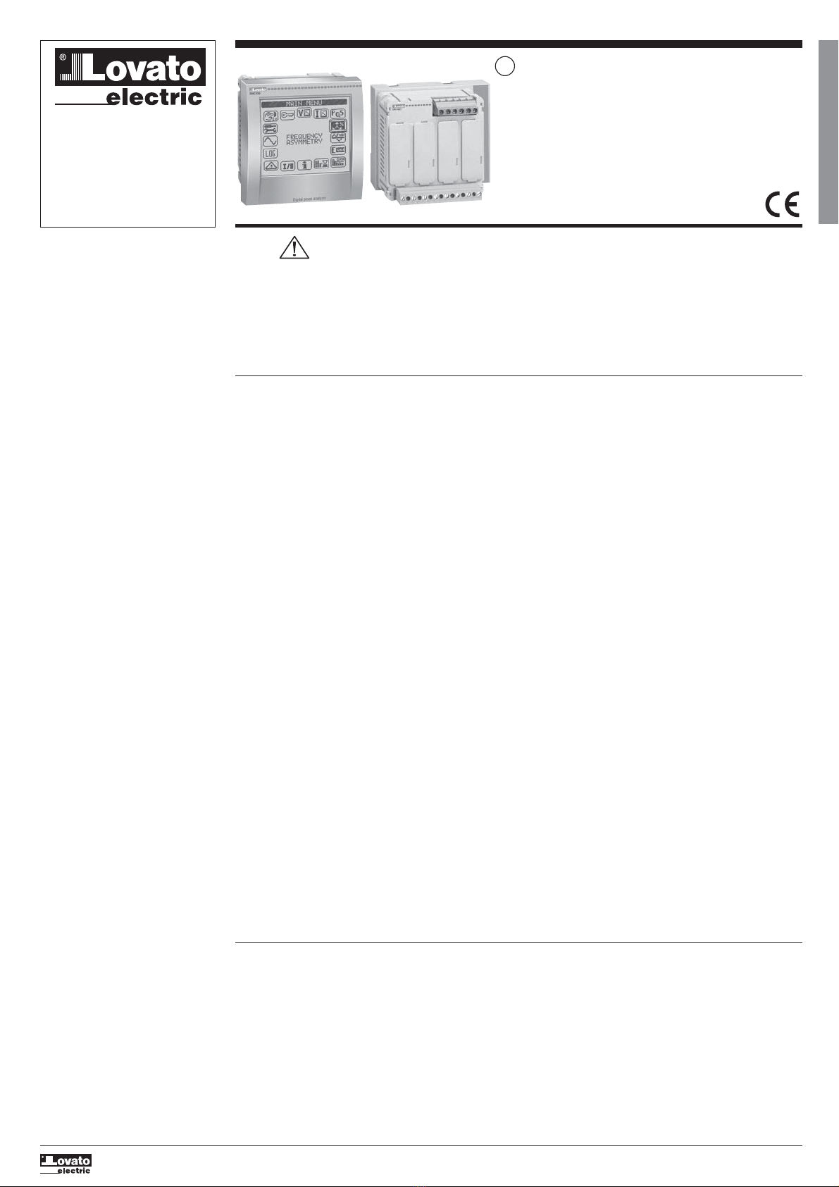
DMG900 - DMG900T
Digital power analyzer - Power transducer
Instructions manual
GB
WARNING!
– Carefully read the manual before the installation or use.
– This equipment is to be installed by qualified personnel, complying with current standards, to avoid damages or safety hazards.
– Before any maintenance operation on the device, remove all the voltages from supply and measuring inputs and short-circuit the CT input terminals.
– The manufacturer cannot be held responsible for electrical safety in case of improper use of the equipment.
– Products illustrated herein are subject to alteration and changes without prior notice. Technical data and descriptions in the documentation are accurate, to
the best of our knowledge, but no liabilities for errors, omissions or contingencies arising therefrom are accepted.
– A circuit breaker must be included in the electrical installation of the building. It must be installed close by the equipment and within easy reach of the
operator. It must be marked as the disconnecting device of the equipment: IEC /EN 61010-1 § 6.11.2.
– Clean the instrument with a soft dry cloth; do not use abrasives, liquid detergents or solvents.
INDEX Page
Introduction . . . . . . . . . . . . . . . . . . . . . . . . . . . . . . . . . . . . . . . . . . . . . . . . . . . . . . . . . . . . . . . . . . . . . . . . . . . . . . . . . . . . . . . . . . . . . . . . . . . . . . . . . . . . . . . . . 1
Description . . . . . . . . . . . . . . . . . . . . . . . . . . . . . . . . . . . . . . . . . . . . . . . . . . . . . . . . . . . . . . . . . . . . . . . . . . . . . . . . . . . . . . . . . . . . . . . . . . . . . . . . . . . . . . . . . 2
Touch screen functions . . . . . . . . . . . . . . . . . . . . . . . . . . . . . . . . . . . . . . . . . . . . . . . . . . . . . . . . . . . . . . . . . . . . . . . . . . . . . . . . . . . . . . . . . . . . . . . . . . . . . . . . 2
Neutral measurement . . . . . . . . . . . . . . . . . . . . . . . . . . . . . . . . . . . . . . . . . . . . . . . . . . . . . . . . . . . . . . . . . . . . . . . . . . . . . . . . . . . . . . . . . . . . . . . . . . . . . . . . . 2
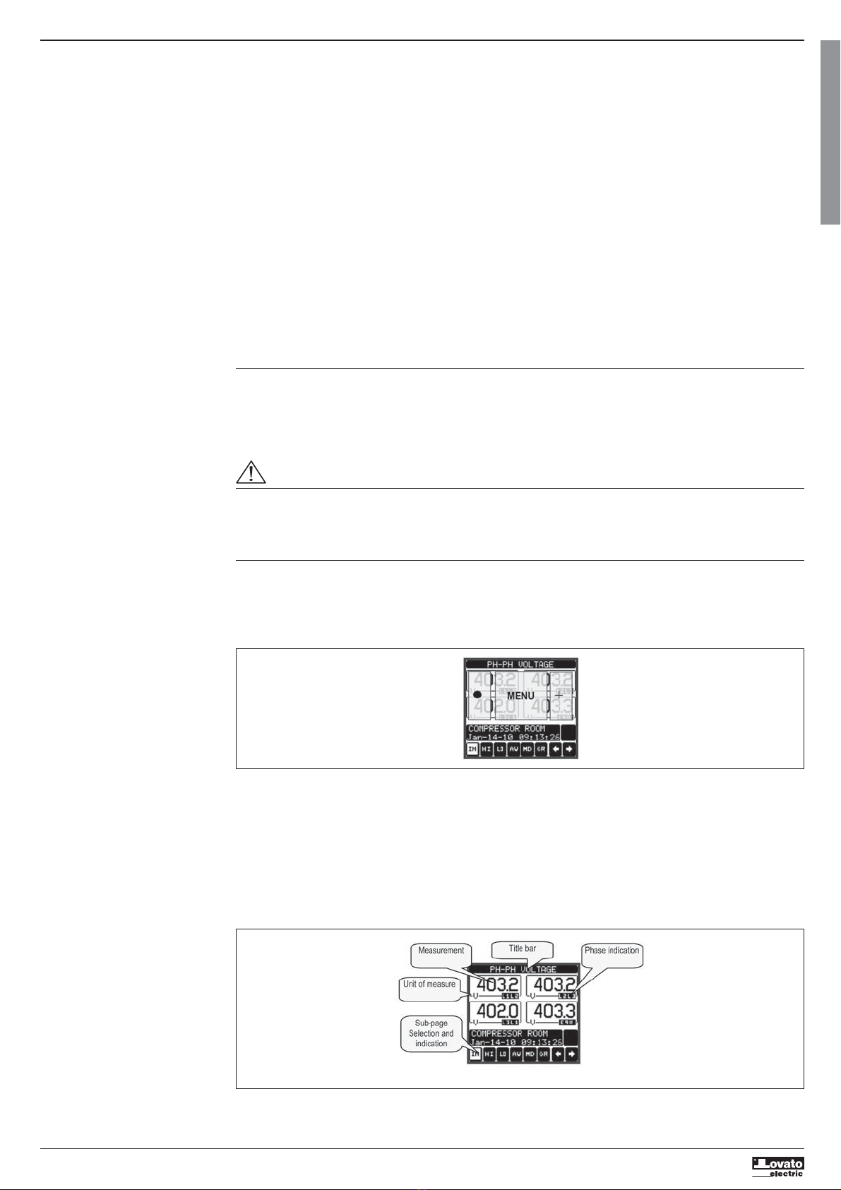
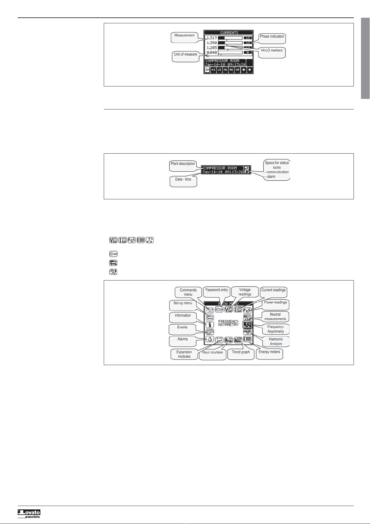
Measurement viewing . . . . . . . . . . . . . . . . . . . . . . . . . . . . . . . . . . . . . . . . . . . . . . . . . . . . . . . . . . . . . . . . . . . . . . . . . . . . . . . . . . . . . . . . . . . . . . . . . . . . . . . . . 2
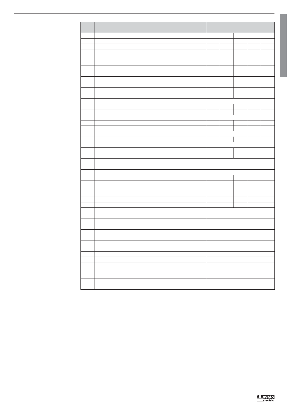
Main menu . . . . . . . . . . . . . . . . . . . . . . . . . . . . . . . . . . . . . . . . . . . . . . . . . . . . . . . . . . . . . . . . . . . . . . . . . . . . . . . . . . . . . . . . . . . . . . . . . . . . . . . . . . . . . . . . . 3
Table of display pages . . . . . . . . . . . . . . . . . . . . . . . . . . . . . . . . . . . . . . . . . . . . . . . . . . . . . . . . . . . . . . . . . . . . . . . . . . . . . . . . . . . . . . . . . . . . . . . . . . . . . . . . . 4
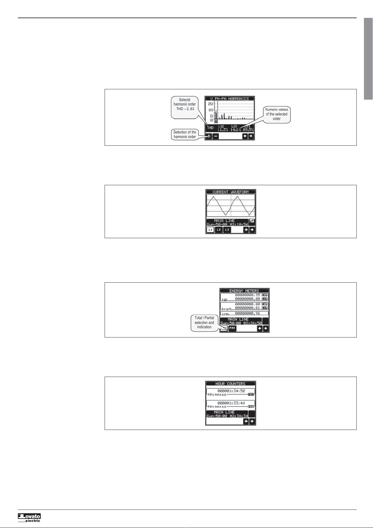
Harmonic analysis page . . . . . . . . . . . . . . . . . . . . . . . . . . . . . . . . . . . . . . . . . . . . . . . . . . . . . . . . . . . . . . . . . . . . . . . . . . . . . . . . . . . . . . . . . . . . . . . . . . . . . . . 5
Waveform page . . . . . . . . . . . . . . . . . . . . . . . . . . . . . . . . . . . . . . . . . . . . . . . . . . . . . . . . . . . . . . . . . . . . . . . . . . . . . . . . . . . . . . . . . . . . . . . . . . . . . . . . . . . . . . 5
Energy meters page . . . . . . . . . . . . . . . . . . . . . . . . . . . . . . . . . . . . . . . . . . . . . . . . . . . . . . . . . . . . . . . . . . . . . . . . . . . . . . . . . . . . . . . . . . . . . . . . . . . . . . . . . . 5
Hour counters page . . . . . . . . . . . . . . . . . . . . . . . . . . . . . . . . . . . . . . . . . . . . . . . . . . . . . . . . . . . . . . . . . . . . . . . . . . . . . . . . . . . . . . . . . . . . . . . . . . . . . . . . . . . 5
Trend graph page . . . . . . . . . . . . . . . . . . . . . . . . . . . . . . . . . . . . . . . . . . . . . . . . . . . . . . . . . . . . . . . . . . . . . . . . . . . . . . . . . . . . . . . . . . . . . . . . . . . . . . . . . . . . 6
Counters page . . . . . . . . . . . . . . . . . . . . . . . . . . . . . . . . . . . . . . . . . . . . . . . . . . . . . . . . . . . . . . . . . . . . . . . . . . . . . . . . . . . . . . . . . . . . . . . . . . . . . . . . . . . . . . . 6
User pages . . . . . . . . . . . . . . . . . . . . . . . . . . . . . . . . . . . . . . . . . . . . . . . . . . . . . . . . . . . . . . . . . . . . . . . . . . . . . . . . . . . . . . . . . . . . . . . . . . . . . . . . . . . . . . . . . 6
Time and date . . . . . . . . . . . . . . . . . . . . . . . . . . . . . . . . . . . . . . . . . . . . . . . . . . . . . . . . . . . . . . . . . . . . . . . . . . . . . . . . . . . . . . . . . . . . . . . . . . . . . . . . . . . . . . . 6
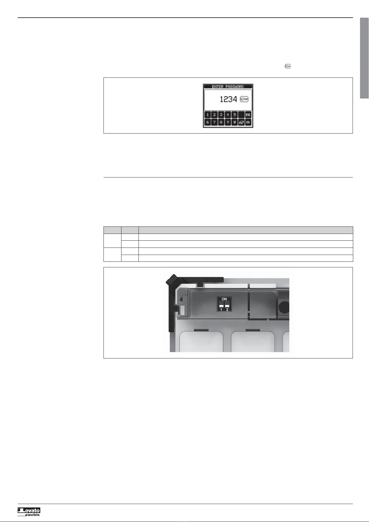
Password access . . . . . . . . . . . . . . . . . . . . . . . . . . . . . . . . . . . . . . . . . . . . . . . . . . . . . . . . . . . . . . . . . . . . . . . . . . . . . . . . . . . . . . . . . . . . . . . . . . . . . . . . . . . . . 7
Settings lock . . . . . . . . . . . . . . . . . . . . . . . . . . . . . . . . . . . . . . . . . . . . . . . . . . . . . . . . . . . . . . . . . . . . . . . . . . . . . . . . . . . . . . . . . . . . . . . . . . . . . . . . . . . . . . . . 7
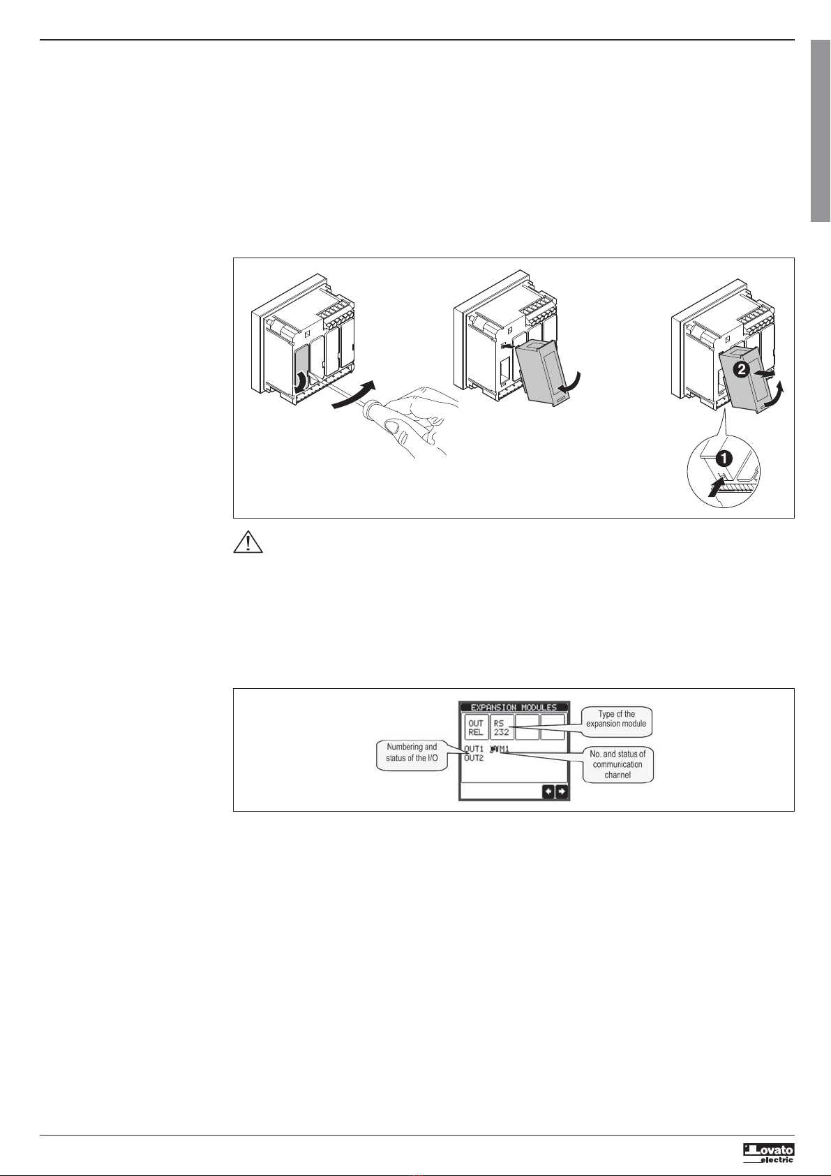
Expandability . . . . . . . . . . . . . . . . . . . . . . . . . . . . . . . . . . . . . . . . . . . . . . . . . . . . . . . . . . . . . . . . . . . . . . . . . . . . . . . . . . . . . . . . . . . . . . . . . . . . . . . . . . . . . . . . 8
Additional resources . . . . . . . . . . . . . . . . . . . . . . . . . . . . . . . . . . . . . . . . . . . . . . . . . . . . . . . . . . . . . . . . . . . . . . . . . . . . . . . . . . . . . . . . . . . . . . . . . . . . . . . . . . 9
Communication channels . . . . . . . . . . . . . . . . . . . . . . . . . . . . . . . . . . . . . . . . . . . . . . . . . . . . . . . . . . . . . . . . . . . . . . . . . . . . . . . . . . . . . . . . . . . . . . . . . . . . . . 9
Inputs, outputs, internal variables, counters . . . . . . . . . . . . . . . . . . . . . . . . . . . . . . . . . . . . . . . . . . . . . . . . . . . . . . . . . . . . . . . . . . . . . . . . . . . . . . . . . . . . . . . . 9
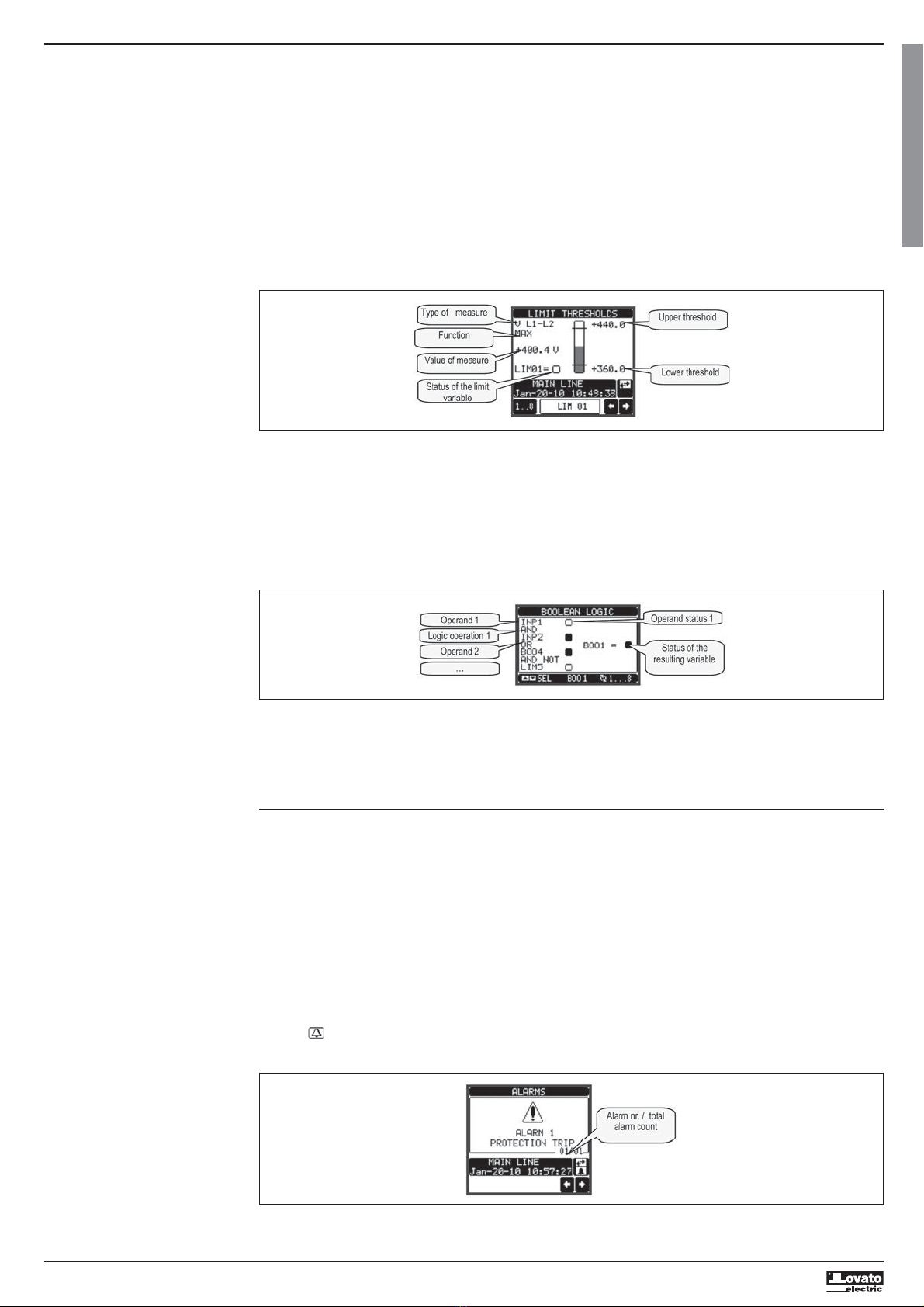
Limit thresholds . . . . . . . . . . . . . . . . . . . . . . . . . . . . . . . . . . . . . . . . . . . . . . . . . . . . . . . . . . . . . . . . . . . . . . . . . . . . . . . . . . . . . . . . . . . . . . . . . . . . . . . . . . . . . 10
Boolean logic . . . . . . . . . . . . . . . . . . . . . . . . . . . . . . . . . . . . . . . . . . . . . . . . . . . . . . . . . . . . . . . . . . . . . . . . . . . . . . . . . . . . . . . . . . . . . . . . . . . . . . . . . . . . . . . . 10
Remote-controlled variables . . . . . . . . . . . . . . . . . . . . . . . . . . . . . . . . . . . . . . . . . . . . . . . . . . . . . . . . . . . . . . . . . . . . . . . . . . . . . . . . . . . . . . . . . . . . . . . . . . . . 10
Alarms . . . . . . . . . . . . . . . . . . . . . . . . . . . . . . . . . . . . . . . . . . . . . . . . . . . . . . . . . . . . . . . . . . . . . . . . . . . . . . . . . . . . . . . . . . . . . . . . . . . . . . . . . . . . . . . . . . . . . 10
Event log . . . . . . . . . . . . . . . . . . . . . . . . . . . . . . . . . . . . . . . . . . . . . . . . . . . . . . . . . . . . . . . . . . . . . . . . . . . . . . . . . . . . . . . . . . . . . . . . . . . . . . . . . . . . . . . . . . . 11
Tariffs . . . . . . . . . . . . . . . . . . . . . . . . . . . . . . . . . . . . . . . . . . . . . . . . . . . . . . . . . . . . . . . . . . . . . . . . . . . . . . . . . . . . . . . . . . . . . . . . . . . . . . . . . . . . . . . . . . . . . 11
Monthly energy counters . . . . . . . . . . . . . . . . . . . . . . . . . . . . . . . . . . . . . . . . . . . . . . . . . . . . . . . . . . . . . . . . . . . . . . . . . . . . . . . . . . . . . . . . . . . . . . . . . . . . . . 12
Data logger function . . . . . . . . . . . . . . . . . . . . . . . . . . . . . . . . . . . . . . . . . . . . . . . . . . . . . . . . . . . . . . . . . . . . . . . . . . . . . . . . . . . . . . . . . . . . . . . . . . . . . . . . . . 12
Energy quality analysis . . . . . . . . . . . . . . . . . . . . . . . . . . . . . . . . . . . . . . . . . . . . . . . . . . . . . . . . . . . . . . . . . . . . . . . . . . . . . . . . . . . . . . . . . . . . . . . . . . . . . . . . 12
Selection of interface type (DMG900T) . . . . . . . . . . . . . . . . . . . . . . . . . . . . . . . . . . . . . . . . . . . . . . . . . . . . . . . . . . . . . . . . . . . . . . . . . . . . . . . . . . . . . . . . . . . . 13
Setting of parameters (set-up) . . . . . . . . . . . . . . . . . . . . . . . . . . . . . . . . . . . . . . . . . . . . . . . . . . . . . . . . . . . . . . . . . . . . . . . . . . . . . . . . . . . . . . . . . . . . . . . . . . 14
Table of parameters . . . . . . . . . . . . . . . . . . . . . . . . . . . . . . . . . . . . . . . . . . . . . . . . . . . . . . . . . . . . . . . . . . . . . . . . . . . . . . . . . . . . . . . . . . . . . . . . . . . . . . . . . . . 15
Commands menu . . . . . . . . . . . . . . . . . . . . . . . . . . . . . . . . . . . . . . . . . . . . . . . . . . . . . . . . . . . . . . . . . . . . . . . . . . . . . . . . . . . . . . . . . . . . . . . . . . . . . . . . . . . . 21
Wiring test . . . . . . . . . . . . . . . . . . . . . . . . . . . . . . . . . . . . . . . . . . . . . . . . . . . . . . . . . . . . . . . . . . . . . . . . . . . . . . . . . . . . . . . . . . . . . . . . . . . . . . . . . . . . . . . . . . 21
Technical characteristics . . . . . . . . . . . . . . . . . . . . . . . . . . . . . . . . . . . . . . . . . . . . . . . . . . . . . . . . . . . . . . . . . . . . . . . . . . . . . . . . . . . . . . . . . . . . . . . . . . . . . . . 22
Installation . . . . . . . . . . . . . . . . . . . . . . . . . . . . . . . . . . . . . . . . . . . . . . . . . . . . . . . . . . . . . . . . . . . . . . . . . . . . . . . . . . . . . . . . . . . . . . . . . . . . . . . . . . . . . . . . . . 23
Wiring diagrams . . . . . . . . . . . . . . . . . . . . . . . . . . . . . . . . . . . . . . . . . . . . . . . . . . . . . . . . . . . . . . . . . . . . . . . . . . . . . . . . . . . . . . . . . . . . . . . . . . . . . . . . . . . . . 24
Terminal arrangement . . . . . . . . . . . . . . . . . . . . . . . . . . . . . . . . . . . . . . . . . . . . . . . . . . . . . . . . . . . . . . . . . . . . . . . . . . . . . . . . . . . . . . . . . . . . . . . . . . . . . . . . . 25
Mechanical dimensions . . . . . . . . . . . . . . . . . . . . . . . . . . . . . . . . . . . . . . . . . . . . . . . . . . . . . . . . . . . . . . . . . . . . . . . . . . . . . . . . . . . . . . . . . . . . . . . . . . . . . . . . 25
INTRODUCTION
DMG900 - The DMG900 power analyzer has been designed to combine the maximum possible easiness of operation together with a wide choice of advanced
functions. Thanks to its flush-mount 96x96mm housing, the DMG900 joins the modern design of the front panel with the tool-less mounting of the device body
and the expansion capability of the rear panel, where it is possible to mount plug-in modules of EXP… series. The graphic, touch-screen LCD display offers a
user-friendly interface. The rich variety of functions, makes the DMG series multimeters the ideal choice for a wide range of applications.
DMG900T - The DMG900T is the Transducer version of the DMG900, for DIN-rail mount. This device has the same characteristics as the DMG900, but has no
display and touch screen. Instead of the integrated display, the DMG900T has an interface board that consent the connection in one of the following modes:
– RS232 communication port
– RS485 communication port
– Remote display communication port for DMG900RD
NOTE: When not differently specified, all the characteristics reported in the following part of the manual are referred to both models. In particular, every detail
that is in relation with the display and the touch screen can be referred to the DMG900T used in combination with the remote display unit DMG900RD.

I273 GB I 04 14 31100126
G
B
2
DESCRIPTION
DMG900:
– Flush-mount housing, 96x96mm
– Graphic LCD display, 128x112 pixels, white backlight, 4 grey levels.
– Navigation and setting through touch screen.
– Built-in buzzer.
DMG900T:
– Power transducer
– Version for panel interior, DIN-rail mount
– Selectable interface: RS232 or RS485 or Remote display
Common characteristics:
– Compatible with LV, MV, HV applications.
– 4 voltage measurement channels.
– 4 current measurement inputs, galvanically insulated.
– Texts for measures, set-up and messages in 5 languages.
– Reading of more than 500 electrical parameters.
– Harmonic analysis of voltage and current up to 63.rd order.
– Events storage and management.
– Measure of Power factor (TPF) and Cos-phi (DPF).
– Expansion bus for maximum 4 plug-in modules EXP… series.
– Advanced programmable I/O functions.
– True RMS measurements.
– Continuous (gapless) sampling.
– High accuracy.
– Sealable terminal covers.
– Settings lock through sealable dip-switch.
TOUCH-SCREEN FUNCTIONS
– Thanks to the touch screen display, the user can access very quickly to all measurements and settings.
– Simply touching the various graphic icons that are presented in the various display pages, it is possible to achieve a great operating flexibility.
– To select one function, simply touch the correspondent icon.
– If the function requires a confirmation, click it a second time after it has been selected or confirm by pressing key OK.
– At every activation of the touch panel, a beep is emitted by the buzzer (beep can be disabled through parameter).
WARNING!
– Do not operate the touch screen if has been seriously damaged by an impact.
NEUTRAL MASUREMENT
– The fourth voltage input channel (V4) allows to measure the voltage between neutral and ground.
– The fourth current input channel (I4) is used to measure the current on the neutral line.
– If the CT for the neutral wire is not available, the I4 input can be disabled and the measure will be calculated from the phase currents.
– The dedicated display page shows Neutral-earth voltage, neutral current and THD of neutral current.
VIEWING OF MEASUREMENTS
– The ⬅and ➡icons at the bottom right, allow to scroll the pages one by one. The page being viewed is written in the title bar.
– To scroll the measure pages one by one it is also possible to press the touch screen near the right border (page forward) or near the left border (page
backward).
– Touching the center part of the display recalls the main menu, with the shortcut icons that allow jumping quickly to the desired page. See the Main menu
chapter in the following pages.
– Some of the readings may not be shown, depending on the programming and the wiring of the device (for instance, if programmed-wired for a three-phase
without neutral system, L-N voltage page is not shown).
– For every page, it is possible to access several sub-pages (for instance to show the highest/lowest peak for the selected readings) simply touching the
correspondent icon.
– The sub-page viewed is indicated in by the highlighted icon in the bottom-left part of the display:
•IN = Instantaneous value – Actual instantaneous value of the reading, shown by default every time the page is changed.
•HI = Highest peak – Highest peak of the instantaneous value of the relative reading. The HIGH values are stored and kept even when auxiliary power is
removed. They can be cleared using the dedicated command (see commands menu).
•LO = Lowest peak – Lowest value of the reading, stored from the time the DMG powered-on. It is reseted using the same command used for HI values.
•AV = Average value – Time-integrated value of the reading. Allows showing measurements with slow variations. See integration menu in set-up chapter.
•MD = Maximum Demand – Maximum peak of the integrated value. Stored in non-volatile memory and it is resettable with dedicated command.
•GR = Graphic bars – Shows the measurements with graphic bars.
Example of display page with numeric indication

I273 GB I 04 14 31100126
G
B
3
Example of display page with bar-graphs
Example of auxiliary window
– The user can define to which page and sub-page the display must return to after a period of time has elapsed without any keystroke.
– If needed, it is possible to set the multimeter so that the display will remain always in the position in which it has been left.
– To set these functions see menu M02 – Utility.
AUXILIARY WINDOW
– In each measurement page, there is a part of the display composed by two rows, that the user can use to show auxiliary information, selecting among:
• Alphanumeric description of the plant, the distribution panel or section monitored by the DMG900.
• Current time and date
• Other measurements (energy meters etc.)
– The user can choose the information to be shown on the auxiliary page using the M02 Utility menu.
– By default the auxiliary page shows the palnt description and the time/date.
MAIN MENU
– The main menu is made up of a group of graphic icons (shortcuts) that allow rapid access to measurements and settings.
– Starting from normal viewing, touch the central part of the display. The main menu screen is displayed.
– Touch the icon that represents the required function. The selected icon is highlighted and the central part of the display shows the description of the function.
– To activate the function, press in the central part of the display (on the description) or touch again (double-click) the icon that has already been selected.
– If some of the functions are not available, the correspondent icon will be disabled, that is shown in a light grey colour.
– etc. - Shortcuts that allow jumping to the first page of that group. Starting from that page it is still possible to move
forward-backward in the usual way.
– - Open the password entry page, where it is possible to specify the numeric codes that unlock protected functions (parameter setting, commands menu).
– - Access point to the set-up menu for parameter programming.
– - Access point to the commands menu, where the authorised user can execute some clearing-restoring actions.

I273 GB I 04 14 31100126
G
B
4
TABLE OF DISPLAY PAGES
Selection with
⬅
and ➡Selection with icons
N° PAGES SUB-PAGES
1 VOLTAGE - CURRENT - V(L1-L2), V(L2-L3), V(L3-L1), I(L1), I(L2), I(L3) HI LO AV
2 PHASE-TO-PHASE VOLTAGES - V(L1-L2), V(L2-L3), V(L3-L1), V(LL)EQV HI LO AV GR
3 PHASE-TO-NEUTRAL VOLTAGES - V(L1-N), V(L2-N), V(L3-N), V(L-N)EQV HI LO AV GR
4 PHASE AND NEUTRAL CURRENTS - I(L1), I(L2), I(L3), I(N) calculated HI LO AV MD GR
5 ACTIVE POWER - P(L1), P(L2), P(L3), P(TOT) HI LO AV MD GR
6 REACTIVE POWER - Q(L1), Q(L2), Q(L3), Q(TOT) HI LO AV MD GR
7 APPARENT POWER - S(L1), S(L2), S(L3), S(TOT) HI LO AV MD GR
8 POWER FACTOR - PF(L1),PF(L2),PF(L3),PF(EQ) HI LO AV GR
9 COS-PHI - COS-PHI(L1), COS-PHI(L2), COS-PHI(L3) HI LO AV GR
10 NEUTRAL - V(N-GND), I(N), THD-I (N) HI LO AV GR
11 FREQUENCY-ASYMMETRY - F, ASY(VLL), ASY(VLN), ASY(I) HI LO AV
12 PH-PH VOLTAGE HARMONIC DISTORTION - THD-V(L1-L2), THD-V(L2-L3), THD-V(L3-L1) HI LO AV GR
13 PH-PH VOLTAGE HARMONIC ANALYSIS - H2…63 V(L1-L2)-V(L2-L3)-V(L3-L1)
14 PH-PH VOLTAGE WAVEFORMS L1-L2 L2-L3 L3-L1
15 PH-N VOLTAGE HARMONIC DISTORTION - THD-V(L1),THD-V(L2),THD-V(L3) HI LO AV GR
16 PH-N VOLTAGE HARMONIC ANALYSIS - H2…63 V(L1)-V(L2)-V(L3)
17 PH-N VOLTAGE WAVEFORMS L1-N L2-N L3-N
18 CURRENT HARMONIC DISTORTION - THD-I(L1), THD-I(L2) THD-I(L3) HI LO AV GR
19 CURRENT HARMONIC ANALYSIS - H2…63 I(L1)-I(L2)-I(L3)
20 CURRENT WAVEFORMS L1 L2 L3 N
21 ENERGY METERS - kWh+(TOT), kWh-(TOT), kvarh+(TOT), kvarh-(TOT), kVA(TOT) PARTIAL
22 ENERGY TARIFFS TAR1 … TAR8
23 MONTHLY ENERGY CONSUMPTION JAN … DEC
24 TREND GRAPH
25 HOUR COUNTER - Hr(TOT), Hr(Partial)
26 EXPANSION MODULES
27 COUNTERS CNT1 … CNT4
28 ANALOG INPUTS AIN1 … AIN8
29 ANALOG OUTPUTS AOU1 … AOU8
30 LIMIT THRESHOLDS LIM1 … LIM16
31 BOOLEAN LOGIC BOO1 … BOO8
32 ALARMS ALA1 … ALA16
33 EVENTS EVNT1…100
34 DATA LOGGER
35 WEEKLY ENERGY QUALITY WEEKS 1..52 / LAST
36 MONTHLY ENERGY QUALITY
37 YEARLY ENERGY QUALITY
38 ENERGY QUALITY COUNTERS
39 ENERGY QUALITY WAVEFORM CAPTURE WAVE 1..10
40 TIME AND DATE
41 DC SUPPLY VOLTAGE (only D048 version)
42 INFO-REVISION-SERIAL NO.. MODEL, REV SW, REV HW, SER. No.
43 LOGO
USER-DEFINED PAGE 1
USER-DEFINED PAGE 2
USER-DEFINED PAGE 3
USER-DEFINED PAGE 4
NOTE: Some of the pages listed above may not be available if the function that they must view is not enabled. For instance, if no alarms have been defined, then
the Alarm page will not be shown.
GND = Ground/Earth

I273 GB I 04 14 31100126
G
B
5
HARMONIC ANALYSIS PAGE
– The DMG900 provides the harmonic analysis up to the 63rd order (7th order if frequency = 400Hz) of the following measurements:
• phase-to-phase voltages
• phase-to-neutral voltages
• phase and neutral currents
– For each of these measurements, there is a display page that graphically represents the harmonic content (spectrum) through a bar graph.
– Every column is related to one harmonic order, even and odd. The first column shows the total harmonic distortion (THD).
– Every histogram bar is then divided into three parts, one each phase L1,L2, L3.
– The value of the harmonic content is expressed as a percentage with respect to the fundamental (system frequency).
– It is possible to show the harmonic content in numeric format, selecting the required order through + -. The lower part of the screen will display a little arrow
that points to the selected column, and the relative percentage value of the three phases.
– The vertical scale of the graph is automatically selected among four full-scale values, depending on the column with the highest value.
WAVEFORM PAGE
– This page graphically views the waveform of the voltage and current signals read by the DMG900.
– It is possible to see one phase at a time, selecting it by clicking on the icon with the desired phase.
– The vertical scale (amplitude) is automatically scaled in order to fit the waveform on the screen in the best possible way.
– The horizontal axis (time) shows two consecutive periods referred to the fundamental frequency.
– The graph is automatically updated about every 1s.
ENERGY METERS PAGE
– The Energy meters page shows the following meters simultaneously:
• active energy, Imported and exported
• reactive energy, imported and exported (inductive / capacitive)
• apparent energy.
– The main page shows the total meters. Clicking on the dedicated icons, the display moves to sub-page with partial meters (clearable by the user).
– To clear energy meters, it is necessary to access the commands menu.
HOUR COUNTERS PAGE
– The Hour counters page shows the following meters simultaneously:
• total hour meter (counts the power-on time of the device)
• partial hour meter (counts how long a programmable condition has been true)
– To clear hour counters, it is necessary to access the Commands menu.
– The hour counter page can be completely hidden if the general hour counter enable has been set to OFF (see Hour counter menu).

I273 GB I 04 14 31100126
G
B
6
TREND GRAPH PAGE
– The trend graph page allows to show the changes in the time domain of one measurement selectable among the following:
• average equivalent voltage
• average total active power
• average total reactive power
• average total apparent power.
– The default measurement is the Average total active power. To change the measurement, enter the dedicated menu parameter in the Trend sub-menu.
– It is possible to see, on the graph, the history of the last 96 values of the integrated measurement, each correspondent to a integration time interval.
– The default time interval is equal to 15 minutes, so the graph depth in time is equal to 24h.
– With the default factory setting, the trend graph shows the active power demand variation of the last day.
– The consumption data is lost when auxiliary power is removed from the DMG device or when the settings in the set-up menu are changed.
– When the maximum storing capacity is exceeded, the newest data will overwrites the oldest, so that the most recent data is always shown.
– The vertical full-scale is calculated automatically, depending on the measurement selected and the highest value recorded in the Set-up menu.
COUNTERS PAGE
– The counters page displays CNT1…4 counters.
– It is possible to count the number of times an input is activated, or a limit has been overcame etc. The count condition is defined by Counter source
parameters.
– For every counter, it is possible to define a description and a unit of measure with a free text, for instance litres, kg, etc.
– It is possible to define a conversion factor between the number of pulse counts and the measurement shown on display. This function can be obtained by
specifying a multiply and a divide factor. For instance, setting the multiplier k to 3, for every pulse count, the value shown will be incremented 3 times. If
instead, a divider is set to 10, then the value will be incremented by one only after 10 pulses have been applied to the input. With a combination of multiply
and divide factor, any ratio between counts and measurement can be achieved.
– If the counter has no divide factor, the screen will indicate the counter without fractional digits, otherwise the counter will be displayed with two decimal
digits.
– The counters can be cleared by means of commands menu or by means of the Reset source signal, defined by dedicated parameters.
USER PAGES
– The user can create a maximum of 4 customised display pages.
– Each of these pages can view 4 measurements, freely chosen among the available readings of the DMG900.
– The title of the page can be freely programmed by the user, allowing, for instance, indicating the part of the plant supervised by the multimeter.
– The user pages are placed in a position that allows to reach them easily starting from the first page, by pressing button
⬅
.
– Like all other pages, it is possible to set the multimeter to return automatically to the user page after a time has elapsed without touch screen activation.
– To define the user page, see the dedicated menu M15 in the parameter set-up chapter.
TIME AND DATE
– The DMG900 manages the time and date, that is used for the storage of events and for time-related functions.
– If the DMG900 is equipped with an expansion module with RTC (real-time clock), then the time and date are kept updated even without auxiliary power
supply, for a maximum of about 2 weeks.
– If instead no EXP module with RTC is available , then the DMG900 operates with a virtual RTC that does not update when the auxiliary power is off.
– In this case, a dedicated parameter allows to move automatically to the time-date setting page every time the device has been powered off and on, in order to
remind the user to verify 7 set the correct time and date.
– The time and date can be displayed:
• On the auxiliary window, that is shown together with mosto f the measure pages.
• On the dedicated page, where it is possible to set the current time/date.

I273 GB I 04 14 31100126
G
B
7
PASSWORD ACCESS
– The password is used to enable or lock the access to setting menu (set-up) and to commands menu.
– For brand-new devices (factory default), the password management is disabled and the access is free. If instead the passwords have been enabled and
defined, then to get access, it is necessary to enter the password first, specifying the numeric code through the keypad.
– To enable password management and to define numeric codes, see set-up menu.
– There are two access levels, depending on the code entered:
–User-Level access – Allows clearing of recorded values but not editing of set-up parameters.
–Advanced access level – Same rights of the user access plus settings editing-restoring.
– From normal viewing, recall main menu by touching the central part of the display, then select the password icon and press OK.
– The display shows the screen in picture:
– Enter numeric code, then press OK.
– If the password code entered matches the User access code or the Advanced access code, then the correspondent unlock message is shown.
– Once unlocked the password, the access rights last until:
• the device is powered off.
• the device is reset (after quitting the set-up menu).
• the timeout period of two minutes elapses without any keystroke.
– To quit the password entry screen press ESC key.
SETTINGS LOCK
– On the DMG900 there are two DIP-switches that are used to lock the access to parameter settings and / or to reset operations (commands menu).
– This DIP switches are placed in a way that they become inaccessible once the sealable terminal cover is mounted.
– To change switch position:
• Remove power supply to DMG900 and remove terminal covers (if mounted) and the 8-pole terminal block
• Using a small flat screwdriver, move the switches in the desired position.
• Re-assemble terminal blocks and terminal covers.
– The multimeter is supplied with the switches in unlocked position.
SW POS DESCRIPTION
SW1 ON Parameter settings locked
OFF Parameter settings allowed
SW2 ON Commands menu access locked
OFF Commands menu access allowed

I273 GB I 04 14 31100126
G
B
8
EXPANDABILITY
– Thanks to expansion bus, the DMG900 can be expanded with EXP… series modules.
– It is possible to connect a maximum of 4 EXP… modules.
– The supported EXP modules can be grouped in the following categories:
• communication modules
• digital I/O modules
• analog I/O modules
• memory modules
– To insert an expansion module:
• remove the power supply to DMG900
• remove the terminal cover and the 8-pole terminal block
• remove the protecting cover of one of the expansion slots
• insert the upper hook of the module into the fixing hole
• rotate down the module body, inserting the connector on the bus
• push until the bottom clip snaps into its housing
• Re-install the terminal block and the transparent terminal cover
– The modules insertion sequence is free.
WARNING!
– When the EXP.. module is installed on a DMG series multimeter, it is mandatory to install the sealable terminal block covers supplied with the
multimeter.
– When a DMG900 is powered on, it automatically recognises the EXP modules that have been mounted.
– For the DMG900T, when it is not connected to a remote display DMG900RD, to recognize the expansion modules it is necessary to put the DIP switches in
the correct position (see details on page 19).
– If the system configuration has changed with respect to the last saved, (one module has been added or removed), the base unit asks the user to confirm the
new configuration. In case of confirmation, the new configuration will be saved and will become effective, otherwise the mismatch will be shown at every
subsequent power-on of the multimeter.
– The actual system configuration is shown in the dedicated page of the display (expansion modules), where it is possible to see the number, the type and the
status of the modules.
– The I/O numbering is shown under each module.
– The status (energised/de-energised) of every single I/O and communication channel is highlighted in reverse.
CLICK!
1234

I273 GB I 04 14 31100126
G
B
9
ADDITIONAL RESOURCES
– The expansion modules provide additional resources that can be used through the dedicated set-up menus.
– The set-up menus related to the expansions are always accessible, even if the expansion modules are not physically fitted.
– Since it is possible to add more than one module of the same typology (for instance two communication interfaces), the set-up menus are multiple, identified
by a sequential number.
– The following table indicates how many modules of each group can be mounted at the same time.
MODULE TYPE CODE FUNCTION MAX No.
COMMUNICATION EXP 10 10 USB 2
EXP 10 11 RS-232
EXP 10 12 RS-485
EXP 10 13 Ethernet
EXP 10 14 Profibus®DP
DIGITAL I/O EXP 10 00 4 INPUTS 4
EXP 10 01 4 STATIC OUTPUTS 4
EXP 10 02 2 INPUTS + 4
2 ST. OUTPUTS
EXP 10 03 2 RELAYS 4
ANALOG I/O EXP 10 04 2 ANALOG INPUTS 4
EXP 10 05 2 ANALOG OUTPUTS 4
MEMORY EXP 10 30 DATA MEMORY + 1
REAL TIME CLOCK
EXP 10 31 DATA MEMORY, 1
REAL TIME CLOCK,
ENERGY QUALITY
COMMUNICATION CHANNELS
– The DMG900 supports a maximum of 2 communication modules, indicated as COMn. The communication set-up menu M07 is thus divided into two sections
(n=1 and n = 2) of parameters for the setting of the ports.
– The communication channels are completely independent, both for the hardware (physical interface) and for the communication protocol.
– The two channels can communicate at the same time.
– Activating the Gateway function it is possible to use a DMG900 with both an Ethernet port and a RS485 port, that acts as a bridge over other DMGs equipped
with RS-485 only, in order to achieve a more economic configuration (only one Ethernet port).
– In this network, the DMG with two communication ports will be set with both communication channels (COM1 and COM2) with Gateway parameter set to
ON, while the other DMGs will be configured normally with Gateway = OFF.
INPUTS, OUTPUTS, INTERNAL VARIABLES, COUNTERS, ANALOG INPUTS
– The inputs and outputs of the expansion modules are identified by a code and a sequence number. For instance, the digital inputs are identified by code INPx,
where x is the number of the input. In the same way, digital outputs are identified by code OUTx.
– The sequence number of I/Os is simply based on their mounting position, with a progressive numbering from left to right. For instance the input INP1 is the
input terminal closest to the base unit, while the subsequent inputs will be named INP2, INP3 and so on.
– The DMG900 supports a maximum of 16 digital inputs and 16 outputs that will thus be numbered INP1…16 and OUT1…16. For every I/O, there is a
dedicated setting menu that allows specifying functionality and properties.
– In a similar way, there are some internal bit-variables (markers) that can be associated to the outputs or combined between them. For instance, it is possible
to apply some limit thresholds to the measurements done by the multimeter (voltage, current, power, etc.). In this case, an internal variable named LIMx will
be activated when the measurements will go outside the limits defined by the user through the dedicated setting menu.
– Furthermore, there are up to 4 counters (CNT1..CNT4) that can count pulses coming from an external source (through a digital input INPx) or the number of
times that a certain condition as been verified. For instance, defining a limit threshold LIMx as the count source, it will be possible to count how many times
one measurement has exceeded a certain limit.
– Finally it is possible to manage up to 8 analog inputs, connected to external analog sensors (temperature, pressure, flow etc). The value read from the
sensors can be scaled to any unit of measure, visualized on the display and transmitted on the communication bus. The value read from analog inputs is
shown on the dedicated display page. They can be used to drive LIMx limit thresholds.
– The following table groups all the I/O and the internal variables managed by the DMG900.
CODE DESCRIPTION RANGE
INPx Digital inputs 1…16
OUTx Digital outputs 1…16
LIMx Limit thresholds 1…16
BOOx Boolean logic 1…8
REMx Remote-controlled variables 1…8
ALAx Alarms 1…16
PULx Energy count pulses 1…5
CNTx Counters 1…4
AINx Analog inputs 1…8
AOUx Analog outputs 1…8
The status of each I/O or internal variable can be shown on the display in the dedicated page.

I273 GB I 04 14 31100126
G
B
10
LIMIT THRESHOLDS (LIM)
– The LIMn thresholds are internal variables whose status depends on the out-of-limits of one particular measurement set by the user (e.g. total active power
higher than 25kW) among all those measured.
– To make the setting of the thresholds easier, since the limits can span in a very wide range, each of them can be set using a base number and a multiplier
(for example: 25 x 1k = 25000).
– For each LIM, there are two thresholds (upper and lower). The upper threshold must always be set to a value higher than the lower threshold.
– The meaning of the thresholds depends on the following functions:
Min function: the lower threshold defines the trip point, while the upper threshold is for the resetting. The LIM trips when the selected measurement is less
than the Lower threshold for the programmed delay. When the measured value becomes higher than the upper setpoint, after the delay, the LIM status is
reset.
Max function: the upper threshold defines the trip point, while the lower threshold is for the resetting. The LIM trips when the selected measurement is more
than upper threshold for the programmed delay. When the measured value decreases below the lower setpoint, after the delay, the LIM status is reset.
Max+Min function: both thresholds are for tripping. When the measured value is less than lower or more than upper setpoints, then, after the respective
delays, the LIM will trip. When the measured value returns within the limits, the LIM status will be immediately reset.
– Trip denotes either activation or de-activation of the LIM variable, depending on ‘Normal status’ setting.
– If the LIMn latch is enabled, the reset can be done only manually using the dedicated command in the commands menu.
– See set-up menu M08.
BOOLEAN LOGIC (BOO)
– It is possible to create max. 8 internal variables named BOO1..8, whose status depends on the Boolean logic combination of limit thresholds, inputs, outputs,
etc.
– The operands (INP, LIM etc) can be combined between each other with the following Boolean operators: AND, OR, EXOR, AND NOT, OR NOT, EXOR NOT.
– Every Boolean variable is the result of max 4 operands combined with 3 logic operations.
– Example: if one wants the Boolean variable BOO1 to be activated when the limits LIM1, LIM2 and LIM3 are all active or when the input INP1 is active, BOO1
must programmed as the combination of LIM2 AND LIM3 AND LIM4 OR INP1.
– It is not necessary to use all 4 operands for one Boolean variable. If for instance, one wants BOO2 to be active when INP1 or INP2 are active, then it is
possible to program BOO2 settings with the combination INP1 OR INP2, leaving the following logic operations set to --- (no operation).
– The BOOLEAN LOGIC page displays, for every variable BOO1..8, the status of the single operands that are involved in the logic operation and the final result,
that is the status of the selected Boolean variable.
REMOTE-CONTROLLED VARIABLES (REM)
– DMG900 can manage up to 8 remote-controlled variables (REM1…REM8).
– Those are variables which status can be modified by the user through the communication protocol and that can be used in combination with outputs,
Boolean logic, etc.
– Example: using a remote variable (REMx) as a source for an output (OUTx), it will be possible to freely energise or de-energise one relay through the
supervision software. This allows to use the DMG900 relays to drive lighting or similar loads.
– Another possible use of REM variables is to enable/disable other functions remotely, inserting them into a Boolean logic in AND with inputs or outputs.
ALARMS (ALA)
– The user has the possibility to define a maximum of 16 programmable alarms (ALA1…ALA16).
– For each alarm, it is possible to define the source that is the condition that generates the alarm, and the text of the message that must appear on the screen
when this condition is met.
– The condition that generates the alarm can be, for instance, the overcoming of a threshold. In this case, the source will be one of the limit thresholds LIMx.
– If instead, the alarm must be displayed depending on the status of an external digital input, then the source will be an INPx.
– With the same criteria, it is possible to also link complex conditions to an alarm, resulting from the logic combination of inputs, limits, etc. In this case, the
Boolean logic variables BOOx must be used.
– For every alarm, the user can define a free message that will appear on the alarm page.
– It is also possible to define a priority for the alarm. If it is a simple indication, then the priority can be set to low. In this case the icon that follows the
message will be the ‘info’ symbol.
– If instead, the alarm must indicate a more critical situation, then setting its priority to High, the message will be displayed with the ‘Warning’ icon, and when
the alarm becomes active, the display page will move automatically on the Alarm screen.
– When one alarm with high priority is present, it is possible to activate the buzzer with an intermittent sound, for a defined period of time or as long as the
user acknowledges it with the dedicated button on the alarm page.
– When several alarms are active at the same time, they are displayed sequentially, and their total number is shown on the status bar.
– The icon is shown on the auxiliary window when one or more alarms are active.
– To reset one alarm that has been programmed with latch, use the dedicated command in the commands menu.
– For alarm programming and definition, refer to set-up menu M09.

TAR-A TAR-B TAR-C TARIFF
OFF OFF OFF 1
ON OFF OFF 2
OFF ON OFF 3
ON ON OFF 4
OFF OFF ON 5
ON OFF ON 6
OFF ON ON 7
ON ON ON 8
I273 GB I 04 14 31100126
G
B
11
TARIFFS
– For the Energy billing, the DMG900 can manage 8 different tariffs in addition to the total and partial Energy meters.
– The tariff selection is made by external digital inputs, and is thus conditioned by the use of an EXP expansion module provided with digital inputs. To select
among the 4 tariffs, the three input functions TAR-A/B/C must be used. Their binary combination selects the tariff as shown in table:
EVENT LOG
– The DMG900 can store a list of events, that can be useful to the user in order to detect anomalies and/or keep track of the plant behaviour.
– Every Eventi s stored with a sequential number and relative time stamp.
– The memory can store the last 100 events, afterwards the oldest events are overwritten by the new ones, with a FIFO logic (circular buffer).
– Events can be grouped into categories, listed in the following table:
– E’ possibile scorrere la memoria eventi visualizzandoli sulla apposita pagina.
– Tramite il pulsante dedicato è poi possibile attivare dei filtri in modo da visualizzare solo un certo tipo di eventi o solo un intervallo temporale.
– If the synchronise input for the power integration is used, then the tariff change becomes active when the sync signal triggers it; otherwise the tariff change
takes place immediately when the status of the selecting inputs changes.
– The tariffs, each with 5 meters (active energy imported/exported, reactive imported/exported, apparent) are shown on a dedicated page, following the total-
partial energy screen.
– If the DMG is equipped with a communication port, then it is possible to select the active tariff through the dedicated command via Modbus protocol (see
technical instruction for Modbus protocol).
EVENT TYPE DESCRIPTION
Power supply Switch ON / OFF
Peaks Update of HI / LO / MD values
Alarms Alarm
Limits Overcoming of user-defined limits
Variables Change of remote-controlled variables
Communication Begin – end of remote control by serial port
Tariffs Change of energy tariff
Setting Access to set-up parameters
Commands Use of command menu to reset etc.
Password Password enter, change of protection DIP-sw
System Change of expansion configuration

I273 GB I 04 14 31100126
G
B
12
DATA LOGGER FUNCTION
– To activate the data logger function the DMG must be equipped with a EXP1030 or EXP1031 memory module.
– To configure the data logger it is necessary to use the PC software DMK-DMG Data logger (code DMKSW10) , that allows to select the variables and
recording modes and to download data in the form of a MS-Access ® database table.
– The data logger allows to store at regular intervals up to 32 variables chosen freely among the multimeter measures.
– For each one of these variables it is possible to store:
1. The instantaneous value that the variable had at the moment of sampling.
2. The average value that the variable had in the sampling period.
3. The maximum value that the variable reached in the sampling period.
4. The minimum value that the variable reached in the sampling period.
– Every record is marked with a time stamp taken from the real-time clock of built in the module. The minimum sampling period (distance between two
records) is of 1 second.
– Considering the amount of memory (8 Mbytes), the number of variables to be stored and the sampling period, the PC software indicates the time that must
elapse before the flash memory is completely filled.
– The recording can be continuous (driven only by regular time intervals) or conditional, driven by the status of one of the internal bit-variables (limits, alarms,
Booleans etc.). In this case it is possible to define which variable controls the starting/stopping of the recording.
– When the memory is full, the user can choose to stop the recording (STOP mode) or to continue overwriting the oldest records (LOOP mode).
– The display page dedicated to the data logger status shows all the fundamental information, like number of measures, available free memory, residual time
before the memory is filled (Note: the last two data are not shown when working in LOOP mode).
– Data recorded by the DMG can be downloaded to the PC disk through a serial interface module.
– For detailed information about the setting of datalogger function see the manual of the DMK-DMG data logger software.
–Note: The memory module mandatory position is slot 1 of the DMG expansion bus (leftmost).
ENERGY QUALITY ANALYSIS
– The DMG900 must be equipped with EXP10 31 expansion module to enable the energy quality function.
– Refer to the relative menu M18 in the parameters setting chapter for the energy quality parameters configuration.
– This function permits to control that the voltage and the frequency measured by the analyzer (normally those provided by the power supplier) remain within
the minimum energy quality parameters according to EN 50160 standard prescriptions.
– In particular, the DMG900 coupled with the EXP10 31 module allows to control the following phenomenon, each identified by a reference code:
• Small variations of integrated average voltage (VLO – VHI)
• Large variations of integrated average voltage (NLO – NHI)
• Harmonic distortion of voltage, like THD or single harmonic levels (THD – HAR)
• Phase asymmetry (ASY)
• Small variations of frequency (FLO-FHI)
• Large variations of frequency (NLO-NHI)
• Sudden reduction of voltage (DIPS)
• Sudden increase of voltage (SWELLS)
• Brief supply voltage interruptions (INTERRUPTIONS).
• Long supply voltage interruptions (INTERRUPTIONS).
– The maximum limit thresholds allowed for the above-indicated phenomenon are adjustable, by the user, through menu M18. The factory-default values of
these limits are set to values specified by the EN 50160 standard.
– The detection of each event can be disabled by setting the correspondent threshold to OFF.
– For all the above-listed phenomenon, when an abnormality occurs, an event with time stamp is logged and stored in the retentive memory, in chronological
order. Only the latest 100 events remain stored.
– “Slow” phenomenon, i.e. those based on integrated measurements (VHI-VLO- THD-HAR-ASY-FHI-FLO), are counted according to the time percentages
during which they remained out of programmed limits. The percentages can be viewed using the “LAST WEEKLY” energy quality display page; viewing is
intended to be of last week, of any week of last year, of last month (last 4 weeks) or of the entire last year.
– Instead for “sudden” events (dip, swell, interruption), energy quality counters are increased and indicate the number of times this type of abnormality occurs
as of the last clearing date (see commands menu).
– Dips, swells and interruptions are controlled comparing the RMS value of the voltage and are checked every half cycle of the fundamental frequency (e.g.
every 10ms at 50Hz).
MONTHLY ENERGY COUNTERS
– The DMG900 stores the status of Energy counters of the last 12 months.
– For every month the unit displays the 5 total counters (kwh+, kwh-, kvarh+, kvarh-,kVAh) and the difference with respect to the previous month (monthly
energy consumption).
– The storage of the monthly situation takes place at midnight of the first day of each month.
– Through the dedicated monthly energies page it is possible to browse through the months and to switch between absolute count (TOT = value of the counter
at the end of the month) and relative count (CON = consumption in that month).
– The annual table of monthly energy is update cyclically. It is possible to clear it completely through the dedicated command in the command menu.
– If a count is not available (time period not elapsed yet), then some dashes are shown.

I273 GB I 04 14 31100126
G
B
13
– Ultimately, there are analog counters in addition to those mentioned above, which also record the “slow” phenomenon but with large variations (NHI and
NLO for voltage and frequency). These events should never take place and, for this reason, the N (never) reference is used.
– When the control function of energy quality is enabled, the integration time for voltage is automatically programmed to 10 minutes while for frequency to 10
seconds.
– To be able to use the energy analysis function, the user expressly must program the rated values of voltage and frequency using the relevant parameters
P01.03 and P01.08 in the General menu. By leaving them set to AUT, the energy quality function will not be enabled. The rated voltage is always referred to
the phase-to-phase value.
– It is also important to configure the type of wiring (P01.07), with or without neutral.
– When the distortion control mode is set to single harmonics (HAR) the thresholds, different for each order of harmonic from the 2nd up to 25th, are the ones
defined in the dedicated table in the EN50160 reference standard.
SELECTION OF INTERFACE TYPE (DMG900T)
– The DMG900T is equipped with three interface ports that can be used alternatively (it is not possible to connect more than one interface at a time).
– The selection of the active ports done through a couple of DIP-switches, according to the following table:
SW1 SW2 DESCRIPTION
OFF OFF Remote display DMG900RD
ON OFF RS-485 (COM1)
OFF ON RS-232 (COM1)
ON ON Enables automatic recognition of Expansion modules
– It is recommended to change interface selection only when the unit is not powered. If the interface selection is changed while the unit is powered, the system
will execute a system reset.
ATTENTION!
– The RS-232, RS-485 and remote display port are not insulated among them.
– Connect only one interface at a time.
Weekly Energy quality page
Energy quality Counters page
Waveform Capture page

I273 GB I 04 14 31100126
G
B
14
– The following table lists the available sub-menus:
Cod. MENU DESCRIPTION
M01 GENERAL Detailed data of the installation
M02 UTILITY Language, backlight, display pages, etc.
M03 PASSWORD Access codes enabling
M04 INTEGRATION Readings integration time
M05 HOUR COUNTER Hour counter enabling
M06 TREND GRAPH Trend graph reading and scale
M07 COMMUNICATION (COMn) Communication ports parameters (DMG210)
M08 LIMIT THRESHOLDS (LIMn) Limit thresholds on readings
M09 ALARMS (ALAn) Alarm messages
M10 COUNTERS (CNTn) General counters
M11 ENERGY PULSING (PULn) Energy pulse count
M12 BOOLEAN LOGIC (BOOn) Boolean logic variables
M13 INPUTS (INPn) Digital inputs
M14 OUTPUTS (OUTn) Digital outputs
M15 USER PAGES (PAGn) User-defined pages
M16 ANALOG INPUTS (AINn) Analog inputs
M17 ANALOG OUTPUTS (AOUn) Analog outputs
M18 ENERGY QUALITY Energy quality analysis
– Select the sub-menu and press OK to show the parameters.
– Each parameter is shown with code, description and present value.
– When selecting the Remote Display position, the DMG900T is preset to control the DMG900RD, connected by a dedicated cable with RJ45 8-pole plugs.
– When the RS-232 or RS-485 port are selected, the transmission format, the protocol and other properties of the communication channel can be selected
from the communication menu COM1 (see set-up programming chapter).
– In these two positions, the DMG900T work as a Transducer, that is it supplies the measurements through the serial port, without a local visualization. This
configuration is used in combination with a remote supervision.
– For details about the communication protocol (format and addresses of the registers holding the measures) please see the Modbus protocol manual for
DMG series.
– In case the DMG900T is used without display, the parameter set-up will have to be done through one of the two interfaces and using the DMKSW software.
– The Module recognition position has to be used when some EXP expansion modules are plugged in the DMG900T. The modules need to be recognized by the
base unit. If the system is equipped with a remote display, then the recognition can be carried out using the usual page on the display. Otherwise, moving the
DIP-switches in this position, the new module configuration will be stored. This operation is shown by a 1-sec flash of the red DATA LED. After modules have
been recognized, the DIP-switches can be positioned back to the desired interface selection.
PARAMETER SETTING (SET-UP)
– With normal viewing, press center of display to recall the General menu, then select icon to open the set-up menu screen.
– The display will show the table below, with the parameters grouped in sub-menus with a function-related criteria.
– Select the required menu with
keys and confirm with OK.
– To quit set-up and go back to the readings viewing, press ESC.
Set-up: menu selection
Set-up: parameter selection

I273 GB I 04 14 31100126
G
B
15
– To modify the setting of one parameter, select it and then press OK.
– If the Advanced level access code has not been entered, it will not be possible to enter editing page and an access denied message will be shown.
– If instead the access rights are confirmed, then the editing screen will be shown.
Set-up: editing page
– When the editing screen is displayed, the parameter setting can be modified with + and - keys. The screen shows the new setting, a graphic bar that shows
the setting range, the maximum and minimum values, the previous setting and the factory default.
– Pressing key DEF the setting is set to factory default.
– Press ESC to go back to the parameter selection. The entered value is stored.
– Press ESC again to save all the settings and to quit the set-up menu. The multimeter executes a reset and returns to normal operation.
– If the user does not press the touch screen for more than 2 minutes, the analyzer leaves the set-up automatically and goes back to normal viewing.
PARAMETER TABLE
M01 - GENERAL UoM Default Range
P01.01 CT primary A 5 1-10000
P01.02 CT secondary A 5 1/5
P01.03 Rated voltage V Aut Aut / 50-500000
P01.04 Use VT OFF OFF-ON
P01.05 VT primary V 100 50-500000
P01.06 VT secondary V 100 50-500
P01.07 Wiring L1-L2-L3-N L1-L2-L3-N
L1-L2-L3
L1-L2-L3-N BIL
L1-L2-L3 BIL
L1-N-L2
L1-N
P01.08 Rated frequency Hz Aut Aut-50-60-400
P01.09 CT on neutral (I4 input) ON ON-OFF
P01.01 – CT primary winding rated current.
P01.02 – CT secondary winding rated current.
P01.03 – System rated voltage. Leaving to Aut the multimeters automatically adapts bar-graph full scale.
P01.04 – Set to ON if VT are used. If set to OFF, the following two parameters will be ignored.
P01.05 – VT primary winding rated voltage.
P01.06 – VT secondary winding rated voltage.
P01.07 – Set this parameter according to the used wiring diagram. See witring diagrams on last pages of the manual.
P01.08 – Rated frequency of the line. With Aut setting, the DMG900 selects automatically between 50 and 60 Hz. If an energy quality module EXP10 31 is used
or when working in a 400Hz application, set manually the rated line frequency.

I273 GB I 04 14 31100126
G
B
16
P03.01 – If set to OFF, password management is disabled and the access to setup parameters and command menu is allowed.
P03.02 – When P.03.01 enabled, value to be specified to get user access.
P03.03 – Like P03.02, but referred to Advanced access.
M03 - PASSWORD UoM Default Range
P03.01 Enable passwords OFF OFF-ON
P03.02 User level password 1000 0-9999
P03.03 Advanced level password 2000 0-9999
P04.01 – Selection of average reading calculation method:
Fixed = Readings are integrated for the set time. Every time the integration time elapses, the Average value is updated with the result of the last integration.
Shift = The instantaneous values are integrated for a period f time equal to 1/15th of the set time. Every time this interval elapses, the oldest value is replaced
with the new one just calculated. The average value is updated every 1/15th of the time set, considering a time-sliding window that groups the last 15 calculated
values, with a total length equal to integration time setting.
Sync = Like fixed mode, but the integration intervals are started by an external digital input programmed with Synchronization function.
Bus = Like fixed mode, but the integration intervals are started by communication messages on the serial bus.
P04.02 – Average readings integration time, used for active, reactive and apparent power.
P04.03, P04.04, P04.05 – Readings integration time (AVG) for the correspondent measurements.
M04 - INTEGRATION UoM Default Range
P04.01 Integration mode Shift Fixed / Shift
Sync. / Bus
P04.02 Power integration time min 15 1-60
P04.03 Current integration time min 15 1-60
P04.04 Voltage integration time min 1 1-60
P04.05 Frequency integration time min 1 1-60
M02 - UTILITY UoM Default Range
P02.01 Language English English
Italiano
Francais
Espanol
Portoguese
P02.02 Display contrast % 50 0-100
P02.03 High backlight level % 100 0-100
P02.04 Low backlight level % 30 0-50
P02.05 Low backlight delay sec 30 5-600
P02.06 Default page return sec 60 OFF / 10-600
P02.07 Default page VL-L VL-L / VL-N ...
P02.08 Default sub-page INST INST / HI / LO /
AVG / MD /GRAPH /
1-8
P02.09 Display update time sec 0.5 0.1 - 5.0
P02.10 Plant description DESCR (text – 16 char.)
...
P02.11 Aux window - row 1 DESC DESC-RTC-kWh-
kvarh
P02.12 Aux window - row 2 RTC DESC-RTC-kWh-
kvarh
P02.13 Buzzer sound ON OFF / ON
P02.14 Buzzer activation on alarm OFF OFF / ON
P02.15 Buzzer duration sec 10 1-600 / ON
P02.16 Set clock at power -on ON OFF / ON
P02.06 – If set to OFF the display always remains in the page where the user left it. If set to a time delay, after that time the display page goes back to page set
in P02.07.
P02.07 – Number of the page to which the display returns automatically after time specified by P02.06 has elapsed from the last keystroke.
P02.08 – Sub-page type to which the display returns after P02.06 has elapsed.
P02.10 – Alphanumeric description of the plant or sub-section monitored by DMG900, that can be shown in the auxiliary window.
P02.11 – P02.12 – Define the content of the two rows of the auxiliary window. It is possible to select among plant description, date and hour, energy counters
etc.
P02.13 – Global enable of the beep from the buzzer (touch panel, alarms etc).
P02.14 – Enables the beep from the buzzer when an alarm arises.
P02.15 – Duration of the beep from the buzzer when an alarm arises.
P02.16 – Shows the date-time setting page at power on.
P05.01 – If set to OFF the hour meters are disabled and the hour meter page is not shown.
P05.02 – If set to OFF, the partial hour meter is not incremented. If ON, time is incremented as long as DMG is powered.
P05.03 – Number of the channel (x) of the variable eventually used in the previous parameter. Example: If the partial hour counter must count the time during
which one measurement is above a certain threshold, e.g. defined by LIM3, then it is necessary to program LIM in the previous parameter and channel 3 in this
parameter.
M05 - HOUR COUNTER UoM Default Range
P05.01 Hour counters enable ON OFF-ON
P05.02 Partial hour counter enable ON OFF-ON- INPx-
LIMx-BOOx
P05.03 Channel number (x) 1 1-16

I273 GB I 04 14 31100126
G
B
17
P06.01 – Selects the reading to be shown on trend graph page.
P06.02 – Choice between automatic range or fixed range defined by the user.
P06.03 – Full scale range value. The unit of measure is the one defined by the selected reading.
P06.04 – Full scale value multiplier.
M06 - TREND GRAPH UoM Default Range
P06.01 Trend graph measure kW (tot) VL-L (eq) AVG
AVG kW (tot) AVG
kvar (tot) AVG
kVA (tot) AVG
P06.02 Autorange ON OFF-ON
P06.03 Full scale value 1000 0-1000
P06.04 Full scale multiplier x1 x1 - x1k - x1M
M07 - COMMUNICATION (COMn, n=1..2) UoM Default Range
P07.n.01 Serial node address 01 01-255
P07.n.02 Serial speed bps 9600 1200
2400
4800
9600
19200
38400
57600
115200
P07.n.03 Data format 8 bit - n 8 bit, no parity
8bit, odd
8 bit, even
7 bit, odd
7 bit, even
P07.n.04 Stop bits 1 1-2
P07.n.05 Protocol Modbus RTU Modbus RTU
Modbus ASCII
Modbus TCP
P07.n.06 IP Address 000.000.000.000 000.000.000.000 -
255.255.255.255
P07.n.07 Subnet mask 000.000.000.000 000.000.000.000 -
255.255.255.255
P07.n.08 IP port 1001 0-9999
P07.n.09 Gateway function OFF OFF/ON
P07.n.10 Client / server Server Client / Server
P07.n.11 Remote IP address 000.000.000.000 000.000.000.000 –
255.255.255.255
P07.n.12 Remote IP port 1001 0-9999
P07.n.13 IP gateway address 000.000.000.000 000.000.000.000 –
255.255.255.255
Note: this menu is divided into 2 sections, for comm channels COM1..2
P07.n.01 – Serial address (node number) for the communication protocol.
P07.n.02 – Serial communication speed.
P07.n.03 – Data format. Can be set to 7 bits only for ASCII protocol.
P07.n.04 – Number of stop bits.
P07.n.05 – Communication protocol selection.
P07.n.06, P07.n.07, P07.n.08, P07.n.13 –TCP-IP coordinates for application with Ethernet interface. Not used for other types of interface modules.
P07.n.09 – Enables the gatreway function. See details in Communication channels chapter.
P07.n.10 – Enabling TCP-IP connection. Server = Awaits connection from a remote client. Client = Establishes a connection to the remote server.
P07.n.11, P07.n.12 – Coordinates for the connection to the remote server when P07.n.10 is set to Client.
M08 - LIMIT TRESHOLDS (LIMn, n=1..16) UoM Default Range
P08.n.01 Reference measure OFF OFF- (measures)
P08.n.02 Function Max Max - Min - Min+Max
P08.n.03 Upper threshold 0 -9999 - +9999
P08.n.04 Multiplier x1 /100 - x10k
P08.n.05 Delay sec 0 0.0 - 600.0
P08.n.06 Lower threshold 0 -9999 - +9999
P08.n.07 Multiplier x1 /100 - x10k
P08.n.08 Delay sec 0 0.0 - 600.0
P08.n.09 Normal status OFF OFF-ON
P08.n.10 Latch OFF OFF-ON
Note: this menu is divided into 16 sections, for limit thresholds LIM1..16
P08.n.01 – Defines which measurement of the multimeter must be compared with limits.
P08.n.02 – Function of the limit threshold. It can be:
Max = LIMn active when the measurement is higher than P08.n.03. P08.n.06 is the reset threshold.
Min = LIMn active when the measurement is lower than P08.n.06. P08.n.03 is the reset threshold.
Min+Max = LIMn active when the measurement is higher than P08.n.03 or is lower than P08.n.06.
P08.n.03 e P08.n.04 – Used to-define the upper threshold, that is made of the value set in P08.n.03 multiplied by P08.n.04.
P08.n.05 – Trip delay on upper threshold.
P08.n.06, P08.n.07, P08.n.08 – Like above, referred to lower threshold.
P08.n.09 – Allows to invert the status of the limit LIMn.
P08.n.10 – Defines if the threshold remains latched and thus needs to be reset manually (ON) or if it is reset automatically (OFF).

I273 GB I 04 14 31100126
G
B
18
M09 - ALARMS (ALAn, n=1..16) Default Range
P09.n.01 Alarm source OFF OFF-LIMx-INPx-BOOx
P09.n.02 Channel number (x) 1 1-16
P09.n.03 Latch OFF OFF-ON
P09.n.04 Priority Low Low-High
P09.n.05 Text ALAn (Text - 16 char)
M10 - COUNTERS CNTn (n=1..4) Default Range
P10.n.01 Count source OFF OFF-ON-INPx-LIMx-BOOx
P10.n.02 Channel number (x) 1 1-16
P10.n.03 Multiplier 1 1-1000
P10.n.04 Divider 1 1-1000
P10.n.05 Counter description CNTn (Text - 16 chars)
P10.n.06 Unit of measure Umn (Text - 6 chars)
P10.n.07 Reset source OFF OFF-ON-INPx-LIMx-BOOx
P10.n.08 Channel number (x) 1 1-16
M11 - PULSES PULn (n=1..5) Default Range
P11.n.01 Source measurement kWh+ kWh+,kWh-,kvarh+,kvarh-,kVAh
P11.n.02 Count unit 100 10/100/1k/10k
P11.n.03 Pulse duration 0.1 0.01-1.00
Note: this menu is divided into 16 sections, for alarms ALA1..16
P09.n.01 – Signal that generates the alarm. It can be the overcoming of a limit threshold (LIMx), the activation of an external alarm (INPx), one Boolean logic
condition (BOOx).
P09.n.02 – Channel number (x) referred to the previous parameter.
P09.n.03 – Defines if the alarm remains latched and has to be reset manually (ON) or if it automatically resets (OFF).
P09.n.04 – If the alarm has high priority, when it is activated the display page switches automatically on the alarm page, and the alarm is shown with the
Warning icon. If instead the priority level is set to Low, the page does not change and it is shown with the ‘information’ icon.
P09.n.05 – Free text of the alarm. Max 16 chars.
Note: this menu is divided into 4 sections, for counters CNT1..4
P010.n.01 = Signal that causes the increment of the counter (on rising edge). It can be the power-on of the multimeter (ON), the overcoming of a limit threshold
(LIMx), the activation of an external input (INPx), one logic combination (BOOx).
P010.n.02 = Number of the channel (x) referred to previous parameter.
P010.n.03 = Multiplying factor. The pulse count is multiplied by this coefficient before being displayed.
P010.n.04 = Dividing factor. The pulse count is divided by this coefficient before being displayed. If different from 1, then the counter is displayed with 2
decimal digits.
P010.n.05 = Description of the counter. Free text 16 characters.
P010.n.06 = Unit of measure of the counter. Free text 6 characters.
P010.n.07 = Signal that causes the reset of the counter. As long as this signal is true, the counter remains to value 0.
P010.n.08 = Number of the channel (x) referred to previous parameter.
Note: this menu is divided into 5 sections, for energy count pulses PUL1..5
P11.n.01 = Type of energy to which the pulse is linked to.
P11.n.02 = Quantity of energy for each pulse. (e.g. 10Wh, 100Wh, 1kWh etc.).
P11.n.03 = Pulse duration.
M12 - BOOLEAN LOGIC (BOOn, n=1..8) Default Range
P12.n.01 Operand 1 OFF OFF-LIMx-INPx-OUTx-REMx-BOOx
P12.n.02 Channel number (x) 1 1 - 16
P12.n.03 Logic operator 1 - - - - - - - AND - OR - EXOR - AND NOT -
OR NOT EXOR NOT
P12.n.04 Operand 2 OFF OFF-LIMx-INPx-OUTx-REMx-BOOx
P12.n.05 Channel number (x) 1 1 - 16
P12.n.06 Logic operator 2 - - - - - - - AND - OR - EXOR - AND NOT -
OR NOT EXOR NOT
P12.n.07 Operand 3 OFF OFF-LIMx-INPx-OUTx-REMx-BOOx
P12.n.08 Channel number (x) 1 1 - 16
P12.n.09 Logic operator 3 - - - - - - - AND - OR - EXOR - AND NOT -
OR NOT EXOR NOT
P12.n.10 Operand 4 OFF OFF-LIMx-INPx-OUTx-REMx-BOOx
P12.n.11 Channel number (x) 1 1 - 16
Note: this menu is divided into 8 sections, for Boolean variables BOO1..8
P12.n.01 = First operand of the Boolean logic.
P12.n.02 = Number of the channel (x) referred to previous parameter.
P12.n.03 = Logic operation between first and second operands.
P12.n.04 = Second operand.
From P12.n.05 to P12.n.11 – (see above).

I273 GB I 04 14 31100126
G
B
19
Note: this menu is divided into 16 sections, for digital inputs INP1..16
P13.n.01 = Input function:
OFF – Input disabled
ON – Input enabled, used as a source for counters, Boolean logic, etc.
LOCK – Settings lock. Does not allow access to both levels.
SYNC – Synchronisation for power/energy integration.
TAR-A, TAR-B, TAR-C – Energy tariff selection. See Energy tariffs chapter.
C01…C09 – When this input is activated (edge-triggered), the correspondent command from the command menu is executed.
P13.n.02 = Normal status of the input. Allows inverting the INPn activation logic.
P13.n.03 - P13.n.04 = Delay on activation – deactivation of the input. Allow to filter the input status to avoid bouncing.
Note: this menu is divided into 8 sections, for digital outputs OUT1..8
P14.n.01 = Function of the output:
OFF – Output disabled
ON – Output always enabled
SEQ – Output enabled in case of wrong phase sequence
LIMx – BOOx – ALAx – PULx – REMx – Output linked to the status of the programmed variable. Allows connecting the status of an output to the status of a limit
threshold, a Boolean variable, an alarm, etc.
P14.n.02 = Number of the channel (x) referred to previous parameter.
P14.n.03 = Normal status of the output. Allows reversing the logic of the output function.
Note: this menu is divided into 4 sections, for user pages PAG1..4
P15.n.01 = Enables user page PAGn.
P15.n.02 = Title of the user page. Free text, 16 chars.
P15.n.03, P15.n.04, P15.n.05, P15.n.06 = Measurement that will be shown in the four frames of the user page.
M13 - INPUTS (INPn, n=1..16) UoM Default Range
P13.n.01 Input function OFF OFF – ON – LOCK -SYNC-
TAR–A – TAR-B – TAR-C –
C01…C09
P13.n.02 Normal status OFF OFF-ON
P13.n.03 ON delay sec 0.05 0.00 - 600.00
P13.n.04 OFF delay sec 0.05 0.00 - 600.00
M14 - OUTPUTS (OUTn, n=1..16) UoM Default Range
P14.n.01 Output function OFF OFF-ON-SEQ-LIMx-
BOOx-ALAx-PULx-
REMx
P14.n.02 Channel number (x) 1 1 - 16
P14.n.03 Idle status OFF OFF-ON
M15 - USER-DEFINED PAGES (PAGn, n=1..4) Default Range
P15.n.01 Page enabling OFF OFF - ON
P15.n.02 Title PAGn (Text - 16 char)
P15.n.03 Measurement 1 OFF OFF- (measurements)
P15.n.04 Measurement 2 OFF OFF- (measurements)
P15.n.05 Measurement 3 OFF OFF- (measurements)
P15.n.06 Measurement 4 OFF OFF- (measurements)
M16 - ANALOG INPUTS (AINn, n=1..8) Default Range
P16.n.01 Input type OFF OFF
0..20mA
4….20mA
0…10V
-5V…+5V
PT100
P16.n.02 Start of scale value 0 -9999 - +9999
P16.n.03 Multiplier x1 /100 – x1k
P16.n.04 Full scale value 0 -9999 - +9999
P16.n.05 Multiplier x1 /100 – x1k
P16.n.06 Description AINn (Text – 16 chars)
P16.n.07 Unite of measure UMn (Text – 6 chars)
Note: this menu is divided into 8 sections, for analog inputs AIN1...AIN8
P16.n.01 = Specifies the type of the analog sensor connected to analog input. Depending on the selection, the sensor must be wired to proper terminals.
See expansion module manual.
P16.n.02 and P16.n.03 = Define the value to be displayed when the signal of the sensor is at the minimum, that is at the beginning of the selected range
(0mA, 0V, -5V etc.).
When using PT100 sensors, these parameters define a constant that is added to the temperature measurement, in the unit of measure defined by P16.n.07.
This feature can be used to compensate measurement errors due to cable length.
P16.n.04 and P16.n.05 = Define the value to be displayed when the signal of the sensor is at the maximum, that is full-scale of the selected range (20mA, 10V,
+5V etc.). these parameters are ignored when using PT100 sensors.
P16.n.06 = Description of the measure linked to the analog input. Free text ,16 char.
P16.n.07 = Unit of measure. Free text, 6 characters.
If a PT100 sensor is used and this parameters is equal to °F, then the temperature measurement will be shown in Fahrenheit degrees, otherwise it will be in
Celsius degrees.,

I273 GB I 04 14 31100126
G
B
20
M17 - ANALOG OUTPUTS (AOUn, n=1..8) Default Range
P17.n.01 Output type OFF OFF
0..20mA
4….20mA
0…10V
-5V…+5V
P17.n.02 Reference measure OFF OFF- (measures)
P17.n.03 Start of scale value 0 -9999 - +9999
P17.n.04 Multiplier x1 /100 – x10k
P17.n.05 Full scale value 0 -9999 - +9999
P17.n.06 Multiplier x1 /100 – x10k
M18 – ENERGY QUALITY Uom Default Range
P18.01 Energy quality eneable OFF OFF-ON
P18.02 Avg. voltage threshold NLO %Un 85.0 OFF / 50-100
P18.03 Avg. voltage threshold LO %Un 90.0 OFF / 50-100
P18.04 Avg. voltage threshold HI %Un 110.0 OFF / 100-150
P18.05 Avg. voltage threshold NHI %Un 115.0 OFF / 100-150
P18.06 Harmonic control mode HARM OFF-THD-HARM
P18.07 THD threshold % 8 1-50
P18.08 Asymmetry threshold % 2.0 OFF / 1-50
P18.09 Avg. frequency threshold NLO % 94.0 OFF / 80-100
P18.10 Avg. frequency threshold LO % 99.0 OFF / 80-100
P18.11 Avg. frequency threshold HI % 101.0 OFF / 100-120
P18.12 Avg. frequency threshold NHI % 104.0 OFF / 100-120
P18.13 DIP threshold %Un 90.0 OFF / 5-100
P18.14 SWELl threshold %Un 110.0 OFF / 100-150
P18.15 DIP/SWELL threshold % 2.0 0-10.0
P18.16 Waveform capture on DIP/SWELL OFF OFF-ON
P18.17 INTERRUPTION threshold %Un 5.0 OFF / 0.1-10.0
P18.18 INTERRUPTION hysteresis %Un 1.0 0…10.0
P18.19 Waveform capture on INTERRUPTION OFF OFF-ON
Note: this menu is divided into 8 sections, for analog outputs AOU1...AOU8
P17.n.01 = Defines the type of the analog sensor connected to analog input. Depending on the selection, the sensor must be wired to proper terminals. See
expansion module manual.
P17.n.02 = Electrical parameter that controls the value of the analog output.
P17.n.03 and P17.n.04 = Define the value of the electrical parameter that corresponds to an output to the minimum of the range (0mA, 0V, -5V, etc.).
P17.n.05 and P17.n.06 = Define the value of the electrical parameter that corresponds to an output equal to the maximum of the range (20mA, 10V, +5V, etc.).
P18.01 – General enable for Energy quality control function.
P18.02 – P18.05 – Extreme thresholds applied to average voltage, for generation of V NHI and V NLO events, with increment of the correspondent counters.
P18.03 – P18.04 – Voltage thresholds for generation of VLO and VHI events and energy quality percentage calculation on weekly/monthly/yearly basis.
P18.06 – Total harmonic distortion (THD) maximum threshold. Operates like P18.03.
P18.07 – Harmonic distortion monitoring mode. OFF = disabled. THD = control based on THD measurement, threshold set with P18.06. HAR = control based on
percentage of single harmonics, from 2nd to 25th order, with thresholds defined by EN50160 table.
P18.08 – Voltage asymmetry threshold. Operates like P18.03
P18.09…P18.12 – Frequency thresholds – Operate like voltage threshold set with P18.02...P18.05.
P18.13 – Threshold for generation of DIP event.
P18.14 – Threshold for generation of SWELL event.
P18.15 – Hysteresis for the previous thresholds.
P18.16 – Enables the waveform capture for DIP/SWELL events.
P18.17 – Threshold for generation of INTERRUPTION event.
P18.18 – Hysteresis for the previous threshold.
P18.19 – Enables the waveform capture for INTERRUPTION event.
Other manuals for DMG900
1
This manual suits for next models
1
Table of contents
Languages:
Other Lovato Measuring Instrument manuals

Lovato
Lovato DMG110 User manual

Lovato
Lovato HERCULES C DN40 User manual

Lovato
Lovato DML1 User manual

Lovato
Lovato DME D122 User manual

Lovato
Lovato DME D305T2MID User manual

Lovato
Lovato DMG7000 User manual

Lovato
Lovato DME D330 User manual

Lovato
Lovato DME D332 User manual

Lovato
Lovato DMED301MID User manual

Lovato
Lovato DME D122MID User manual