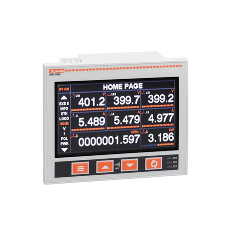
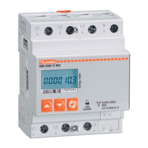
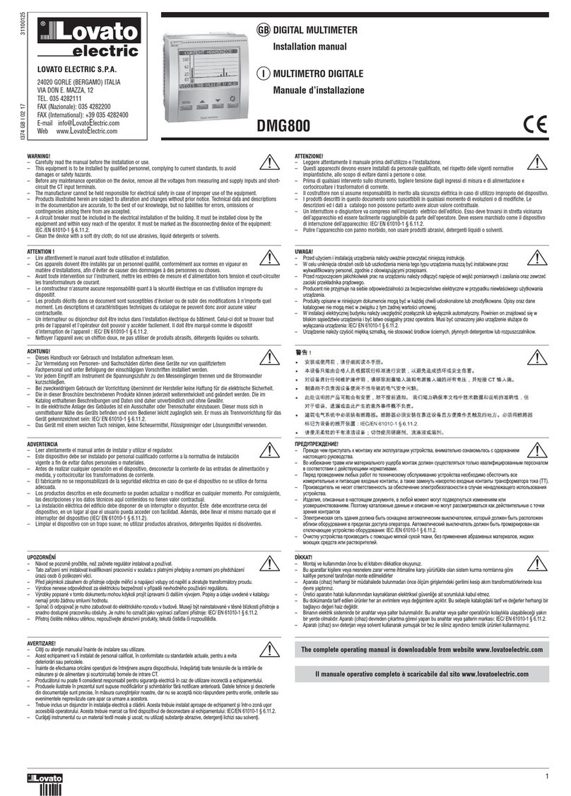
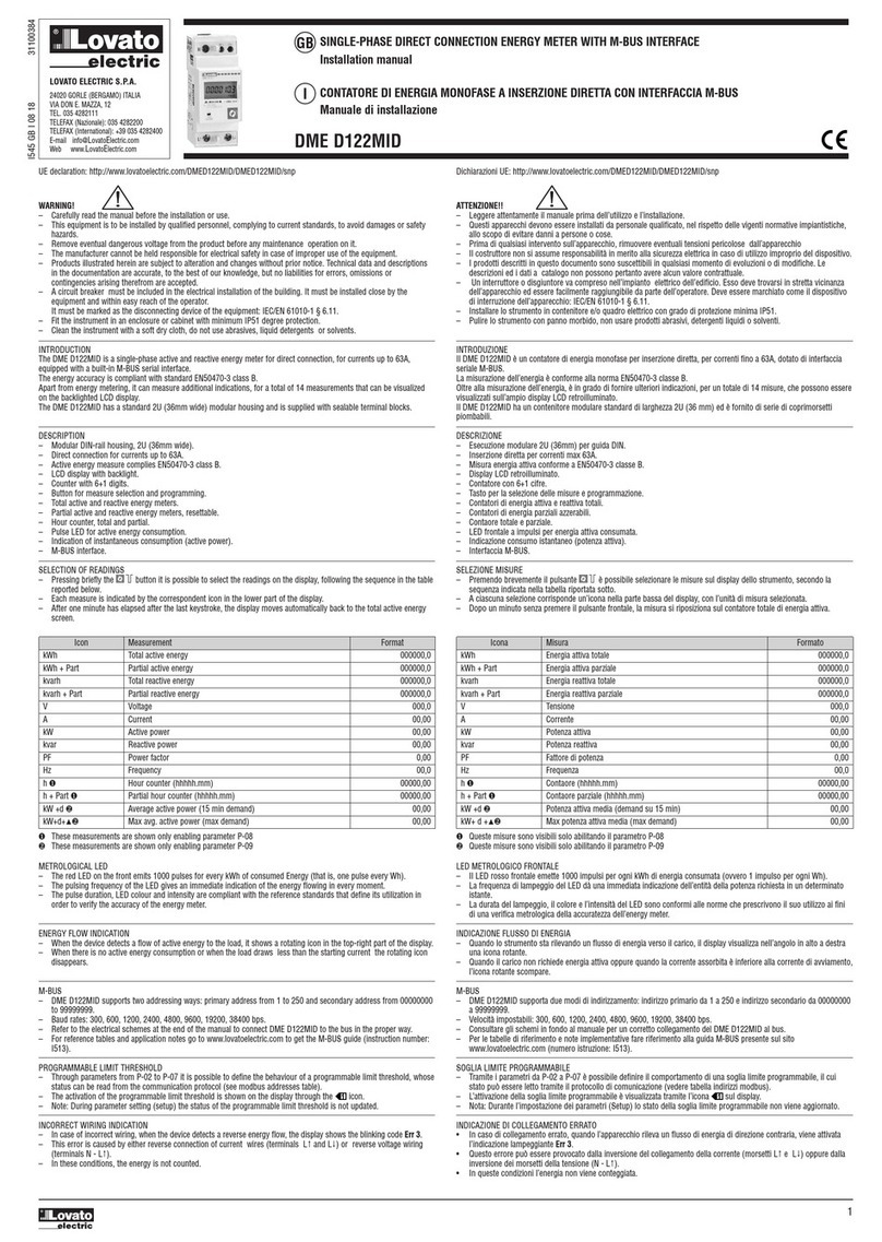
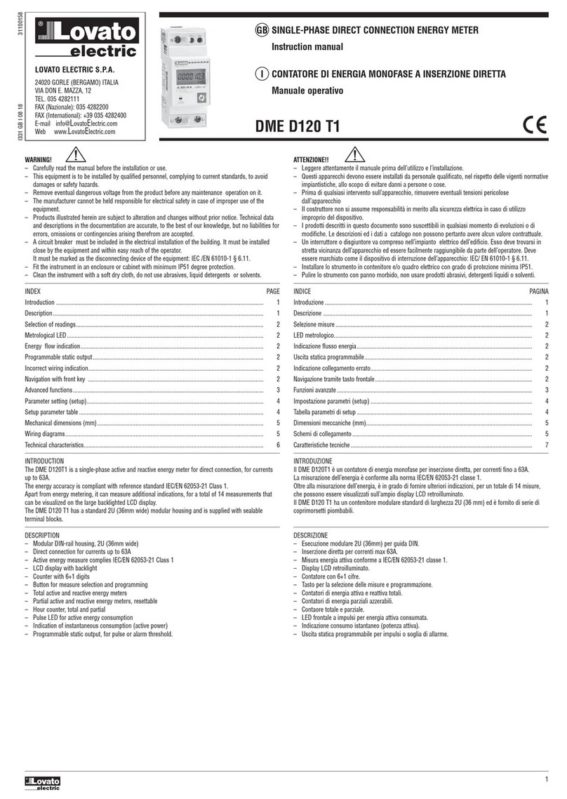
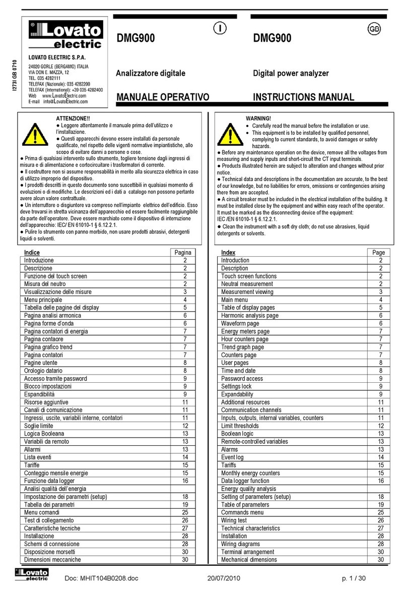
Lovato DML1 User manual

DML1 - DML2 - DML3 - DML4
I75.I.GB.02-00
I
STRUMENTI DI MISURA
DIGITALI
GB
DIGITAL METERING
INSTRUMENTS
GENERALITÀ
I multimetri digitali serie DML consentono la misura delle principali
grandezze elettriche di reti di distribuzione di energia.
La visualizzazione locale delle 40 grandezze misurate viene effettuata
mediante l’utilizzo di quattro display a LED rossi garantendo cosi una
buona leggibilità e una lettura contemporanea di più misure.
L’intuitiva selezione delle grandezze da visualizzare con segnalazione
a LED completa un chiaro e semplice pannello frontale pur fornendo
una grande quantità di informazioni.
Oltre alle grandezze istantanee misurate questi strumenti visualizzano
il picco massimo del valore delle correnti e della potenza attiva ed il
valore della corrente termica.
I multimetri DML sostituiscono così in un unico strumento le funzioni
svolte da voltmetri, amperometri, cosfimetri, wattmetri, varmetri,
frequenzimetri, termometri consentendo un notevole risparmio
economico, una riduzione degli ingombri e del cablaggio ed una
semplificazione nell’acquisto e la gestione degli strumenti essendo un
solo modello adatto a tutte le esigenze di misura locale nei quadri
elettrici, macchine, ecc.
CODICI DI ORDINAZIONE
31 DML1 Versione in esecuzione da incasso 96X96mm con
profondità ridotta.
31 DML2 Versione in contenitore modulare per aggancio rapido
su guida DIN 35mm (EN 50022).
31 DML3 Versione da incasso con misurazione dell’energia
trifase in kWh e kvarh
31 DML4 Versione modulare con misurazione dell’energia
trifase in kWh e kvarh
31 PA96X96 Protezione anteriore (IP54) DML1 - DML3
GRANDEZZE MISURATE
Tensione di fase
e del sistema [V-kV] VL1-N VL2-N VL3-N VL- N
Tensione concatenata [V-kV] VL1-L2 VL2-L3 VL3-L1 VL- L
Corrente di fase e
del sistema [A-kA] IL1 IL2 IL3 I
Fattore di potenza di fase
e del sistema PFL1 PFL2 PFL3 PF
Potenza attiva di fase
e del sistema [W-kW-MW] PL1 PL2 PL3 P
Potenza reattiva di fase e del
sistema [VAr-kVAr-MVAr] QL1 QL2 QL3 Q
Potenza apparente di fase
e del sistema [VA-kVA-MVA] AL1 AL2 AL3 A
Energia attiva trifase [kWh]➊kWh
Energia reattiva trifase kvarh
[kvarh]➊
Frequenza [Hz] FL1
Temperatura [°C] T1
Valori di picco (massimi):
Corrente IL1 MAX -IL2 MAX -IL3 MAX
Potenza PL MAX
Corrente media (termica) IL1MAX (AV)-IL2MAX(AV) -IL3MAX (AV)
➊ Solo per versioni DML3 e DML4
ATTENZIONE!
Questo apparecchio deve essere installato
da personale qualificato, nel rispetto delle vigenti normative
impiantistiche, allo scopo di evitare danni a persone o cose.
I prodotti descritti in questo documento
sono suscettibili in qualsiasi momento di
evoluzioni o di modifiche. Le descrizioni ed i dati a catalogo non
possono pertanto avere nessun valore contrattuale.
INTRODUCTION
The digital multimeters, series DML, allow to monitor all the electrical
parameters present on a distribution line . The local display of 40
electrical readouts is carried out by 4 red LED displays providing at
the same time, easy reading of several of them. A simple front panel
completes the intuitive choice of several electrical parameters, as
wellas a great deal of information. These instruments also display the
maximum peak value of currents, active power and thermal currents.
DML multimeters replace in a sole device, all the functions of
voltmeters, ammeters, power factor meters, wattmeters, varmeters,
frequency meters and temperature sensors, permitting a great saving
of energy, reduced wiring reduction, easier purchase and better
management of instruments considering that the same model
satisfies all the options of local reading on electrical boards,
machinery and so on.
ORDER CODE
31 DML1 Flush mount version DIN 96x96mm with reduced
depth.
31 DML2 Modular version, mounting directly on the 35mm DIN
rail (EN 50022).
31 DML3 Flush mount version including 3-phase energy
readout in kWh or kvarh
31 DML4 Modular version including 3-phase energy readout in
kWh or kvarh
31 PA96X96 Protective cover (IP54) for DML1 - DML3
PARAMETER DISPLAY
Phase and three-phase
voltage [V-kV] VL1-N VL2-N VL3-N VL- N
Voltage between lines [V-kV] VL1-L2 VL2-L3 VL3-L1 VL- L
Phase and three-phase
current [A-kA] IL1 IL2 IL3 I
Phase and three-phase
power factor PFL1 PFL2 PFL3 PF
Phase and three-phase active
power [W-kW-MW] PL1 PL2 PL3 P
Phase and three-phase reactive
power [VAr-kVAr-MVAr] QL1 QL2 QL3 Q
Phase and three-phase
apparent power [VA-kVA-MVA]
AL1 AL2 AL3 A
Three-phase energy (active) kWh
[kWh]➊
Three-phase energy (reactive) kvarh
[kvarh]➊
Frequency [Hz] FL1
Temperature [°C] T1
Maximum peak values:
Current IL1 MAX -IL2 MAX -IL3 MAX
Power PL MAX
Average current (thermal) IL1MAX (AV)-IL2MAX(AV) -IL3MAX (AV)
➊Only for DML3 and DML4 versions
WARNING!
This equipment is to be installed by trained personnel, complying to
current standards, to avoid damages or health and safety hazards.
Products illustrated herein are subject to alterations and changes
without prior notice.
Technical data and descriptions in the catalogue are accurate, to the
best of our knowledge, but no liabilities for errors, omissions or
contingencies arising are accepted.
®
LOVATO S.P.A.
COMPONENTI E SISTEMI
PER AUTOMAZIONE
24020 GORLE
(BERGAMO) ITALIA
VIA DON E. MAZZA, 12
TEL.: 035 4282111
TELEFAX (Nazionale): 035 4282200
TELEFAX (International): +39 035 4282400
Web www.lovatoelectric.com
E-mail [email protected]
1
DML1 - DML3
DML2 - DML4

SICUREZZA
Questo strumento è stato costruito e collaudato in conformità alle
norme IEC 1010 classe 1. Per garantire queste condizioni attenersi
alle istruzioni ed indicazioni contenute nel seguente manuale.
Al ricevimento dello strumento, prima di procedere all’installazione,
controllarne l’integrità e l’eventuale presenza di danni dovuti al
trasporto. Controllare che la tensione di alimentazione e di esercizio
coincidano con i valori prescritti per lo strumento, prima di procedere
alla sua installazione. Non collegare la tensione di alimentazione a
terra. E’ vietata ogni operazione di manutenzione o riparazione
eseguita da personale non autorizzato. Qualora si pervenga, in fase di
esercizio, a considerare una perdita di sicurezza dello strumento,
metterlo fuori servizio ed assicurarsi che non venga utilizzato
inavvertitamente.
L’esercizio non è sicuro quando :
– Lo strumento non funziona più.
– Lo strumento presenta danni chiaramente visibili.
– Dopo gravi danni imputabili al trasporto.
– Dopo uno stoccaggio in condizioni ambientali sfavorevoli.
CONNESSIONI
Per un corretto impiego dello strumento rispettare scrupolosamente
lo schema di cablaggio contenuto nel presente manuale.
Le connessioni sono le stesse per i due modelli e sono suddivise in
tre gruppi:
– Alimentazione ausiliaria:
sono disponibili 4 morsetti per l’alimentazione ausiliaria dello
strumento in modo da poter utilizzare le seguenti tensioni:
0-110 = 100-125V 50-60Hz
0-230 = 220-240V 50-60Hz
0-400 = 380-415V 50-60Hz
è cosi possibile ad esempio prelevare l’alimentazione dalla rete di
misura utilizzando fase e neutro per un sistema a 4 fili, fase e fase in
un sistema a 3 fili senza neutro.
– Ingressi voltmetrici di misura:
sono disponibili 4 morsetti per la connessione alle 3 fasi e neutro
della rete di misura, la tensione massima tra fase e fase non deve
superare 500V rms. Nel caso di applicazione in reti a 3 fili senza
neutro o con neutro non distribuito è sufficiente NON connettere il
morsetto N.
– Ingressi amperometrici di misura:
sono disponibili 6 morsetti per la connessione a 3 TA esterni con
secondario 5A. E’ obbligatorio l’utilizzo dei TA esterni.
NOTE:
E’ fondamentale rispettare la corretta sequenza fasi, non invertire le
connessioni tra le fasi degli ingressi amperometrici e voltmetrici
(es. il TA posto sulla fase L1 deve assolutamente corrispondere
all’ingresso I1 ) e non invertire i morsetti S1 e S2 del TA poiché la
misura dei fattori di potenza e le potenze non sarebbero più
attendibili.
Il sensore di temperatura opportunamente compensato è posto
all’interno degli strumenti nella parte posteriore in modo da misurare
la temperatura all’interno del quadro elettrico in prossimità dello
strumento stesso.
CONNESSIONI DML1 - DML3
CONNESSIONI DML2 - DML4 DML2 - DML4 CONNECTIONS
SAFETY PRECAUTIONS
This instrument is manufactured and tested in compliance with IEC
61010 class 1 standards. In order to warrant these conditions and to
ensure safe operation, the personnel must comply with the
indications and instructions given in this manual.
When the instrument is received and before installing, check that it is
intact and no damage has occurred during transport.
Also, make sure the operating and mains voltages are compatible
with the device characteristics. The instrument power supply must
not be earthed. Maintenance and repair must be carried out by
qualified and authorised personnel only. If there is ever the doubt
that, safety conditions are no longer possible during operation, the
instrument must be removed from service and precautions taken
against accidental use.
Operation is no longer safe when:
– The instrument no longer works.
– There is clearly visible damage.
– After serious damage incurred during transport.
– After long storage in unfavourable conditions.
CONNECTIONS
For a correct instrument use, the given wiring diagram must be
respected.
The connections are the same for both types:
– Auxiliary supply:
Four screw terminals for the instrument auxiliary supply are available
for the following voltages:
0-110 = 100-125V 50-60Hz
0-230 = 220-240V 50-60Hz
0-400 = 380-415V 50-60Hz
The auxiliary supply can possibly be drawn from the monitored
system using the phase and neutral when a 4-wire type or between
lines for a 3-wire one (without neutral).
– Voltage monitoring inputs:
Four screw terminals are available for connections with monitored
3-phase systems with neutral; the maximum voltage between lines
must not be more than 500V rms.
In case of 3-wire systems with neutral (but no relative connection) or
without neutral, it is important to NOT connect terminal N.
– Current monitoring inputs:
Six screw terminals are available for connections with 3 external
current transformers (CT) with 5A secondary. The use of these is
compulsory.
NOTE:
It is fundamental:
– To respect the current phase sequence
– To not invert the connections between the current and voltage
inputs (e.g. CT connected on phase L1 must correspond to input
I1)
– To not invert terminals S1 and S2 of the CT since the power factor
and power readings would no longer be reliable.
The compensated temperature sensor is placed in the rear of the
instrument in such a way as to monitor the temperature of the
electrical board in proximity of the same instrument.
DML1 - DML3 CONNECTIONS
2
PEAK
DML 2
®

SCHEMI DI COLLEGAMENTO WIRING DIAGRAMS
3-PHASE 4-WIRE CONNECTION
DML...
ORGANI DI COMANDO E VISUALIZZAZIONE FRONT PANEL
Legenda :
A: pulsante per la visualizzazione del sistema trifase e dei valori di
picco
B: pulsante per la selezione della grandezza da visualizzare sui
display F
C: pulsante per la selezione della grandezza da visualizzare sul
display G
D: barra LED per l’indicazione della grandezza visualizzata sui
display F
E: barra LED per l’indicazione della grandezza visualizzata sul
display G
F: tre display per la visualizzazione delle grandezze suddivise per
fase. Nel caso sia acceso il LED L rimarrà attivo solo il
display centrale indicando il valore del sistema trifase della
grandezza selezionata. I due LED k e M indicano l’eventuale
fattore di moltiplicazione (lettura k=kilox1.000, lettura
M=megax1.000.000).
G: display per la visualizzazione della grandezza indicata dalla
barra LED E. Il valore delle tensioni si riferisce al sistema
trifase. Il LED k indica la lettura in kilo (x 1.000).
Legend :
A: Push button for the indication of electrical parameters of three
phase system and peak values.
B: Push button for the selection of the electrical variable to
indicate on display F.
C: Push button for the selection of the electrical variable to
indicate on display G.
D: LED bar for the indication of the electrical variable on display F.
E: LED bar for the indication of the electrical variable on display G.
F: Three displays for the indication of electrical readings divided
per phase.
When the L LED is lighted, only the main display will be
active, showing the value of the three phase system of selected
parameter. k and M LED’s show the eventual multiplying factor
that is k=kilo (x1,000) and M=mega (x1,000,000)
G: Display of the electrical readouts indicated by the LED E bar.
The voltage values are referred to the three
phase system. The k
LED denotes that the reading is in kilo (x 1,000).
PEAK
PEAK
DML 2
®
®
DML 1
3
DML1
DML3
DML2
DML4

4
PROGRAMMAZIONE STRUMENTO
Per il corretto funzionamento dei multimetri è necessario
programmare il rapporto di trasformazione dei trasformatori
amperometrici utilizzati.
PROGRAMMAZIONE RAPPORTO DI TRASFORMAZIONE DEI
TRASFORMATORI AMPEROMETRICI ESTERNI.
La programmazione del rapporto TA, inteso come rapporto tra
primario e secondario (esempio con TA 1000/5 si dovrà impostare
200), deve essere effettuata con i pulsanti posti sul fronte:
dopo aver dato alimentazione ausiliaria allo strumento ed atteso
qualche secondo (all’atto dell’accensione tutti i LED e display
lampeggiano alternativamente all’indicazione della versione firmware),
premere contemporaneamente i pulsanti A e C, sul display G apparirà
la scritta SET e sul primo display F la scritta CT , sul display centrale F
il valore del rapporto di trasformazione (impostato su 1 dal
costruttore).
Tenere premuto il pulsante B per incrementare il valore o premere C
per decrementare il valore (la variazione è di una unità per unità).
Per velocizzare l’operazione, tenere premuto costantemente il
pulsante B o C, la variazione avverrà successivamente per decine e
per centinaia. Rilasciando e ripremendo il pulsante si ritornerà a
incrementare o decrementare il valore per unità.
Per confermare la programmazione ripremere il pulsante A (se per 10
secondi non vengono premuti pulsanti lo strumento uscirà
automaticamente dalla programmazione).
NOTE
Quando il rapporto di trasformazione impostato supera 999 il valore
1000 è indicato con l’accensione del LED k; ad esempio per
impostare il valore 1200 si visualizzerà 1.20 sul display centrale F con
l’accensione del LED k.
I valori impostati vengono mantenuti anche in mancanza
dell’alimentazione ausiliaria.
Non sono necessarie altre programmazioni tenendo in considerazione
che lo strumento è completamente autorange (commutazione
automatica della scala di visualizzazione e virgola mobile).
INSTRUMENT SET-UP
For a proper and correct use of the instrument, it is necessary to
program the transformation ratio of the current transformers used
.
TRANSFORMATION RATIO PROGRAMMING FOR THE EXTERNAL
CURRENT TRANSFORMERS
The CT ratio programming, considered as ratio between primary and
secondary (e.g. with a 1000/5 CT, one must program 200), is made
through the front push buttons, as follows:
After a few seconds after the instrument supply (all LED’s and
displays flash at switch on after the version firmware indication),
simultaneously press buttons A and C. The wording SET and CT will
respectively appear on displays G and L1 and the transformation ratio
value on L2 (factory set at 1). By pushing button B, the value
increases while button C, decreases it (the variation is unit by unit).
To speed up this operation, keep button B or C pressed and the
variation takes place by tens and then by hundreds. Unit variation
returns by releasing and pushing the button again.
To confirm programming, press button A again. If no button is
pushed for 10 seconds, the instrument will exit programming.
NOTE
When the programmed transformation ratio exceeds 999, the value of
1000 is indicated by the illuminated k LED. For example, the value of
1200 will be shown as 1.20 on the L2 display and the illuminated k
LED. The programmed values are stored also at the lack of voltage.
No other programming is necessary owing to self-configuration
(automatic switching of the display scale and mobile decimal point).
VISUALIZZAZIONE MISURE
Lo strumento DML è suddiviso in due sezioni distinte:
la prima è composta dai tre display F, dai tasti A e B e dai LED D
la seconda composta dal display G, dal tasto C e dai LED E.
Le due sezioni sono da considerarsi effettivamente come due
strumenti separati in uno, infatti è possibile operare su di una zona
senza modificare la visualizzazione dell’altra (ad esclusione della
visualizzazione dei valori di picco o massimi).
VISUALIZZAZIONE SEZIONE 1
La visualizzazione delle misure viene visualizzata sui display F, dove
vengono rappresentate le tre misure di fase (rispettivamente L1, L2
ed L3) della grandezza indicata dall’accensione di un LED D. Per la
misura delle tensioni concatenate (VL- L) le tre misure si intendono
rispettivamente VL1-L2 VL2-L3 VL3-L1.
Premendo il tasto B si selezionano le varie grandezze visualizzabili
indicate sempre dai LED D.
Premendo il tasto A sul display centrale (L2) verrà visualizzata la
grandezza selezionata in valore trifase (media delle singole fasi per
tensioni, correnti, fattori di potenza, e somma delle singole fasi per le
potenze) con conseguente accensione del LED all’interno del tasto.
Ripremendo lo stesso tasto si ritorna alla visualizzazione delle
grandezze di fase. Notare che l’unità di misura può essere espressa in
kilo o Mega nel caso dell’accensione dei relativi LED.
La visualizzazione del fattore di potenza capacitivo viene
rappresentato con un segno - sul primo digit del display (esempio
lettura -.95 indica un fattore di potenza di 0.95 capacitivo).
VISUALIZZAZIONE SEZIONE 2
Analogamente a quanto avviene nella sezione 1 con il tasto C si
selezionano le grandezze da visualizzare indicate dai LED E (i valori di
tensione si intendono del sistema trifase, la frequenza del canale L1 e
la temperatura dal sensore interno).
MEASUREMENTS DISPLAY
The digital multimeter DML is divided into 2 sections:
–
The first is composed by 3 displays F, buttons A and B and D LED’s.
– One display G, button C and E LED’s compose the second.
The two sections can be considered as separate instruments in one
sole device; in fact, it is possible to work in one section without
displaying anything on the other (excluding the peak value display).
SECTION 1 DISPLAY
The readout display is given on F displays where the three monitored
phases are represented respectively by L1, L2 and L3 of the
parameter indicated by the relative illuminated D LED. For the voltage
between lines measurement (VL-L), the three readings are intended
respectively as VL1-L2, VL2-L3, and VL3-L1.
By pushing button B, the various displayable parameters are selected
and distinguished by the corresponding illuminated D LED.
By pushing button A, the selected parameter, given as three-phase
value (average value for each single phase for voltage, current or
power factor monitoring and total of each single phase for power) is
shown on the middle display (L2) and the LED on the button itself
switches on. Pressing this same button again, the display returns to
phase indication.
The unit of measure can be expressed as kilo (k) or mega (M) in the
case one of corresponding LED’s is switched on. The display of a
capacitive power factor value is given by a minus (-) sign before the
first digit (e.g. the -.95 reading indicates a capacitive power factor
of 0.95).
SECTION 2 DISPLAY
As given above for section 1, by pushing button C, one can display
the parameters indicated by the E LED’s (voltage values are intended
as three-phase systems, the frequency of L1 branch and the
temperature detected by the internal sensor).
PEAK
®
DML 1
PEAK
DML 2
®
DML1 - DML3
DML2 - DML4
VISUALIZZAZIONE CONTATORI DI ENERGIA
Nel caso dei modelli DML3-DML4 la lettura dei contatori di energia
attiva e reattiva selezionata con il tasto C viene visualizzata sui display
F (in questo caso il display G non ha alcuna funzione).
La lettura dei contatori utilizza i 9 digit (massima lettura 99999999.9)
dei display F: la misura viene visualizzata in modo che il display L1
indicherà i primi 3 digit, il display L2 i secondi 3 digit ed il display L3
gli ultimi 3. Ad esempio se: L1=000, L2=028, L3=53.2 la lettura è pari
a 2853.2kWh.
VISUALIZZAZIONE VALORI DI PICCO
Tenendo premuto per almeno 3 secondi il tasto A si attiva la
visualizzazione dei valori massimi o di picco delle correnti e della
potenza attiva trifase. Questa condizione è indicata dal display G che
visualizzerà la scritta PEA (peak) insieme al LED della grandezza
visualizzata. Un ulteriore valore di picco è rappresentato dalla corrente
di picco media (il valore massimo calcolato sul valore medio integrato
ogni 15 minuti) o corrente termica indicata dal display G con scritta
ITH . La selezione della grandezza di picco da visualizzare avviene
premendo il tasto B. Dopo circa 10 secondi dall’ultima pressione sui
tasti lo strumento ritorna automaticamente alla visualizzazione dei
valori istantanei.
CANCELLAZIONE VALORI DI PICCO
Durante la visualizzazione dei valori di picco premendo
contemporaneamente i tasti A e B si effettua la cancellazione dei
valori di picco; durante questa operazione lampeggerà la scritta RES
sui display F. I valori di picco memorizzati vengono mantenuti in
memoria anche alla mancanza dell’alimentazione ausiliaria.
NOTE
Il tempo di acquisizione dei valori di picco istantanei è pari ad 1
secondo.
Ad ogni accensione dello strumento viene sincronizzata l’integrazione
per il calcolo della corrente media su un tempo di 15 minuti. Il tempo
di rinfresco dei display è inferiore al secondo e comunque
corrispondente al tempo di elaborazione delle misure in dipendenza
della metodologia di misura utilizzata consentendo una confortevole
lettura dei valori anche in presenza di repentine variazioni dei
parametri di misura. Nel caso che le misure indicate dallo strumento
non siano attendibili o assurde verificare attentamente la connessione
degli ingressi di misura delle correnti e tensioni poiché devono
assolutamente essere rispettate la sequenza delle fasi, la
corrispondenza delle correnti e delle tensioni della stessa fase
(sull’ingresso L1 andranno connessi la tensione di fase L1 ed il TA
posto sulla fase L1) ed il verso della corrente (connettere i morsetti
S1 e dei TA ai relativi morsetti S1 sullo strumento).
ELECTRIC METER DISPLAY
With the DML3 and DML4 types, the active and reactive energy meter
readouts can be displayed by pushing buttobn C.
Power energy readouts are given on the F displays, with a maximum
9-digit number (i.e. 99999999.9) where as the first 3 digits are given
on the L1 display, the next 3 on L2 and the rest on L3. For example if
L1 shows 000, L2 028 and L3 53.2, the readout value will be
2853.2kWh. At these conditions, display G do not operate.
PEAK VALUE DISPLAY
The display of the maximum or peak current and three-phase active
power values is obtained by keeping button A pushed for at least
3 seconds.
This condition is given on the G display, which will show the wording
PEA (peak) along with the illuminated corresponding LED. Additional
peak values are the average peak current (maximum demand
calculated on the basis of the average value, updated every 15
minutes) and the thermal current, indicated by the ITH wording.
The choice of the peak parameter is made by pressing button B.
If no button is pushed for 10 seconds, the instrument will
automatically display instantaneous readings.
PEAK VALUES CANCEL
During the peak value display, push buttons A and B contemporarily
and peak values will be cancelled. During this operation, the wording
RES, on F displays will flash.
The stored peak values will be maintained even if the auxiliary voltage
is removed.
NOTE
The acquisition time of instantaneous peak values corresponds to 1
second.
At each instrument switch on, the integration time for the average
current calculation is synchronised on an interval of 15 minutes.
The cooling time for the displays is less than 1 second. Moreover,
this corresponds to the monitoring elaboration time, related to the
measure methodology used, and provides a stable view of the values,
also in presence of sudden parameter changes.
In the event the displayed values become unreliable or senseless, it is
essential to carefully check the current/voltage monitoring input
connections. In this case, the phase sequence, the current/voltage
correspondence of the same phase (L1 phase voltage and its relative
CT connected to L1 input) and the direction of current flow
(CT terminals S1 connected to instrument terminals S1) must be
respected.
DIMENSIONI [mm] DIMENSIONS [mm]
Per eventuali problematiche applicative e funzionali non trattate nel
presente manuale contattare il nostro ufficio Servizio Clienti
(Tel. 035 4282422).
Il costruttore declina ogni responsabilità per eventuali danni a cose o
persone derivanti da un uso improprio o non consentito degli
strumenti.
Consult our Customer Service (Tel. +39 035 4282422) for eventual
difficulties for application or function, if any not considered in this
documentation.
The manufacturer declines any responsibility for damage or safety
hazards as result from misuse or improper use of instrument.
5
PEAK
®
DML 1
montaggio su profilato DIN 35mm secondo EN 50022
6 moduli da 17,5 mm.
35mm DIN rail mounting EN 50022
6 module 17.5 mm equivalent.
PEAK
DML 2
®
DML1 - DML3
DML2 - DML4

6
CARATTERISTICHE TECNICHE
MISURE, PRECISIONI
TENSIONE valore efficace delle tensioni di fase e
concatenate, tensione di fase e
concatenata del sistema (media)
range di misura: 20÷500V RMS fase-fase
290V RMS fase-neutro
precisione di misura: ± 0,5% ±1 digit
CORRENTE valore efficace delle correnti di fase e del
valore del sistema (media)
range di misura: 0,02÷5A RMS
precisione di misura: ± 0,5% ±1 digit
visualizzazione: 0,02÷9999Adigit
FREQUENZA frequenza della fase L1
range di misura: 40÷500Hz
precisione di misura: ± 0,5% ±1 digit
POTENZE potenza attiva, reattiva, apparente di fase
e del sistema (somma)
range di misura: 0,001÷9990kW
0,001÷9990kvar
0,001÷9990kVA
precisione di misura: ± 1% ±1 digit
FATTORE fattore di potenza di fase e del sistema
DI POTENZA (media)
range di misura: - 0,1÷0,1
precisione di misura: ± 1% ±1 digit
TEMPERATURA temperatura misurata con sensore interno
compensato
range di misura: 0÷60°C
precisione di misura: ± 2°C
tempo assestamento misura
all’accensione 15 minuti
ALIMENTAZIONE AUSILIARIA, INGRESSI
ALIMENTAZ.
100÷125 / 220÷240 / 380÷415V ±10%
AUSILIARIA frequenza: 50-60Hz
assorbimento: 3VA
INGRESSI 20÷500V fase-fase;
TENSIONE sovraccarico permanente: + 20%
impedenza ingresso: 1M
inserzione su linee monofase, trifase a tre
fili, trifase a 4 fili.
INGRESSI 0,02÷5A
CORRENTE sovraccarico permanente: + 20% da TA
esterno con secondario 5A
primario programmabile: 5÷10000A
autoconsumo: <0,5VA
GENERALI
DISPLAY, 4 display a LED rossi (10mm) ognuno
OPERATORI composto da 3 digit da 8 segmenti,
3 pulsanti per selezione misure e
programmazione rapporto trasformazione
TA esterni
MECCANICHE gradi di prot.: IP52 frontale
IP20 contenitore e morsettiere
Peso:
DML1: 0.620kg.
DML2: 0.470kg.
DML3: 0.620kg.
DML4: 0.470kg.
Connessione con morsettiere a vite per
cavo 2,5/4mm2
Contenitore plastico autoestinguente
DML1 - DML3: esecuzione da incasso
DIN 96X96x95mm
DML2 - DML4: esecuzione montaggio
DIN 35mm, dimensioni 6 moduli da
17,5mm
AMBIENTALI temperatura di funzionamento:
-10÷60°C
temperatura immagazzinaggio:
-25÷80°C
Umidità: <90%
NORME DI EN 50082-1; EN 50081-2; EN 61010-1
RIFERIMENTO
TECHNICAL CHARACTERISTICS
READINGS AND ACCURACY
VOLTAGE Effective value of phase and line voltages,
phase and three phase system voltage
(average)
Range: 20-500V RMS phase to phase
290V RMS phase to neutral
Accuracy: ± 0.5% ±1 digit
CURRENT Effective value of phase current and
system value (average)
Range: 0.02-5A RMS
Accuracy : ± 0.5% ±1 digit
Display : 0.02-9999A digit
FREQUENCY L1 phase frequency
Range: 40-500Hz
Accuracy: ± 0.5% ±1 digit
POWER Phase and system (total) active-reactive-
apparent power values.
Range: 0.001-9990kW
0.001-9990kvar
0.001-9990kVA
Accuracy : ± 1% ±1 digit
POWER Phase and three phase system (average)
FACTOR power factor
Range: - 0.1 to +0.1
Accuracy: ± 1% ±1 digit
TEMPERATURE Measured by internal compensated
sensor.
Range: 0 to +60°C
Accuracy: ± 2°C
Steady readout time at power on: 15min
AUXILIARY VOLTAGE AND CURRENT INPUT
AUXILIARY
100-125 / 220-240 / 380-415V ±10%
SUPPLY Frequency: 50-60Hz
Power consumption: 3VA
VOLTAGE 20 to 500V phase-phase;
INPUTS Permanent overload: + 20%
Input impedance: 1M
Connection to single phase line, three
phase line with 3 wires, three phase line
with 4 wires.
CURRENT 0,02 to 5A
INPUTS Permanent overload: + 20% from external
CT with 5A secondary.
Programmable primary: 5 to 10000A
Consumption: <0.5VA
GENERAL SPECIFICATIONS
DISPLAY 4 red LED displays (10 mm) each
composed by 3 digits of 8 segments,
3 buttons to select readout and ratio
programming of external current
transformer
MECHANICAL Protection: IP52 on front
IP20 housing and terminals
Weight:
DML1: 0.620kg.
DML2: 0.470kg.
DML3: 0.620kg.
DML4: 0.470kg.
Connection with screw terminal block for
2.5/4mm2cable section.
Self extinguishing plastic housing
DML1 - DML3: Flush mounting DIN47000
96x96x95mm
DML2 - DML4: 35mm DIN rail mounting
EN 50022, 6 module 17.5mm equivalent
AMBIENT Operating temperature: -10 to +60°C
Storage temperature: -25 to +80°C
Relative humidity: <90%
REFERENCE EN 50082-1; EN 50081-2; EN 61010-1
STANDARDS
This manual suits for next models
3
Table of contents
Other Lovato Measuring Instrument manuals

Lovato
Lovato DME D332 User manual

Lovato
Lovato DME D330 User manual

Lovato
Lovato DME D120 T1 User manual

Lovato
Lovato DME D122 User manual

Lovato
Lovato DME D305T2MID User manual

Lovato
Lovato DMG900 User manual

Lovato
Lovato DMG110 User manual

Lovato
Lovato DME D305T2 User manual

Lovato
Lovato DMED301MID User manual

Lovato
Lovato DMG900 User manual
Popular Measuring Instrument manuals by other brands

PVE
PVE PVPM 1500X user manual

Lighthouse Worldwide Solutions
Lighthouse Worldwide Solutions ApexZ Operator's manual

Fluke
Fluke 871A Preliminary operating instructions

Hanna Instruments
Hanna Instruments HI 93726 instruction manual

GPI
GPI 09 COMPUTER ELECTRONICS owner's manual

Kusam-meco
Kusam-meco KM 175D Operation manual