4
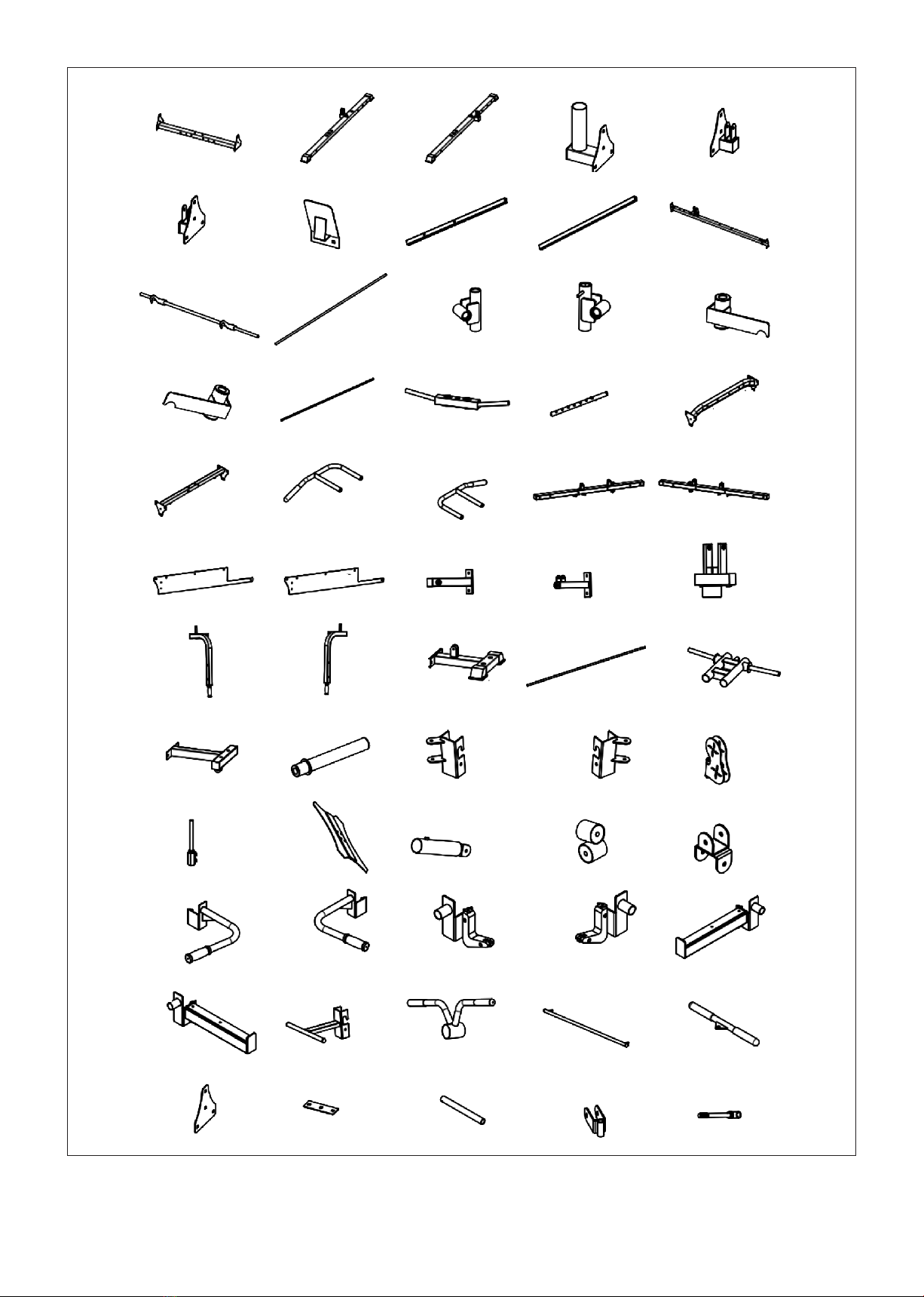
II. PARTS LIST
| PARTS LIST
Key No. Description Qty.
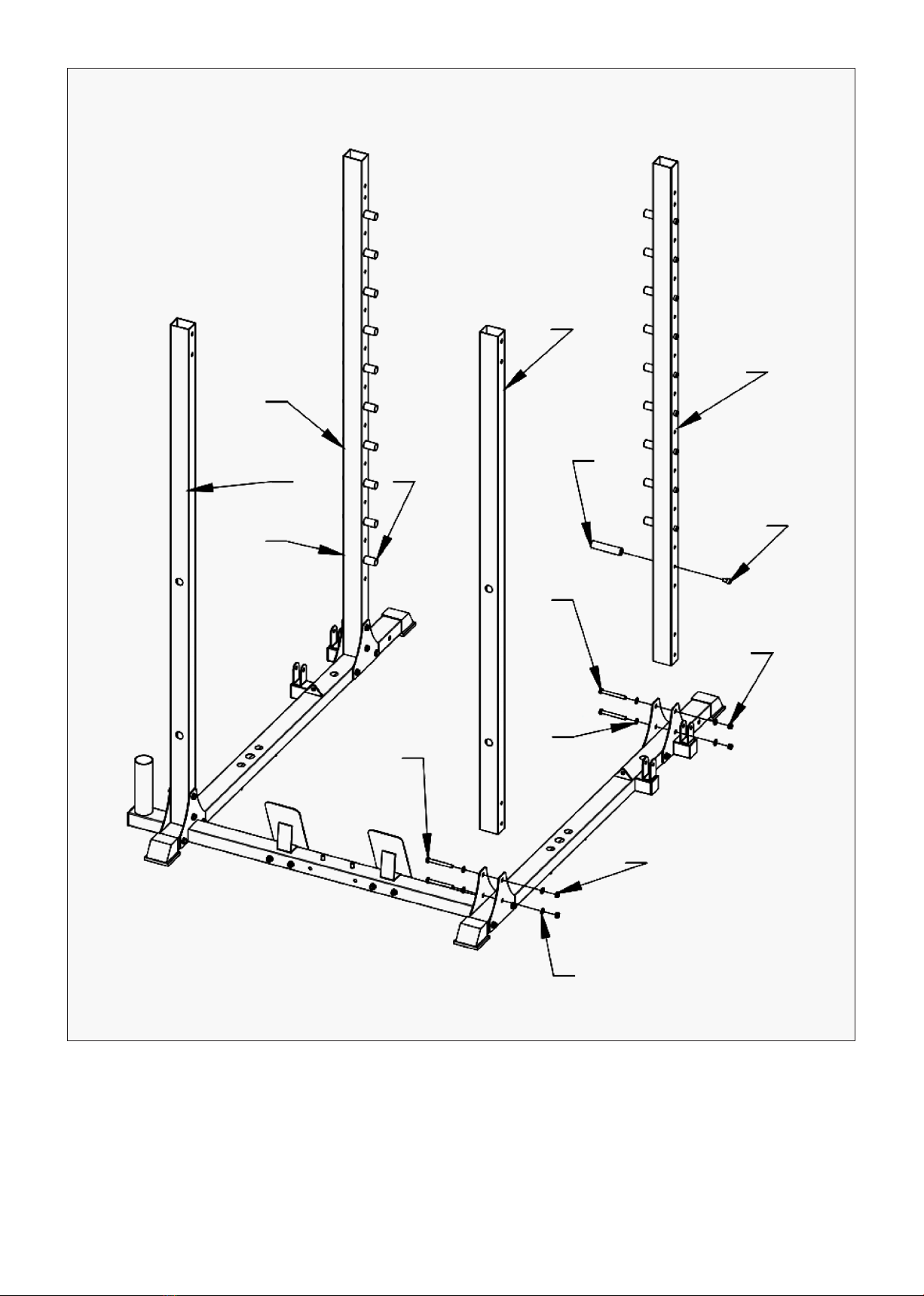
1Bottom Connecting Frame
Welding Frame 1
2Right Floor Frame 1
3Left Floor Frame 1
4Barbell Holder 1
5Right Connecting Sheet Welding 2
6The Left Connection Sheet is
Welded Together 2
7Foot Plate 2
8Back Column Tube 2
9Front Column Tube 2
10 Backrest Master Frame 1
11 Grip Rod Welding 1
12 Smith Bar Rail 2
13 Welded Sliding Sleeve Left 1
14 Welded Sliding Sleeve Right 1
15 Smith Safety Bar Left 1
16 Smith Safety Bar Right 1
17 Stainless Steel Guide Rod 4
18 Horizontal Pipe Welding of the
Bell Plate 2
19 Selection Lever 2
20 Front Upper Beam Pipe Welding 1
21 The Rear Upper Connecting
Frame 1
22 Chin Up Arm Right 1
23 Chin Up Arm Left 1
24 Upper Left Side Connecting
Frame 1
25 Upper Right Side connecting
Frame 1
26 Upper Right Decorative Board 1
27 Upper Left Decorative Board 1
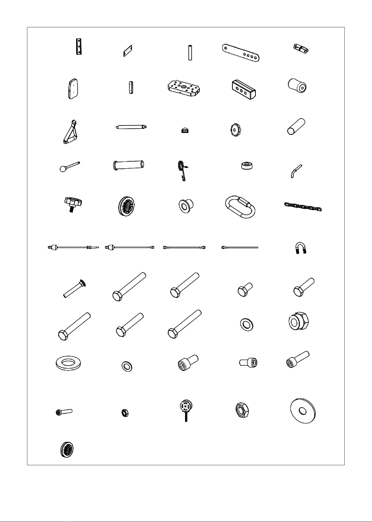
Key No. Description Qty.
28 Top Joint Frame 1
29 Connect the Support Frame 1
30 Front Press Base 1
31 Right Butterfly Arm 1
32 Left Butterfly Arm 1
33 Rear Weight Base Frame 1
34 Guide Rod 2
35 Counter-balanced Carriage 1
36 Weight Stack Upper Frame 1
37 Barbell Sleeve 2
38 Left Adjustment U Base Welding 1
39 Right Adjust U Base Welding 1
40 Bird Pulley Box Welding Joint 2
41 The Rope Buckle Silk 2
42 Pattern Plate Welding 1
43 Landmine Post 1
44 Landmine Connecting Shaft 1
45 Double U Seat Welding 1
46 Dip Handle Left 1
47 Dip Handle Right 1
48 J-Hook 1
49 J-Hook 1
50 Long Safety Bar Left 1
51 Long Safety Bar Right 1
52 Leg Movement Frame 1
53 Landmine Post Handle 1
54 Long Pull Rod Welding 1
55 Straight Bar Attachment 1
56 Fixed Plate 3
57 110 Flat Connecting Sheets 2